pull to seat connector assembly process
- 格式:pdf
- 大小:159.39 KB
- 文档页数:7
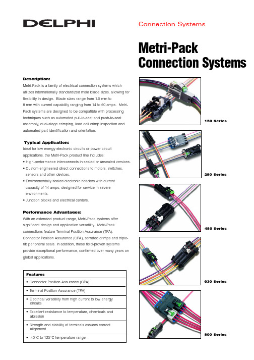
Metri-PackConnection SystemsConnection SystemsDescription:Metri-Pack is a family of electrical connection systems which utilizes internationally standardized male blade sizes, allowing for flexibility in design. Blade sizes range from 1.5 mm to8 mm with current capability ranging from 14 to 60 amps. Metri-Pack systems are designed to be compatible with processing techniques such as automated pull-to-seat and push-to-seat assembly, dual-stage crimping, load cell crimp inspection and automated part identification and orientation.Typical Application:Ideal for low energy electronic circuits or power circuit applications, the Metri-Pack product line includes:• High-performance interconnects in sealed or unsealed versions. • Custom-engineered direct connections to motors, switches,sensors and other devices.• Environmentally sealed electronic headers with current capacity of 14 amps, designed for service in severe environments.• Junction blocks and electrical centers.Performance Advantages:With an extended product range, Metri-Pack systems offer significant design and application versatility. Metri-Pack connections feature Terminal Position Assurance (TPA),Connector Position Assurance (CPA), serrated crimps and triple-rib peripheral seals. In addition, these field-proven systems provide exceptional performance, confirmed over many years on global applications.150 Series280 Series480 Series630 Series800 SeriesFeatures•Connector Position Assurance (CPA) •Terminal Position Assurance (TPA)•Electrical versatility from high current to low energy circuits •Excellent resistance to temperature, chemicals and abrasion •Strength and stability of terminals assures correct alignment •-40°C to 125°C temperature rangeMetri-Pack Connection SystemsPrinted on Recycled Paper.©2000, Delphi Automotive Systems. All rights reserved.Printed in the U.S.A.DP-01-E-023 0401/xM-xxP .O. Box 431, Warren, OH 44486 USA Tel: [1] 330.759.6000Fax: [1] 330.759.6085Connection SystemsApplication Guidelines150 SeriesCable Range (mm 2) . . . . . . . . . . . . . . . . . . 0.35 – 1.0Current Range (amps) . . . . . . . . . . . . . . . . 0 – 14Temperature Range (°C) . . . . . . . . . . . . . . . -40 to 125Resistance . . . . . . . . . . . . . . . . . . . . . . . . . <10m Ω@ 20mV Voltage Drop . . . . . . . . . . . . . . . . . . . . . . . <10.0mV/amp Centerline Spacing – unsealed (mm). . . . . . 3.5Centerline Spacing – sealed (mm). . . . . . . . 6.0Blade Width (mm) . . . . . . . . . . . . . . . . . . . . 1.5280 SeriesCable Range (mm 2) . . . . . . . . . . . . . . . . . . 0.35 – 5.0Current Range (amps) . . . . . . . . . . . . . . . . 0 – 30Temperature Range (°C) . . . . . . . . . . . . . . . -40 to 125Resistance. . . . . . . . . . . . . . . . . . . . . . . . . . <10m Ω@ 20mV Voltage Drop . . . . . . . . . . . . . . . . . . . . . . . <3.0mV/amp Centerline Spacing – unsealed (mm). . . . . . 5.0Centerline Spacing – sealed (mm). . . . . . . . 7.7Blade Width (mm) . . . . . . . . . . . . . . . . . . . . 2.8480 SeriesCable Range – unsealed (mm 2) . . . . . . . . . 0.35 – 5.0Cable Range – sealed (mm 2) . . . . . . . . . . . 0.50 – 5.0Current Range (amps) . . . . . . . . . . . . . . . . 0 – 42Temperature Range (°C) . . . . . . . . . . . . . . . -40 to 125Resistance . . . . . . . . . . . . . . . . . . . . . . . . <10m Ω@ 20mV Voltage Drop . . . . . . . . . . . . . . . . . . . . . . . <3.0mV/amp Centerline Spacing – unsealed (mm). . . . . . 6.9Centerline Spacing – sealed (mm). . . . . . . . 9.5Blade Width (mm) . . . . . . . . . . . . . . . . . . . . 4.8630 SeriesCable Range – unsealed (mm 2) . . . . . . . . . 0.35 – 5.0Cable Range – sealed (mm 2) . . . . . . . . . . . 0.50 – 5.0Current Range (amps) . . . . . . . . . . . . . . . . 0 – 46Temperature Range (°C) . . . . . . . . . . . . . . . -40 to 125Resistance . . . . . . . . . . . . . . . . . . . . . . . . <10m Ω@ 20mV Voltage Drop . . . . . . . . . . . . . . . . . . . . . . . <3.0mV/amp Centerline Spacing – unsealed (mm). . . . . . 8.5Centerline Spacing – sealed (mm). . . . . . . . 10.8Blade Width (mm) . . . . . . . . . . . . . . . . . . . . 6.3800 SeriesCable Range (mm 2) . . . . . . . . . . . . . . . . . . 2.0 – 8.0Current Range (amps) . . . . . . . . . . . . . . . . 0 – 60Temperature Range (°C) . . . . . . . . . . . . . . . -40 to 125Resistance . . . . . . . . . . . . . . . . . . . . . . . . <10m Ω@ 20mV Voltage Drop . . . . . . . . . . . . . . . . . . . . . . . <3.0mV/amp Centerline Spacing – unsealed (mm). . . . . . 10.3Blade Width (mm) . . . . . . . . . . . . . . . . . . . . 8.0。


OFS EZ Installation Procedures for 640-252-044-01 Instruction Sheet ST® II Connector Comcode: 846 900 678on Buffered and SBJ Fibers,and Jacketed Single-Fiber CableFor P2020C-C-125 and P2020F-Z-125 Connectors With 0.9 mm Buffered or Strength Buffered Jacket (SBJ) FibersNOTE:Recommended Usage Temperatures for Adhesive:Storage: -5 C to 30 C (23 F to 86 F)Installation: 0 C to 38 C (32 F to 100 F)Operating: -40 C to 75 C (-40 F to 167 F)1.Shake the bottle of adhesive and primer vigorously. Remove the cap from the bottle ofadhesive. If the adhesive has not been opened, poke a hole in the tip of the nozzle witha straight pin. Remove the plunger and cap from a syringe and load the adhesive into thesyringe. Replace the plunger and twist a syringe tip into place. As a second option,simply twist a syringe tip onto the nozzle of the adhesive bottle making sure that it fitssnugly. Also, place a syringe tip onto a 3 cc syringe and twist to lock it in place. Removethe top from the bottle of primer and draw 0.5 cc of primer into the syringe (Note: Oncethe installation procedure has been completed, any extra primer in the syringe may bereturned to the original bottle; however, the syringe tip should be removed to avoidgetting adhesive which may be on the tip mixed in with the primer).2.Slip the buffer cap (cap extender) and the buffer support onto the buffered fiber to beterminated.3.Prepare the buffered fiber as shown below using the appropriate tools. The outer jacketmay be removed with the 700A Stripping Tool. Clean the stripped fiber with a wipedampened with isopropyl alcohol to remove any residual coating.Issue 5 February 2002 © 2002 Fitel USA Corp Page 1 of 10All Rights ReservedPrinted in U.S.A.640-252-044-01Instruction Sheeting the syringe with the primer in it, apply primer to 0.25 inches of the buffer. Avoidgetting the primer on the fiber. If several connectors are being terminated, it isrecommended that all of the buffers be primed before moving on to the next step.5.Make sure that the hole in the connector tip is clear of any foreign matter. Use musicwire to clear the hole if necessary. Place a wipe on the work table. Using the syringe,place a drop of primer on the wipe. Wipe the end of the connector through the primer onthe wipe one time.6.Gently insert the syringe tip on the adhesive into the back of the connector until it bottomsand inject the adhesive into the connector until a bead of adhesive forms on the tip of theferrule. The adhesive bead should cover at least 1/2 of the ferrule end face. Withdrawthe syringe tip from the connector but maintain pressure on the bottle or syringe to fill theback end of the connector with the adhesive.7.IMMEDIATELY insert the fiber through the connector, carefully feeling for the ferrulecapillary. Rotate the connector as the fiber is inserted to allow the fiber to pass throughthe connector without hanging up. Once the fiber has been fully inserted, use the syringeto place a drop of primer over the bead of adhesive on the ferrule end face. Be carefulnot to break the fiber. Seat the fiber into the connector making sure the buffer iscompletely seated against the ceramic inside the connector. Slip the buffer support ontothe connector barrel and rotate the support to allow for proper adhesive distribution.Apply a drop of Loctite Super Bonder to the threads of the buffer cap (cap extender). Slipthe cap extender over the buffer support and screw the extender into the connector body.Again, make sure that the fiber is fully seated into the connector and place a micro clip(1043A Tool) on the buffer support to make sure the fiber is not inadvertently pulled out ofthe connector. Place the installed connector in a 600A or 600B Connector Holder toprotect the exposed fiber. Place the assembly in the 971A-1 Holder Block. Allow theadhesive to cure at least one (1) minute.Page 2 of 10 Issue 5 February 2002640-252-044-018.Remove the 600A or 600B Connector Holder(s). Carefully wipe any uncured adhesivefrom around the fiber where it protrudes from the adhesive bead using the edge of awipe. Be careful not to break the exposed fiber. Using a light sawing motion with acleaving tool (the 975A Cleaving Tool may be used), score the fiber at the crest of theadhesive bead. Using a gentle straight pull, remove the exposed fiber. DO NOT BENDAND BREAK THE FIBER, A STRAIGHT PULL WILL YIELD A BETTER CLEAVE!With the connector ferrule pointing upward, polish the cleaved fiber down flush with theadhesive bead by running the brown side of a sheet of Type A Paper over the fiber usinglight circular or figure-8 strokes. This will reduce the risk of breaking the fiber during thenext polishing step.9.Clean the polishing plate and the 400A, 400B, or 1510A Polishing Tool with a wipemoistened with isopropyl alcohol. Blow the plate and polishing tool dry with compressedair.10.Place a sheet of Type A (brown foam-backed) Polishing Paper onto the glass plate, foamside down. Starting with extremely light pressure, polish the connector on the Type APaper using figure-8 strokes. (Note:EXTREMELY light pressure should be used duringthe first few polishing strokes to avoid breaking the fiber.) Polish the connector until ashiny halo can be observed around a thin layer of adhesive remaining on the tip. Startwith a fresh area of the polishing paper for each connector to be polished.11.Place the Type C (gray mylar-backed) Polishing Paper onto the glass plate (glossy sidedown). One wipe can be used under the Type C polishing paper for the first few figure-8s, to protect the fiber. Using figure-8 strokes, polish the connector until all of theremaining adhesive is removed. Start with a fresh area of the paper for each connectorbeing polished.12.Remove the connector from the polishing tool and clean both the connector and tool witha wipe dampened with isopropyl alcohol. Then use canned air to dry the connector tip.Remove the 1043A Micro Clip if used.13.Inspect the fiber end using the 300B Microscope. (CAUTION: Do not use a laser orLED to illuminate the core area for viewing.) An acceptable fiber end is free of cracks,chips, or scratches in the core area. If the fiber is unacceptable, the fiber must bereterminated.14.If the fiber end is acceptable and the connector is not to be used immediately, cover theend with the protective cap.Issue 5 February 2002 Page 3 of 10640-252-044-01Instruction SheetFor P2020C-C-125 and P2020F-Z-125 Connectors With Jacketed Single-Fiber CablesNOTE:Recommended Usage Temperatures for Adhesive:Storage: -5 C to 30 C (23 F to 86 F)Installation: 0 C to 38 C (32 F to 100 F)Operating: -40 C to 75 C (-40 F to 167 F)1.Shake the bottle of adhesive and primer vigorously. Remove the cap from the bottle ofadhesive. If the adhesive has not been opened, poke a hole in the tip of the nozzle witha straight pin. Remove the plunger and cap from a syringe and load the adhesive into thesyringe. Replace the plunger and twist a syringe tip into place. As a second option,simply twist a syringe tip onto the nozzle of the adhesive bottle making sure that it fitssnugly. Also, place a syringe tip onto a 3 cc syringe and twist to lock it in place. Removethe top from the bottle of primer and draw 0.5 cc of primer into the syringe (Note: Oncethe installation procedure has been completed, any extra primer in the syringe may bereturned to the original bottle; however, the syringe tip should be removed to avoidgetting adhesive which may be on the tip mixed in with the primer).2.Slip the cable support and the appropriate crimp sleeve onto the cable.3.Prepare the single-fiber cable as shown using the appropriate tools. The outer jacketmay be removed with the 700A Stripping Tool. If 1800 or 2000 Series Cordage is beingterminated, the MS1-08N-5B5-FS40 Stripping Tool may be used to remove the buffer. If9000 Series Cordage is being terminated, the 1026A Heat-Strip Tool (CC# 105514764) isrecommended. Clean the stripped fiber with a wipe dampened with isopropyl alcohol toremove any residual coating.Page 4 of 10 Issue 5 February 2002640-252-044-01ing the syringe with the primer in it, apply primer to 0.25 inches of the buffer. Avoidgetting the primer on the fiber and the strengthening yarn. If several connectors arebeing terminated, it is recommended that all of the buffers be primed before moving on tothe next step.5.Make sure that the hole in the connector tip is clear of any foreighn matter. Use musicwire to clear the hole if necessary. Place a wipe on the work table. Using the syringe,place a drop of primer on the wipe. Wipe the end of the connector through the primer onthe wipe one time.6.Gently insert the syringe tip on the adhesive into the back of the connector until it bottomsand inject the adhesive into the connector until a bead of adhesive forms on the tip of theferrule. The adhesive bead should cover at least 1/2 of the ferrule end face. Withdrawthe syringe tip from the connector but maintain pressure on the bottle or syringe to fill theback end of the connector with the adhesive.7.IMMEDIATELY insert the fiber through the connector, carefully feeling for the ferrulecapillary. Rotate the connector as the fiber is inserted to allow the fiber to pass throughthe connector without hanging up. Once the fiber has been fully inserted, use the syringeto place a drop of primer over the bead of adhesive on the ferrule end face. Be carefulnot to break the fiber.8.Slip the crimp sleeve over the outer jacket of the cable and strengthening yarn and ontothe connector barrel. Place the installed connector in a 600A or 600B Connector Holderto protect the fiber. Position the 600A or 600B Connector Holder pins onto the connectorbody as shown in Detail A.Issue 5 February 2002 Page 5 of 10640-252-044-01Instruction Sheet9.This will allow the sleeve to be fully exposed for crimping. Before crimping, make surethe sleeve is butted against the connector. Place position B (for 2.4 mm cable) of the102A Crimping Tool over the sleeve so that the first two indentations on the sleeve willappear over the connector barrel and the third appears over the cable jacket. This willinsure a good crimp and prevent cable rotation. Squeeze the crimping tool handles untilthey release. Rotate the connector 90 degrees and crimp again. (Note: Use position Con the crimping tool for 3 mm cable). Place a drop of Loctite Super Bonder on thethreads of the cable support. Slip the support over the crimped sleeve and screw thesupport into the connector body. Place the assembly in the 971A-1 Holder Block. Allowthe adhesive to cure for at least one (1) minute.10.Remove the 600A or 600B Connector Holder(s). Carefully wipe any uncured adhesivefrom around the fiber where it protrudes from the adhesive bead using the edge of awipe. Be careful not to break the exposed fiber. Using a light sawing motion with acleaving tool (the 975A Cleaving Tool may be used), score the fiber at the crest of theadhesive bead. Using a gentle straight pull, remove the exposed fiber. DO NOT BENDAND BREAK THE FIBER, A STRAIGHT PULL WILL YIELD A BETTER CLEAVE!With the connector ferrule pointing upward, polish the cleaved fiber down flush with theadhesive bead by running the brown side of a sheet of Type A Paper over the fiber usinglight circular or figure-8 strokes. This will reduce the risk of breaking the fiber during thenext polishing step.11.Clean the polishing plate and the 400A, 400B, or 1510A Polishing Tool with a wipemoistened with isopropyl alcohol. Blow the plate and polishing tool dry with compressedair.12.Place a sheet of Type A (brown foam-backed) Polishing Paper onto the glass plate, foamside down. Starting with extremely light pressure, polish the connector on the Type APaper using figure-8 strokes. (Note: EXTREMELY light pressure should be used duringthe first few polishing strokes to avoid breaking the fiber.) Polish the connector until ashiny halo can be observed around a thin layer of adhesive remaining on the tip. Startwith a fresh area of the polishing paper for each connector to be polished.Page 6 of 10 Issue 5 February 2002640-252-044-0113.Place the Type C (gray mylar-backed) Polishing Paper onto the glass plate (glossy sidedown). One wipe can be used under the Type C polishing paper for the first few figure-8s,to protect the fiber. Using figure-8 strokes, polish the connector until all of the remainingadhesive is removed. Start with a fresh area of the paper for each connector beingpolished.14.Remove the connector from the polishing tool and clean both the connector and tool witha wipe dampened with isopropyl alcohol. Then use canned air to dry the connector tip.Remove the 1043A Micro Clip if used.15.Inspect the fiber end using the 300B Microscope. (Caution: Do not use a laser or LEDto illuminate the core area for viewing.) An acceptable fiber end is free of cracks, chips,or scratches in the core area. If the fiber is unacceptable, the fiber must be reterminated.Issue 5 February 2002 Page 7 of 10640-252-044-01Instruction SheetPage 8 of 10 Issue 5 February 2002Ordering Information 1032F ToolKit (Comcode 106736929)Kit Quantity DescriptionReplacement CC# Replacement Quantity 1102A Crimping Tool 104389903 1 Tool 1300B Microscope 104412077 1 Microscope 1400B Polishing Tool 105246185 1 Tool 12600A Connector Holders 104153937 12 Holders 1 700A Stripping Tool 104278478 1 Tool 1 MS1-08N-5B5-FS40 Strip Tool 105257414 1 Tool2971-A-1 Holder Blocks 104229398 1 Holder 1 975A Cleaving Tool 103808770 1 Tool1 Scissors105257364 2 Scissors 16-inch Scale 105257356 5 Scales 1Alcohol Bottle 105257463 2 Bottles 1Glass Plate 105075618 2 Plates 11 Stripping Tool (R4366) 105114581 1 Tool 1Instruction Manual 105536718 1 Manual 15Micro Clips (1043A) 106228455 15 Micro Clips 1 1039A Template (1039A) 1060751465 Templates 1 Eye LoupeN.A.640-252-044-01 D-182668 Kit (Comcode 106731367)The D-182668 Kit of Consumables contains consumables to install 50 multimode ST Connectors. The kitincludes fifty (50) P2020C-C-125 Connectors.Kit Quantity Description Replacement CC# Replacement Quantity2 Pkgs. Wipes 105205678 250 Sheets1 Vial Music Wire 105071013 4 Vials15 Syringes Syringes 105257422 10 Syringes25 Tips Dispensing Tips 105157879 125 Tips1 Bottle Adhesive 106730856 1 Bottle1 Bottle Primer 106730849 1 Bottle25 Sheets Type A Polishing Paper 105488175 100 Sheets25 Sheets Type C Polishing Paper 105076798 100 Sheets1 Copy Instruction Sheet 106746647 1 Copy1 Copy Instruction Sheet (ST II+) 107107799 1 Copy50 P2020C-C-125 Connectors 105143911 1 ConnectorIssue 5 February 2002 Page 9 of 10640-252-044-01Instruction SheetD-182709 Kit (Comcode 106736937)The D-182709 Kit of Consumables contains consumables to install 500 multimode ST Connectors. TheP2020C-C-125 Connectors are not included in this kit.Kit Quantity Description Replacement CC# Replacement Quantity10 Pkgs. Wipes 105205678 250 Sheets5 Vial Music Wire 105071013 4 Vials75 Syringes Syringes 105257422 10 Syringes125 Tips Dispensing Tips 105157879 125 Tips2 Bottles Adhesive 106730856 1 Bottle2 Bottles Primer 106730849 1 Bottle125 Sheets Type A Polishing Paper 105488175 100 Sheets125 Sheets Type C Polishing Paper 105076798 100 Sheets2 Copies Instruction Sheet 106746647 1 CopyPage 10 of 10 Issue 5 February 2002。

WARNINGWARNING: DO NOT use this product without first completely reading and understanding these instructions and any additional instructional material supplied with this product. If you are unable to understand the warnings, cautions or instructions, contact a healthcare professional, dealer or technical personnel before attempting to use this equipment - otherwise, injury or damage may occur.WARNING: DO NOT use the rollator if there is any damage to the frame.WARNING: DO NOT use the rollator as a wheelchair or transport device. Rollators are not intended to be propelled while seated.WARNING: If components are damaged or missing, contact your distributor immediately. DO NOT substitute parts.WARNING: Before use, ensure that all assembled parts are secure and all hardware is tightened.WARNING: Care should be taken to ensure that all hand and height adjustments are secure, and that wheels and moving objects are in good working order before using this rollator.WARNING: When using the rollator in a stationary position, the hand brakes MUST be locked.WARNING: ALWAYS observe the user weight limitation.WARNING: Notice for California Customers-California Proposition 65 WARNING: This product contains a chemical known to the State of California to cause cancer and reproductive or developmental harm.WARNING: DO NOT attempt to reach objects if you have to move forward in the seat. Reaching for these objects will cause a change to the weight distribution of the rollator and may cause the rollator to tip, resulting in injury or damage.WARNING: Indicates a potential hazard situation or unsafe practice that, if not avoided, could result in death or serious personal injury.CAUTION: Indicates a potential hazard or unsafe practice that, if not avoided, could result in personal injury or product/property damage.NOTE: Provides application recommendations or other useful information to ensure that you receive the greatest benefit from this product.Maintenance• For dust and dirt, wipe Rollator gently with damp, soft cloth.• Inspect wheels periodically for wear or damage. Use a mild soap and water solution to clean, rinse with clear water, then dry with a soft cloth. • Never use organic solvents, abrasive cleaners, or scouring pads on any part of the rollator.• Before every use, inspect operation of the brakes and have them adjusted if necessary by your GF Health Products, Inc. authorized distributor. • Inspect rollator weekly or on a set routine preventative maintenance schedule for normal wear and tear. If any component is not in proper working order or appears worn, contact your GF Health Products, Inc. distributor for repair and/or appropriate replacement parts.• If handgrip or hand brakes are loose, DO NOT use. Contact your GF Health Products, Inc. authorized distributor.• Replace any broken, damaged or worn items immediately.• For the best service from your rollator, always use replacement parts from GF Health Products, Inc.• Periodically inspect the casters and caster stems for assemblytightness and verify that the wheels are free of hair or other debris that could interfere with free wheel operation.1 Intended usage: The rollator has been designed to assistpeople when walking.2 Each individual should ALWAYS consult with their physicianor other health care professional to determine proper adjustment and usage.3 The brakes MUST be in the locked position before using the seat.4 All wheels MUST be in contact with the floor at all timesduring use. This will ensure the rollator is properly balanced. 5 This product has a maximum user weight limitation of 300 lbs(350 lb on RJ4318 Wide models).ALWAYS observe the user weight limitation on the hangtag of this product and on the chart referenced at left. 6 Ensure handgrips DO NOT twist on rollator handle -otherwise damage or injury may occur.7 After installation and before use, ensure that all attachinghardware is securely tightened.8 ALWAYS use caution when using the rollator on wet andslippery surfaces. DO NOT use the rollator on stairs, steep inclines or uneven terrain.9 DO NOT hang anything from the frame of the rollator. Itemsshould be placed in the pouch.10 The rollator basket has a weight limitation of 11 lbs (5 kg).The tote bag has a weight limitation of 10 lbs (5 kg). Items placed in either the basket or the bag should not protrude from the basket or bag.11 The backrest should ALWAYS be in place and is NOTdesigned to support the total body weight of the user.12 Before attempting to reach objects or pick them up from thefloor by reaching down between your knees, place feetsecurely on the floor. Use EXTREME caution when reaching for any object.13 GF Health Products, Inc. assumes no responsibility for anydamage or injury caused by improper installation, assembly or use of this product.14 Inspect rollator weekly or on a set routine preventativemaintenance schedule for normal wear and tear. If anycomponent is not in proper working order or appears worn, contact your Lumex dealer for repair and/or appropriate replacement parts.15 If the hand brakes fail to stop the Rollator, contact your GFHealth Products, Inc. authorized distributor immediately for adjustment or replacement.Safety Guidelines –Please Read Before UseInstructions for Use –Please Read All Instructions Before Use.Please consult a healthcare professional for the proper adjustment.Assembling the Rollator1. Remove Rollator and other components from carton.2. Unfold frame; spread front and back legs apart.3. Push down locking mechanism to secure legs in place. NOTE: Ensure the side crossbars (locking mechanism) lock down.4. Insert handgrip handle bars into frame.NOTE: After installation, make sure brake cable is secured to frame with rollator clip.5. Secure positioning of handle bars with adjustment knob.6. Install backrest into frame and secure with push buttons.Folding the Rollator1. If necessary, remove the accessories and lift the seat.2. Hold one handle and pull up on the Folding Pull Strap that is attached to the crossbar (locking mechanism) or the pouch underneath the seat.Using the Hand BrakeBrakes should be used in one of the following methods:• To Remain Stationary: Hold the hand brake up.• To Continue Mobility: Release the brake. To unlock, pull up on the top portion of the brake handle.• To Sit on Seat: Push down on the bottom portion of the brake handle to lock.• To unlock, pull up on the top portion of the brake handle.CAUTION : Always lock hand brakes when user is immobile; never sit on rest seat if hand brakes are not locked.Adjusting the Height1. Remove the adjustment knob and bolt by turning counterclockwise.2. Consult with healthcare professional for proper adjustment.3. Install the adjustment knob into one of the adjustment holes by turning clockwise.4. Repeat STEPS 1– 3 for the other side.Make sure that the height adjustment is at the same height for both handles to ensure safety and proper use.NOTE: After adjusting the height, the brakes of the rollator must be checked and, if necessary, adjusted.Walkabout Lite, Hemi and Wide4-Wheel Rollator Walkabout Lite, Hemi and Ancho Rodador de 4 RuedasImportant: Read Before UseImportante: Lea Antes de UsoInstrucciones e Informacion de la Garantia• Improves mobility and allows for greater independence for the user on the go• Lightweight design makes rollator easy to use, fold and store for convenient transport• Padded seat and backrest provide additional comfort • Ergonomic hand grips and hand brakes allow user to operate with ease• Complete with pouch for storage of personal items• 6" wheels allow for ease of movement•300 lb weight capacity - EVENLY DISTRIBUTED (350 lb on RJ4318 Wide models)The following warranty information is a SUMMARY of the complete Product Warranty provided by GF Health Products, Inc. For the complete warranty, please visit our website at www.grahamfi.GF Health Products, Inc. (“GF”) warrants to the original retailpurchaser or lessee (either is the “Customer”) only, that it will replace or repair components, at GF’s sole discretion, that ar defective in material or workmanship under normal use and service. The warranty is for parts only and does not include labor or costs of shipping. All warranties are conditioned upon the proper use of the product strictly in accordance with applicable GF instructions. Product provided to users asrentals must be serviced by the provider and inspected prior to delivery. Each user must be properly trained on the operation and safety of this product prior to use. Within the guidelines set forth in this document, the frame is warranted for five (5) years and the normal wear components such as tips, wheels/casters, and handgrips are warranted for three (3)months. The applicable warranty period shall commence from date of shipment to the Customer, unless there is an expiration date on the component in which case the warranty shall expir on the earlier of the warranty period or the expiration date.EXCLUSIONSThe warranty does not cover and GF shall not be liable for the following: 1) Defects, damage, or other conditions caused by misuse, abuse, negligence, alteration, accident, freight damage, tampering or failure to seek and obtain repair or replacement in a timely manner; 2) Products not installed, used, or properly cleaned and maintained; and 3) Labor or shipping charges. Other exclusions apply.ENTIRE WARRANTY, EXCLUSIVE REMEDY AND CONSEQUENTIAL DAMAGES DISCLAIMERTHIS WARRANTY IS GF’S ONLY WARRANTY AND IS IN LIEU OF ALL OTHER WARRANTIES, EXPRESS OR IMPLIED.Limited WarrantyUser ManualItems RJ4300, RJ4302 & RJ4318RJ4300s 300 lb RJ4318s 350 lb RJ4302s 300 lb RJ4805s300 lb 609201s300 lbRJ4402s 500 lb RJ4405s 500 lb RJ4400s 500 lb Item Number Weight Capacity Attaching Basket, Pouch or Tote BagBasketInstall the basket underneath the seat. On some rollator models, the basket is designed to fit underneath the seat or in the front by positioning the hooks on the front seat support frame.Pouch and Tote BagHang the tote bag between the rollator frame tubes and secure with snap button flaps.GF0600057RevF15Detachable Wire BasketHandgrip Locking Hand BrakeRest SeatFolding Pull StrapAdjustmentKnobRear LegWheelLocking Mechanism。

.'专用词汇表一、生产流程1.插机(刮蓝胶)component- inserting2.装配assembly3.修理repair4.包装packaging5.成品仓finished goods warehouse6.返工rework7.啤胶件8.组件成型component moulding9.IC烧录IC program10.插件insection11.注塑plastic injection12.发料material delivery13.插机14.零件加工component-processing15.炉前外观检查visual inspection beforewave soldering16.电源板波峰焊power board wave soldering17.执锡18.零件后焊hand soldering19.零件焊接&打黄胶20.低电压测试low voltage test21.半成品外观检查Semi-finished goods visualinspection22.过水洗机23.打热熔胶dotting hot glue24.装卡板25.pallet栈板26.IC烧录IC program27.SMT(刮锡膏)28.喷油spray conformal coating29.焗干防水油30.welding 焊接31.breathing 排气32.feed 供料33.Tiana天那水34.to load material上料to unload material卸料to return material/stock to退料.'35.to fix a die装模to take apart a die拆模36.cold forging 冷锻press forging 冲锻37.to impose lines压线to compress, compressing压缩38.焗炉温度39.开槽groove40.shearing剪断41.接线端子terminal42.to stake, staking, reviting铆合43.fuse together熔合44.electrical sparkle电火花45.fit together组装在一起46.fasten锁紧(螺丝)47.rotating speed, revolution转速48.argon welding氩焊49.to take apart a die卸下模具50.to load a die装上模具51.to tight a bolt拧紧螺栓to looser a bolt拧松螺栓pound die复合模53.punched hole冲孔54.buffing 抛光55.chamfering machine 倒角机56.panel board镶块57.to cutedges=side cut=side scrap切边58.to pull, to stretch拉伸59.Line streching, line pulling线拉伸60.engraving, to engrave刻印61.degrease脱脂62.rinse水洗63.pierce die冲孔模64.forming die成型模65.progressive die连续模66.gang dies复合模67.shearing die剪边模68.riveting die铆合模69.pierce冲孔70.forming成型(抽凸,冲凸).'71.draw hole抽孔72.吹热缩管73.胶芯plastic core二、夹具设备、工具74.烙铁iron75.排氣扇A exhaust fan76.稀釋劑a tinner77.水洗锡线78.pallet栈板79.gunk 料斗80.caliper gauge 卡规81.Screw driver起子82.barcode scanner条码扫描器83.热风枪hot air reflowing gun84.taker取料机85.roller 滚筒runner 流道86.plastic basket胶筐87.isolating plate baffle plate; barricade隔板88.steel plate钢板89.roll material卷料90.conveyer belt输送带91.transmission rack输送架92.钢网stencil93.油墨printing ink94.插机并过炉95.高压测试hi-pot test96.铣刀milling cutter97.发热管heater98.烙铁咀iron tip99.静电手套ESD gloves 100.风枪air gun101.punch冲头102.g roove punch压线冲子103.a ir vent排气道104.w elding line熔合痕105.C ONN Connector 连接器106.C AV Cavity 模穴107.A SS'Y Assembly 装配,组装108.继电器relay109.磨床切割片110.延时器delay timer.'111.热电偶Heat control sensor 、thermocouple 112.电磁阀Solenoid113.温控器Temperature control114.烙铁发热芯heater core for iron115.剪钳wire cutter116.电批开关Electric screw driver switch 117.电批Electric screw driver118.电批齿轮Electric screw driver gear 119.火牛transformer120.碳刷Carbon brush121.吸锡泵suck solder pump122.尖嘴钳micro long nose pliers123.热熔胶枪glue gun124.热风筒heating gun125.f use machine热熔机126.烙铁座iron seat127.静电带wrist strap128.波峰锡炉wave soldering oven129.水循环系统water-recycling system 130.水洗机131.防水油conformal coating132.自动成型机auto-moulding machine 133.电晶体自动成型机134.螺丝泵screw pump135.恒温运风焗炉136.手浸锡炉137.剪脚机138.超声波蒸水机139.表面组件拾放机140.高周波塑料熔接机141.半自动锡浆印刷机142.剪线机143.超声波啤机ultrasonic welding machine 144.自动绕线机145.超声波清洗机ultrasonic cleaning machine 146.振动试验台vibration test platform 147.计算机剥线机electronic wire-peeling machine148.贴片机SMT equipment149.供料器feeder.'150.红外焗炉151.封黑胶预热炉152.回焊炉温度曲线测试仪153.焗炉154.进料器车155.锡浆搅拌机156.无铅波峰焊机157.开线机158.封口机159.胶纸机160.移载装置161.送板机162.周转车163.发电机electric generator 164.注塑机plastic injection machine 165.碎料机smashing machine 166.干燥机drier167.自动吸料机auto-sucking machine 168.锯床169.车床lathe 170.钻床171.punching machine 冲床172.干燥机drier173.冷水机cooler174.数控精密火花机175.移印机printer176.手动吊机177.热油机oil-heating machine178.叉车forklift179.磨床grinder180.铣床miller181.sheet metal parts 冲件182.punching machine 冲床183.过滤器filter184.碎料干燥机185.抽湿机186.热风回焊炉hot air reflow soldering oven 187.注塑机plastic injeciton machine 188.润滑油grease189.汽缸Rmulti cylinder.'190.螺丝screw191.弹簧spring192.蜂鸣器buzzle193.刮刀squeegee194.真空杯vacuum cup195.真空咀vacuum tip196.喷嘴Nozzle197.支架bracket198.六角板手hex.wrench199.过滤器Filter200.密封圈airproof ring 201.套筒/活塞piston202.顶针thimble203.传输皮带belt/conveyor 204.真空棉 pad vacuum 205.消音器muffler206.滑轮Pulley,idler tension,asy pre-tension207.夹片Replacement Fine Foil 208.线夹wire clamp 209.扎线tie wrap210.通风孔blowhole211.自功螺丝self-tapping screw212.保险丝Fuse213.高度规High dividers214.螺线管solenoid215.送/扯线螺线管Spring solenoid assembly 216.焊咀gaiser217.电源线Power cord218.测试针test probe219.变压器transformer220.弹性定位柱spring fixation pole 221.铝皮sheet aluminum222.网络线communicate wire223.电磁阀Solenoid AIRTAC224.精调电阻Precision adjustable resisto 225.脚踏开关foot switch226.开关电源switching power227.散热片Thermal Conductive Pad 228.旋转开关Rotary switch.'229.接线柱Pole Wiring230.音频插头Audio plug231.按键开关keyswitch232.保险丝座Fuse jack233.定位柱fixation pole234.ICT压棒ICT-PRESSING STICK 235.除泡剂Defoamer236.继电器Relay237.电线束electrical wiring harness 238.锡箔纸Solder foil papper239.针筒needle canister240.光电开关Photoelectricity switch 241.电批Electric screw driver242.烙铁soldering iron243.黄油(润滑油)butter (lubricant) 244.气管wind pipe245.刀片blade246.bolt螺栓247.trailer=long vehicle拖板车248.stopper阻挡器249.flow board流水板250.vaccum cleaner吸尘器251.q uenching淬火252.tempering回火253.annealing退火254.volatile挥发性255.风批Pneumatic driver256.电批Electric screw driver三、质量管理QC : quality control 质量管理257.IQC : incoming quality control 进料质量管理258..OQC : output quality control 出货质量管理259.PQC : process quality control 制程质量管理也称260.IPQC: in process quality control. 261.A QL : acceptable quality level 允收标准262.CQA: customer quality assurance 客户质量保证263.PPM Parts Per Million 百万分之一.'264.MA : major defect 主要缺点MI : minor defect 次要缺点265.CR :critical defect 关键缺点266.SMT : surface mounting technology 表面粘贴技术267.SMD : surface mounting device 贴片机268.SMC : surface mounting component 表面粘贴组件269.ECN : engineering change notice 工程变更通知270.DCN : design change notice 设计变更通知271.B OM : bill of material 物料清单-STD-105E : 美国陆军标准,也称单次抽样计划.273.NG :Not Good 不行,不合格274.ESD Electry-static Discharge 静电排放275.5S 希腊语整理,整顿,清扫,清洁,教养276.Polarity : 电性/极性Icicles : 锡尖277.Non-wetting : 空焊278.burr 毛刺,批锋279.locking knot 死结280.torsion 扭曲281.w arpage 翘曲282.waviness 波痕283.flying 飞件284.blister 起泡285.Short circuit : 短路286.冷焊cold soldering287.non-welding288.假焊289.包焊290.焊点291.l ifted solder 浮焊292.pseudo soldering 虚焊293.open soldering脱焊294.Splay mark 水纹295.icicle/solder projection拉尖.'296.Flow mark 流纹297.White patches on surface 表面白斑298.Sink marks 缩影299.Mold release 脱模300.焊盘soldering tray301.M issing component : 缺件302.Wrong component : 错件303.Excess component : 多件304.Insufficient solder : 锡少305.Excessive solder : 锡多306.Solder residue : 锡渣307.Solder ball : 锡球308.Tombstone : 墓碑309.breaking.(be)broken,(be)cracked 断裂310.S ideward : 侧立311.cosmetic defect外观不良312.mixed color杂色313.die repair模修314.rust生锈315.grease/oil stains油污316.delamination起鳞317.gouge沟槽;凿槽318.inclusion杂质319.poor staking铆合不良320.oxidation 氧化321.abrasion磨损322.reverse angle = chamfer倒角323.failure, trouble故障324.dents压痕325.defective upsiding down抽芽不良326.defective to staking铆合不良327.embedded lump镶块328.feeding is not in place送料不到位329.stamping-missing漏冲330.excessive gap间隙过大331.b urr(金属)flash(塑件)毛边dewed=moldy=mouldy发霉333.slipped screw head & slippery screw head螺丝滑头334.slipped screwhead/shippery screw thread滑手.'335.speckle斑点336.dimension/size is a little bigger尺寸偏大(小)337.not up to standard不合规格out of specification338.shrinking/shrinkage缩水339.mixed color杂色340.discoloration异色341.a geing 老化342.hardening 硬化343.overheating 过热344.rust prevention 防蚀345.tempering 回火346.water spots水渍347.exposed metal/bare metal金属裸露ck of painting烤漆不到位ponent damage : 零件破损350.Gold finger : 金手指351.S OP : standard operation process 标准操作流程352.SIP : standard inspection process 标准检验流程353.Simple random sampling : 简单随机抽样354.SPC : Statistical process control 355.SQE : Supplier quality engineering 356.Sampling sample :抽样计划357.fixture : 治具358.Gauge 量规359.QTS: Quality tracking system 质量追查系统360.Spare parts :备用品361.I nventory report for : 库存表362.Manpower/Tact estimation 工时预算363.Calibration : 校验364.Corrugated pad : 波纹垫365.Conductive bag : 保护袋366.Fixture : 制具367.Probe : 探针368.Lint-free gloves : 静电手套369.Wrist wrap : 静电手环370.plug hole孔塞371.W rong direction 极性反ponent damage or broken 零件破损373.Unmeleted solder熔锡不良374.flux residue松香残渣375.wrong label or upside down label贴反376.mixed parts机种混装377.poor solder mask绿漆不良378.氧化Oxidization379.刮花Scratch380.脏污Contamination381.变形Deformation382.stand off height浮高383.IC reverse IC反向384.supervisor课长385.Forman组长386.R.T.Y: Rolled throughout yield直通率387.PPM: Parts per million 不良率388.DPU: Defects per unit 单位不良率389.Resistor: 电阻390.Capacitor:电容391.R esistor array : 排阻392.Capacitor array: 排容393.DIODE: 二极管394.triode: 三极管395.Crystal:震荡器396.Fuse:保险丝397.Bead: 电感inductor398.Connector:连结器399.Metal Shearing:裁剪400.ERP: Enterprise Resource Planning 企业资源规划401.P rocessed material: 流程性材料402.Corrective action:纠正措施403.Preventive action:预防措施404.PDCA:Plan/Do/Check/Action计划/实施/检查/处理405.Oscillator:振荡器406.Adapter: 适配器407.Spindle:轴心408.WIP: Work in process半成品Waive:特别采用409.FMEA:Protentical Failure Mode and Effects Analysis失效模式与效应分析410.M SA: Measurement Systems Analysis 量测系统分析411.Benchmarking:竞争标竿412.Roka Yoke 防错法413.Mistake Proofing 防呆法414.Fool-Proof System防呆系统415.Specified Requirement:规定要求416.AOQ: Average Outgoing Quality 平均检出质量AOQL: Average OutgoingQuality Limit 平均检出质量界限417.Benchmarking 基准点418.Calibration 校准419.Continuous improvement 持续改进420.Deviation / Substitution 偏差/ 置换421.ESD: Electrostatic discharge 静电释放422.FMEA: Failure Mode Effect Analysis 失误模式效应分析423.First Article approval 产品的首次论证424.First pass yield 一次性通过的成品率425.First sample inspection 第一次样品检验426.FMECA: Failure mode effect and critically analysis 失误模式,效应及后果分析427.Life Testing 寿命试验Lot traceability 批量可追溯性428.NONCONFORMANCE 不符合429.OUT-OF-CONTROL PROCESS 失控工序430.Pilot Application 试产(试用) 431.P PM: Parts per million 百万分之一432.Process capability index 工序能力指数433.Total quality management 全面质量管理434.Site Audit 现场审核435.Failure rate percentage 失误百分率436.Customer complaints 客户投诉437.Root cause analysis of failures 失误根原分析yout Inspection:全尺寸检验439.Bulk material:散装材料440.Feasibility Reviews:可行性审查441.P re-launch:量产前442.Stock rotation :存货周转443.Inventory levels:最低库存量444.Interim action:临时措施445.Permanent action:永久措施446.vibration test振动试验447.Conveyer流水线物料板448.fasten锁紧(螺丝)449.fuse machine热熔机450.SOP制造作业程序451.w ork cell工作间452.trolley台车453.carton纸箱454.电阻Resistor455.电容Capacitor456.晶振Crystal resonator 457.开关Switch458.插座Jack459.插头Plug460.工艺Workmanship 461.喷油Conformal coating 462.插件Insertion463.回焊炉Reflowing oven 464.飞达feeder465.吸嘴466.钢网Stencil467.抛料468.线股Strand469.松香Flux470.尾数WP471.锡炉DIP472.暂置Hold473.全检Sorting474.条形码Bar code475.日期编码Date code476.标准作业指导书SOP Standard operation plan477.过电压保护OVP Over voltage protect 478.汶波/噪声Noise479.连接器Connector480.线材Cable481.C TQ=critical to quality。

6ix Installation ManualOWNER’S MANUALTable of contentsFirst of all, we would like to thank you for choosing the 6IX electric bike.We warmly welcome you to our Demon Electric family. We wish you enjoy the numerous kilometers and happy moments with your new bike.ASSEMBLY INSTRUCTIONS .....................................................................................................3INSTALL KICKSTAND ....................................................................................................................4INSTALL HEADLIGHT AND FENDER ......................................................................................4INSTALL FRONT WHEEL .............................................................................................................5INSTALL HANDLE BARS ..............................................................................................................6INSTALL PEDALS .............................................................................................................................7I NSTALL SEAT ....................................................................................................................................8CONNECT CONNECTORS ..........................................................................................................8INSTALL TAIL LIGHT .......................................................................................................................9BATTERY CHARGI NG ...................................................................................................................10BATTERY CHARGING TIPS ........................................................................................................10OPERATION ......................................................................................................................................10DISPLAY .............................................................................................................................................11FEATURES .........................................................................................................................................11TFT SCREEN INSTRUCTIONS ..................................................................................................12ERROR CODE DEFINE ..................................................................................................................19WARNINGS AND SAFETY (20)IMPORTANTElectric Bikes can be dangerous to use. The user or consumer assumes all risk of personal injuries, damage, or failure of the bicycle or system and all other losses or damages to themselves and others and to any property arising as a result of using the bicycle.As with all mechanical components, the bicycle is subjected to wear and high stresses. Different materials and components may react to wear or stress fatigue in different ways.If the design life of a component has been exceeded, it may suddenly fail possibly causing injuries to the rider. Any form of crack, scratches or change of coloring in highly stressed areas indicate that the life of the com-ponent has been reached and it should be replaced.Please do not hesitate to contact us. If any problems may occur, please email us at customersupport1@ pdintl.ca for any customer service solutions such as replacement parts, technical information, and any other issues.For any other commercial or general inquires please contact Demon Powersports at 905 881 9510 or***************************PLEASE NOTE: THIS MANUAL IS NOT INTENDED AS A DETAILED USER, SERVICE, REPAIR OR MAINTENANCE MANUAL. PLEASE SEEK ASSISTANCE FROM A QUALIFIED TECHNICIAN FOR SERVICE, REPAIRS OR MAINTENANCE.ASSEMBLY INSTRUCTIONSYour bike has been pre-assembled and requires only a few simple steps to get it ready for you to ride:Remove the outside carton after cutting the nylon bands. Remove all the inside cardboard protection and bubble wrap. Carefully remove your bike from the carton and gently rest it in place. Be careful not to cut any wires when cutting the zip ties.Ensure the following pieces are included in the package. If there are any missing parts, please contactDemon for help replacing missing pieces.i) Bikeiv) Pedals v) Chargerii) Front Wheel iii) Front Wheel Axlevi) Assembly Toolsvii) Tail Light viii) Kickstand ix) Seat3 mm10 mm15 mm8 mm13 mm4 mm5 mm6 mmWrenchSetScrewDriverAllen KeySetINSTALL KICKSTAND Install kickstand with the 5mm Allen key .Ensure kickstand is behind the bracket on the left side of the bike during installation.Turn bolts clock-wise to tighten.Bracket on leftside of the bike.5 mmINSTALL HEADLIGHTInstall the headlight and fender to the front fork with the given long bolt and nut, tighten with the 5mm Allenkey and 10mm wrench . 5 mm10 mmINSTALL FRONT WHEELInstall the front wheel on the front fork, make sure to align the brake disk with the brake caliper, Avoid squeezing brakes and ensure the brake disc is not rubbing against the wheel. Fasten the wheel hub using the quick release handle.Ensure brake disk and brake caliper are aligned.Smaller side of springto be facing the wheel.handle.handle.INSTALL HANDLE BARSTighten the 4 pinch screws with the 4mm Allen key. Loctite is recommend on the screw. Align the brake controls so they are facing slightly downward. Make sure the handlebar is centered.4 mmINSTALL PEDALSUsing the 15mm wrench provided in the toolkit, attach, and tighten the pedals. PLEASE NOTE – The pedals are marked “L ” for Left and “R” for Right.15 mmL RThe left pedal is attached by turning it counter clockwise and the right pedal is tightened by turning it clock-wise. Make sure the pedals are tightly attached to the crank arms to prevent stripping.(See picture below)INSTALL SEATMake sure the seat is tight enough so that you cannot twist it out of alignment. Pull the seat clamp handle away from the seat post and slide the seat up or down to adjust it. Move the clamp handle inward toward the seat post so it is held tight by the clamp.CONNECT CONNECTORSConnect the connectors near handle bar, make sure arrows are pointing towards each other when connecting.Be sure the minimum insertion marks do not go past the top of the seat clamp and are not visible.INSTALL TAIL LIGHTPlace the tail light anywhere on the rear of the bike, fasten the bolt using the provided screw driver.BATTERY CHARGINGIncluded with your new 6IX is a lithium ion battery, along with a charger, which plugs into a standard house-hold electric receptacle. A lithium ion battery requires specially designed chargers. You should never charge your battery with a substitute charger that is not designed for this use.Your 6IX battery arrives with 70% charge. It is recommended that you fully charge the battery before your first use. To charge the battery please follow the steps below:• Remove the rubber cover on the charging socket• Place the charger in a flat, secure place, and connect the DC output plug from the charger (round barrel connector) to the charging port on the side of the battery pack.• The indicator light on the charger will be red / orange when battery is charging and will turn green when fully charged.The charger will charge a fully depleted battery in 3— 4 hours. If the battery will not be used for an extended period of time, charge it fully and recharge it every 2 months. Store it in a cool, dry place. If you experience unusual sounds or odors coming from the charger or the battery, unplug charger immediately and contact Demon Electric customer service.BATTERY CHARGING TIPS• Recharge battery after every use. This will keep the battery in good shape for longer time.• Do not allow any liquids near or inside the battery charger.• Do not charge the battery with any other chargers then what was originally supplied with your 6IX• Fully charge the battery before each use to extend the life of the battery and help to reduce the chance of over discharging the battery pack.• Do not place the battery near fire or corrosive substances.• Make sure the charging socket and plug are dry before connecting and charging the battery, and make sure the charger connector is tightly inserted all the way into the socket. Failure to do so may result in HRC (high resistance connection) which could lead to danger of overheating and possible fire hazard.• Charge the battery in a dry place (indoor) and ensure there is sufficient ventilation. OPERATIONYour 6IX is equipped with an LCD meter that monitors pedal assist, speed, odometer, trip distance, riding time, and battery energy level.DISPLAYFEATURES• Suitable for low temperature, Max -20 °C.• High-contrast 3.2inch IPS colorful matrix screen.• Ergonomic external button design, easy to operate.• Speed display: AVG SPEED, MAX SPEED, SPEED (Real-time).• Kilometer / Mile: Can be set according to customers’ habits.• Smart battery indicator: Provide a reliable battery indicator.• 9-level Assist: 3-level/5-level/9-level optional.• Mileage indicator: Odometer/Trip distance/ Clock/ Riding time.• Power indicator: real time power indicator, digital or analog.• Battery information (needs to be supported by battery communication)• DST indicator (needs to be supported by battery communication)• Self-Testing• Speed limit value indicator• Error code indicator.• Light sensor (Optional)• Software upgraded: Software can be upgraded through UART.• USB charging port: 5V/500mAPower On/OffPress and hold Power button for 1 second can turn on/off the display. The Display can automatically shut down when there is no operate & ride for X minutes (X could be0~9).*If the display has been set password power on, you need to input the right password before start.Assist level operatingShort press UP/DOWN button can change the assist level. Top assist level is 9, 0 for neutral. Levelquantities can be adjusted according to the customer requirements.TFT SCREEN INSTRUCTIONSYour 6IX is equipped with an LCD meter that monitors pedal assist, speed, odometer, trip distance, riding time, and battery energy level. To turn the meter on, make sure the battery is fully inserted into the 6IXbattery holder.Speed & Mileage mode switchShort press POWER button can change the speed and mileage mode, TRIP > ODO > RANGE > TRIP > TIME > MAX SPEED > AVG SPEED**If there is no operation for 5 seconds, display will return Speed (Real-Time) display automatically. Headlight On/OffPress and hold UP button for 1 second can turn on/off the headlight, and the screen will switch to the corresponding mode.*The motor does not work when the battery voltage is low, display still can keep the headlight on for a while when E-bike is in riding.Night ModeDaytime ModeWalking Mode (6 KM)Press and hold DOWN button for 2 second can get into walking mode, out of the mode when releases the button.Data cleanupPress and hold UP & DOWN buttons together for 1 second can reset several temporary data, temporary data include AVG Speed / MAX Speed / Trip / Time.Parameter settingDouble press POWER button (press interval less than 0.3 second) can get into setting menus, press UP/DOWN buttons to change the parameter setting, press POWER button can switch to next item. Double press POWER button will exit from menu.* Display will automatically quit menu when there is no operation for 30 seconds.* For safety reasons, display can’t get into MENU when riding.* Display will quit MENU when start riding.The e order of parameters is as follow.* This feature needs to be supported by controller.* These temporary data can’t be erased by power off.Language: Default EN, UnadjustableSystem: Press Up / Down button to switch between Metric / Imperial.Brightness: Press Up / Down button to change the brightness of the backlight, is darkness is brightness.Auto off: Press UP/DOWN button to change the auto power off time, from 1 to 9, the number represent time (minutes) to shut down, default value is 5 minutes.Scenes: Press UP/DOWN button to change the scenes, Digital / Analog(default).Battery Ind: Press UP/DOWN button to change the battery indicator, Voltage / Percentage / OFF.*Accurate percentage needs communication with battery.Pow Ind: Press UP/DOWN button to change the Power indicator, Power / Current. * This data represents power output of the battery (not motor).Clock: Clock setting, press POWER button get into the clock setting menu, press UP/ DOWN button to set Year/Month/Day/Hour/Min/Sec.Start Password: Press POWER button get into the password setting menu. If you had set Start input ON, you must input right password before power on, password is accorded to your setting.You need to input the right password before start with 30 seconds, display will power off automatically if the password was wrong.Factory setting: Press POWER button enter Restore Factory settings item, set YES will restore all parameter to factory settings.Information: Show information of the E-bike.ERROR CODE DEFINE850C can show warning message, icon shows on the screen, and show error code at the bottom of the screen, error code from 01~25, definition see the table below.WARNINGS AND SAFETYYou should check the operation of your brake inhibitor switches before every ride. While riding slowly in a controlled environment (like a driveway), engage the motor, then squeeze each brake in turn. The motorshould lose power immediately and remain off as long as a brake lever is depressed.Always use the lowest assist setting until you are comfortable with the bike and feel confident controlling the electric assist.Keep your hands on the brake levers and remember that they will always slow or stop the bike if pulled.Use only the battery provided with your bicycle. Even if it is physically possible to connect another type of battery, it is dangerous and potentially damaging to do so.Never short circuit on the discharge terminals of the battery. A short circuit will damage the battery andcould cause a fire resulting in severe injury or death, and property damage. When handling the batteryoutside the bicycle, be aware of conductive materials that may short the battery terminals, such as coins, nails, etc.Electric bikes are faster and heavier than normal bikes. When riding in wet weather, you should use extra caution.Local laws may prohibit the use of high-speed electric bicycles on bike paths or trails. Be sure you arefamiliar with the laws in your area. Even if legal, it is usually not safe to ride at high speed on paths or trails around other users.Like any mechanical device, a bicycle and its components are subject to wear and stress. Differentmaterials and mechanisms wear or fatigue from stress at different rates and have different life cycles. If a component’s life cycle is exceeded, the component can suddenly and catastrophically fail, causing seriousinjury or death to the rider.Scratches, cracks, fraying, and discoloration are signs of stress-caused fatigue and indicate that a part is atthe end of its useful life and needs to be replaced.Website: www.demonelectric.caAddress: 25 A East Pearce St Unit 2,Richmond Hill, ON L4B 2M9Toll Free: 1-855-373-4685Telephone: 905 881 95106IX Manual |20。
I N S T A L L A T I O N G U I D EAPPLICATION MODEL YR PART #HUMMER® H2 2003 - 2009 75107-01ATOOLS REQUIREDSafety goggles Measuring tapeFlat blade screwdriver Phillips head screwdriver 9/32” drill bit 18 mm deep well socket with swivel / universal 17 mm socket 13 mm socket 10 mm socketRatchet wrench and extension 13 mm end wrench Wire crimpersWire stripper / cutter 3/16” hex key wrench (allen wrench) 4mm hex key wrench (allen wrench) Electrical tape W eather proof caulking (silicone-sealer)1234SKILL LEVEL4= Experienced 3-5 HoursProfessional installation recommendedINSTALLATION TIMEINSTALLATION GUIDEAttaching motor to linkage assemblyThe motors must be attached to the linkage assemblies before continuing the installation process.EXPLODED VIEW80-03129-90 Motor19-03179-90 Socket cap screw19-03133-90 Washer19-03138-90 Drive Gear Housing CoverCAUTION: HANDLE WITH CARE.To ensure our customers receive all components with full integrity, we packthe motors separate from their linkage assemblies. This requires that theinstaller position and fasten the motor before continuing with the install.Please follow the instructions below and handle the assembly carefully.CAUTION: Dropping the assembly or any excessive impact MAY causedamage to the motor.Instructions:1. Position the gear cover in place as shown if not already in place.2. Seat motor into position on the three mounting bosses. This may requirean adjustment of the gear by moving the swing arms.3. After seating into place, fasten the motor with the three motor mountscrews with 4mm Hex Head. Tighten screws to 36 in-lbs (4N-m). Do notover torque.Misalignment:The gap between board and vehicle cladding is too large toward rear of running board.The gap between board and vehicle cladding is too small toward rear of running board.The gap between board and vehicle cladding is too large toward front end of running board.The gap between board and vehicle cladding is too small toward front end of running board.Shim Correction:Shim rear mount at lower bolt. (diagram below)Shim rear mount at upper bolt. (diagram below)Shim front mount at lower bolt. (diagram below)Shim front mount at upper bolt. (diagram below)Shim Placement: Place shim(s) only where needed as indicated above in “Misalignment/ Shim Correction” chart.Rear mount Upper bolt Rear mount Lower boltFront mount - Upper bolt Front mount - Lower boltDriver Side ShownPurpose: Due to vehicle-build variations the Power Step may not correctly align with vehicle cladding. Using supplied shims, please follow the instructions be-low to correct the alignment.1x22x210-02952-10 Idler Linkage3x210-03069-11 Motor Linkage419-02947-91 Wire Harness519-03297-A06ControllerPARTS LIST AND HARDWARE IDENTIFICATIONStep Assembly Includes:19-02869-11 Endcap Left (x1)19-02869-12 Endcap Right (x1)19-02663-90 T-Nut Insert (x2)19-02822-90 Rivet (x2)80-02874-90Running Board Assembly616-02946-90 Bracket719-02890-90 Double Diodex28x219-03339-90 Cable Tie 11”PARTS LIST ANDHARDWAREIDENTIFICATION 919-02849-90Hex Bolt1010-00115-60Nylock Nut1116-03014-90Washer Black12x819-02802-90Socket Cap Screw13x25 19-02805-90 Cable Tie 7”1419-02992-90Tubing (Installation Tool)1519-03142-90Shim16x219-02986-90 Connecting Wire 1719-02640-90Grommet18x219-02989-90Butt Connector19x419-03354-90Posi-Tap™ (Red/Grey)S H I M K I T*REFER TO PAGE 3.USE ONLY IF NEEDED.Includes x4Bolt locationsRemove switch plate and unplug.To remove door panel, first remove lock mechanism.To remove door panel, fi rst pry back tab on door lock to remove then pry off plastic covers by handle and door latch. Remove the 3 door bolts and then remove door panel by prying loose all panel fasteners.Remove door latch cable from door panelBrown connectorSee steps 27-31 to run wires through door panel to brown connector on switch panel. Driver side: connect trigger wire to Grey/Black. Passenger side connect trigger wire to Tan/White.Remove door handle.Model Year 2003 - 2007Model Year 2003 - 2007Model Year 2003 - 2007Model Year08-09 OnlyModel Year 08-09 OnlyModel Year 08-09 Only19 2021222324Pry loose door panel.Pull back the door weather guard. Pry off speaker and unplug.28Model Year 2003 - 2007141616Feed plastic tubing through door wiring and into door. Thread supplied connecting wire through tubing.Remove plastic tubing, leaving connecting wirein place.Unplug door light and remove door panel.14Thread plastic tube through accordian.Model Year 2003 - 2007252629302735Model Year 2003 - 2007Route wire along harness going to switchplate.1916Secure wire harness with black tape.Caution: Unsecure wire may interfere withwindow operation.Push weather guardback into place.Reconnect speaker wireand replace speaker.Reinstall door ing supplied Posi-Taps™, splice into front door ajar wire (Driver side: Grey with blackstripe; Passenger side: Black with white stripe).Route connecting wire back along factory wire bundle under sill plate toward the double diode harness that was installed in Step 17.721816Using supplied red butt connector, attach connecting wire to the remaining open leg of double diode harness. Secure all loose wires with tie wraps and/or electrical tape.Recommendation: Wait to close up sill and door panel until you varify that the Power Step is wired and operating correctly.31333432AMP RESEARCH RUNNIG BOARDSSIDE STEPS。
专用词汇表一、生产流程1.插机(刮蓝胶)component- inserting2.装配assembly3.修理repair4.包装packaging5.成品仓finished goods warehouse6.返工rework7.啤胶件8.组件成型component moulding9.IC烧录IC program10.插件insection11.注塑plastic injection12.发料material delivery13.插机14.零件加工component-processing15.炉前外观检查visual inspection beforewave soldering16.电源板波峰焊power board wave soldering17.执锡18.零件后焊hand soldering19.零件焊接&打黄胶20.低电压测试low voltage test21.半成品外观检查Semi-finished goods visualinspection22.过水洗机23.打热熔胶dotting hot glue24.装卡板25.pallet栈板26.IC烧录IC program27.SMT(刮锡膏)28.喷油spray conformal coating29.焗干防水油30.welding 焊接31.breathing 排气32.feed 供料33.Tiana天那水34.to load material上料35.to unload material卸料36.to return material/stock to退料37.to fix a die装模38.to take apart a die拆模39.cold forging 冷锻40.press forging 冲锻41.to impose lines压线42.to compress, compressing压缩43.焗炉温度44.开槽groove45.shearing剪断46.接线端子terminal47.to stake, staking, reviting铆合48.fuse together熔合49.electrical sparkle电火花50.fit together组装在一起51.fasten锁紧(螺丝)52.rotating speed, revolution转速53.argon welding氩焊54.to take apart a die卸下55.to load a die装上56.to tight a bolt拧紧螺栓57.to looser a bolt拧松螺栓pound die复合模59.punched hole冲孔60.buffing 抛光61.chamfering machine 倒角机62.panel board镶块63.to cutedges=side cut=side scrap切边64.to pull, to stretch拉伸65.Line streching, line pulling线拉伸66.engraving, to engrave刻印67.degrease脱脂68.rinse水洗69.pierce die冲孔模70.forming die成型模71.progressive die连续模72.gang dies复合模73.shearing die剪边模74.riveting die铆合模75.pierce冲孔76.forming成型(抽凸,冲凸)77.draw hole抽孔78.吹热缩管79.胶芯plastic core二、夹具设备、工具80.烙铁iron81.排氣扇A exhaust fan82.稀釋劑a tinner83.水洗锡线84.pallet栈板85.gunk 料斗86.caliper gauge 卡规87.Screw driver起子88.barcode scanner条码扫描器89.热风枪hot air reflowing gun90.taker取料机91.roller 滚筒runner 流道92.plastic basket胶筐93.isolating plate baffle plate; barricade隔板94.steel plate钢板95.roll material卷料96.conveyer belt输送带97.transmission rack输送架98.钢网stencil99.油墨printing ink100.插机并过炉101.高压测试hi-pot test102.铣刀milling cutter103.发热管heater104.烙铁咀iron tip105.静电手套ESD gloves106.风枪air gun 107.p unch冲头108.g roove punch压线冲子109.a ir vent排气道110.welding line熔合痕111.CONN Connector 连接器112.CAV Cavity 模穴113.ASS'Y Assembly 装配,组装114.继电器relay115.磨床切割片116.延时器delay timer117.热电偶Heat control sensor 、thermocouple 118.电磁阀Solenoid119.温控器Temperature control120.烙铁发热芯heater core for iron121.剪钳wire cutter122.电批开关Electric screw driver switch 123.电批Electric screw driver124.电批齿轮Electric screw driver gear 125.火牛transformer126.碳刷Carbon brush127.吸锡泵suck solder pump128.尖嘴钳micro long nose pliers129.热熔胶枪glue gun130.热风筒heating gun131.fuse machine热熔机132.烙铁座iron seat133.静电带wrist strap134.波峰锡炉wave soldering oven135.水循环系统water-recycling system 136.水洗机137.防水油conformal coating138.自动成型机auto-moulding machine 139.电晶体自动成型机140.螺丝泵screw pump141.恒温运风焗炉142.手浸锡炉143.剪脚机144.超声波蒸水机145.表面组件拾放机146.高周波塑料熔接机147.半自动锡浆印刷机148.剪线机149.超声波啤机ultrasonic welding machine 150.自动绕线机151.超声波清洗机ultrasonic cleaning machine 152.振动试验台vibration test platform 153.计算机剥线机electronic wire-peeling machine154.贴片机SMT equipment155.供料器feeder156.红外焗炉157.封黑胶预热炉158.回焊炉温度曲线测试仪159.焗炉160.进料器车161.锡浆搅拌机162.无铅波峰焊机163.开线机164.封口机165.胶纸机166.移载装置167.送板机168.周转车169.发电机electric generator170.注塑机plastic injection machine 171.碎料机smashing machine172.干燥机drier173.自动吸料机auto-sucking machine 174.锯床175.车床lathe176.钻床177.punching machine 冲床178.干燥机drier179.冷水机cooler180.数控精密火花机181.移印机printer182.手动吊机183.热油机oil-heating machine184.叉车forklift185.磨床grinder186.铣床miller187.sheet metal parts 冲件188.punching machine 冲床189.过滤器filter190.碎料干燥机191.抽湿机192.热风回焊炉hot air reflow soldering oven 193.注塑机plastic injeciton machine 194.润滑油grease195.汽缸Rmulti cylinder196.螺丝screw197.弹簧spring198.蜂鸣器buzzle199.刮刀squeegee200.真空杯vacuum cup201.真空咀vacuum tip202.喷嘴Nozzle203.支架bracket204.六角板手hex.wrench205.过滤器Filter206.密封圈airproof ring207.套筒/活塞piston208.顶针thimble209.传输皮带belt/conveyor210.真空棉 pad vacuum211.消音器muffler212.滑轮Pulley,idler tension,asy pre-tension 213.夹片Replacement Fine Foil214.线夹wire clamp215.扎线tie wrap216.通风孔blowhole217.自功螺丝self-tapping screw218.保险丝Fuse219.高度规High dividers220.螺线管solenoid221.送/扯线螺线管Spring solenoid assembly 222.焊咀gaiser223.电源线Power cord224.测试针test probe225.变压器transformer226.弹性定位柱spring fixation pole 227.铝皮sheet aluminum228.网络线communicate wire229.电磁阀Solenoid AIRTAC230.精调电阻Precision adjustable resisto 231.脚踏开关foot switch232.开关电源switching power233.散热片Thermal Conductive Pad 234.旋转开关Rotary switch235.接线柱Pole Wiring236.音频插头Audio plug237.按键开关keyswitch 238.保险丝座Fuse jack239.定位柱fixation pole240.ICT压棒ICT-PRESSING STICK 241.除泡剂Defoamer242.继电器Relay243.电线束electrical wiring harness 244.锡箔纸Solder foil papper245.针筒needle canister246.光电开关Photoelectricity switch 247.电批Electric screw driver248.烙铁soldering iron249.黄油(润滑油)butter (lubricant) 250.气管wind pipe251.刀片blade252.bolt螺栓253.trailer=long vehicle拖板车254.stopper阻挡器255.flow board流水板256.vaccum cleaner吸尘器257.quenching淬火258.tempering回火259.annealing退火260.volatile挥发性261.风批Pneumatic driver262.电批Electric screw driver三、质量管理QC : quality control 质量管理263.IQC : incoming quality control 进料质量管理264..OQC : output quality control 出货质量管理265.PQC : process quality control 制程质量管理也称266.IPQC: in process quality control. 267.AQL : acceptable quality level 允收标准268.CQA: customer quality assurance 客户质量保证269.PPM Parts Per Million 百万分之一270.MA : major defect 主要缺点MI : minor defect 次要缺点271.C R :critical defect 关键缺点272.SMT : surface mounting technology 表面粘贴技术273.SMD : surface mounting device 贴片机274.SMC : surface mounting component 表面粘贴组件275.ECN : engineering change notice 工程变更通知276.DCN : design change notice 设计变更通知277.BOM : bill of material 物料清单-STD-105E : 美国陆军标准,也称单次抽样计划.279.NG :Not Good 不行,不合格280.ESD Electry-static Discharge 静电排放281.5S 希腊语整理,整顿,清扫,清洁,教养282.Polarity : 电性/极性Icicles : 锡尖283.Non-wetting : 空焊284.burr 毛刺,批锋285.locking knot 死结286.torsion 扭曲287.warpage 翘曲288.waviness 波痕289.flying 飞件290.blister 起泡291.S hort circuit : 短路292.冷焊cold soldering293.non-welding294.假焊295.包焊296.焊点297.lifted solder 浮焊298.pseudo soldering 虚焊299.open soldering脱焊300.Splay mark 水纹301.i cicle/solder projection拉尖302.Flow mark 流纹303.White patches on surface 表面白斑304.Sink marks 缩影305.Mold release 脱模306.焊盘soldering tray307.Missing component : 缺件308.Wrong component : 错件309.Excess component : 多件310.I nsufficient solder : 锡少311.Excessive solder : 锡多312.S older residue : 锡渣313.S older ball : 锡球314.T ombstone : 墓碑315.b reaking.(be)broken,(be)cracked 断裂316.S ideward : 侧立317.c osmetic defect外观不良318.mixed color杂色319.die repair模修320.rust生锈321.grease/oil stains油污322.delamination起鳞323.gouge沟槽;凿槽324.inclusion杂质325.poor staking铆合不良326.oxidation 氧化327.abrasion磨损328.reverse angle = chamfer倒角329.failure, trouble故障330.dents压痕331.d efective upsiding down抽芽不良332.defective to staking铆合不良333.embedded lump镶块334.feeding is not in place送料不到位335.stamping-missing漏冲336.excessive gap间隙过大337.burr(金属)flash(塑件)毛边dewed=moldy=mouldy发霉339.slipped screw head & slippery screw head螺丝滑头340.slipped screwhead/shippery screw thread滑手341.s peckle斑点342.dimension/size is a little bigger尺寸偏大(小)343.not up to standard不合规格out of specification344.shrinking/shrinkage缩水345.mixed color杂色346.discoloration异色347.ageing 老化348.hardening 硬化349.overheating 过热350.rust prevention 防蚀351.t empering 回火352.water spots水渍353.exposed metal/bare metal金属裸露ck of painting烤漆不到位ponent damage : 零件破损356.Gold finger : 金手指357.SOP : standard operation process 标准操作流程358.SIP : standard inspection process 标准检验流程359.Simple random sampling : 简单随机抽样360.SPC : Statistical process control 361.S QE : Supplier quality engineering 362.Sampling sample :抽样计划363.fixture : 治具364.Gauge 量规365.QTS: Quality tracking system 质量追查系统366.Spare parts :备用品367.Inventory report for : 库存表368.Manpower/Tact estimation 工时预算369.Calibration : 校验370.Corrugated pad : 波纹垫371.C onductive bag : 保护袋372.Fixture : 制具373.Probe : 探针374.Lint-free gloves : 静电手套375.Wrist wrap : 静电手环376.plug hole孔塞377.Wrong direction 极性反ponent damage or broken 零件破损379.Unmeleted solder熔锡不良380.flux residue松香残渣381.w rong label or upside down label贴反382.mixed parts机种混装383.poor solder mask绿漆不良384.氧化Oxidization385.刮花Scratch386.脏污Contamination387.变形Deformation388.stand off height浮高389.IC reverse IC反向390.supervisor课长391.F orman组长392.R.T.Y: Rolled throughout yield直通率393.PPM: Parts per million 不良率394.DPU: Defects per unit 单位不良率395.Resistor: 电阻396.Capacitor:电容397.Resistor array : 排阻398.Capacitor array: 排容399.DIODE: 二极管400.triode: 三极管401.C rystal:震荡器402.Fuse:保险丝403.Bead: 电感inductor404.Connector:连结器405.Metal Shearing:裁剪406.ERP: Enterprise Resource Planning 企业资源规划407.Processed material: 流程性材料408.Corrective action:纠正措施409.Preventive action:预防措施410.P DCA:Plan/Do/Check/Action计划/实施/检查/处理411.Oscillator:振荡器412.A dapter: 适配器413.S pindle:轴心414.W IP: Work in process半成品Waive:特别采用415.F MEA:Protentical Failure Mode and Effects Analysis失效模式与效应分析416.M SA: Measurement Systems Analysis 量测系统分析417.B enchmarking:竞争标竿418.Roka Yoke 防错法419.Mistake Proofing 防呆法420.Fool-Proof System防呆系统421.Specified Requirement:规定要求422.AOQ: Average Outgoing Quality 平均检出质量AOQL: Average OutgoingQuality Limit 平均检出质量界限423.Benchmarking 基准点424.Calibration 校准425.Continuous improvement 持续改进426.Deviation / Substitution 偏差/ 置换427.ESD: Electrostatic discharge 静电释放428.FMEA: Failure Mode Effect Analysis失误模式效应分析429.First Article approval 产品的首次论证430.First pass yield 一次性通过的成品率431.F irst sample inspection 第一次样品检验432.FMECA: Failure mode effect and critically analysis 失误模式,效应及后果分析433.Life Testing 寿命试验Lot traceability 批量可追溯性434.NONCONFORMANCE 不符合435.OUT-OF-CONTROL PROCESS 失控工序436.Pilot Application 试产(试用)437.PPM: Parts per million 百万分之一438.Process capability index 工序能力指数439.Total quality management 全面质量管理440.Site Audit 现场审核441.F ailure rate percentage 失误百分率442.Customer complaints 客户投诉443.Root cause analysis of failures 失误根原分析yout Inspection:全尺寸检验445.Bulk material:散装材料446.Feasibility Reviews:可行性审查447.Pre-launch:量产前448.Stock rotation :存货周转449.Inventory levels:最低库存量450.Interim action:临时措施451.P ermanent action:永久措施452.vibration test振动试验453.Conveyer流水线物料板454.fasten锁紧(螺丝)455.fuse machine热熔机456.SOP制造作业程序457.work cell工作间458.trolley台车459.carton纸箱460.电阻Resistor461.电容Capacitor462.晶振Crystal resonator463.开关Switch 464.插座Jack465.插头Plug466.工艺Workmanship467.喷油Conformal coating468.插件Insertion469.回焊炉Reflowing oven470.飞达feeder471.吸嘴472.钢网Stencil473.抛料474.线股Strand475.松香Flux476.尾数WP477.锡炉DIP478.暂置Hold479.全检Sorting480.条形码Bar code481.日期编码Date code482.标准作业指导书SOP Standard operation plan483.过电压保护OVP Over voltage protect 484.汶波/噪声Noise485.连接器Connector 486.线材Cable487.CTQ=critical to quality。
ASSEMBLY INSTRUCTIONS
PULL-TO-SEAT SEALED
CONNECTION SYSTEM
NOTE: PLEASE CONTACT YOUR DELPHI SALES
REPRESENTATIVE WITH ANY QUESTIONS OR
COMMENTS CONCERNING THESE ASSEMBLY
INSTRUCTIONS. COMPONENT P/N’S AND REPAIR TOOL
P/N’S ARE AVAILABLE FROM YOUR DELPHI SALES
ENGINEER.
Delphi Connections Systems Page 1 of 7 03/22/2002
ASSEMBLY INSTRUCTIONS
PULL-TO-SEAT SEALED
CONNECTION SYSTEM
Delphi Connections Systems Page 2 of 7 03/22/2002
ASSEMBLY INSTRUCTIONS
PULL-TO-SEAT SEALED
CONNECTION SYSTEM
Delphi Connections Systems Page 3 of 7 03/22/2002
ASSEMBLY INSTRUCTIONS
PULL-TO-SEAT SEALED
CONNECTION SYSTEM
STEP 2:PUSH ALL LEADS THROUGH CABLE SEAL AND OUT
THE OTHER END OF CONNECTOR ASSEMBLY. FROM
THE BLUNT CUT END OF THE LEADS, PULL ALL LEADS
THROUGH CONNECTOR ASSEMBLY A MINIMUM OF (8”)
FOR EASE IN SUBSEQUENT CABLE INSULATION
STRIPPING AND TERMINATING PROCESSES.
Delphi Connections Systems Page 4 of 7 03/22/2002
ASSEMBLY INSTRUCTIONS
PULL-TO-SEAT SEALED
CONNECTION SYSTEM
TERMINATE EACH LEAD WITH THE SPECIFIED STEP 4:
TERMINAL.
Delphi Connections Systems Page 5 of 7 03/22/2002
Delphi Connections Systems Page 6 of 7 03/22/2002
ASSEMBLY INSTRUCTIONS PULL-TO-SEAT SEALED CONNECTION SYSTEM
A. PULL TERMINATED LEADS BACK THROUGH
CONNECTOR ASSEMBLY TO FULLY SEATED
POSITION IN CONNECTOR ASSEMBLY. USE CARE TO ALIGN TERMINAL IN CORRECT ORIENTATION AS IT MOVES INTO TERMINAL CAVITY. VERIFY THE TERMINAL HAS BEEN FULLY SEATED WITH THE AUDIBLE CLICK OF THE TANG.
STEP 5:
B. VISUALLY VERIFY THE FULLY SEATED TERMINAL AS
IT SITS INSIDE THE PLASTIC TERMINAL CAVITY.
STEP 5:
ASSEMBLY INSTRUCTIONS
PULL-TO-SEAT SEALED
CONNECTION SYSTEM
STEP 5:
C. IF CABLE SEAL PULLS OUT OF CONNECTOR
ASSEMBLY DURING TERMINAL SEATING
OPERATION, USE CARE TO PUSH SEAL BACK IN TO
POSITION IN CONNECTOR ASSEMBLY.
Delphi Connections Systems Page 7 of 7 03/22/2002。