双联过滤器说明书
- 格式:doc
- 大小:36.50 KB
- 文档页数:2


双联过滤器使用说明书制作单位:生产基地:公司电话:公司传真:邮编:编制日期:目录一、产品介绍 (3)二、工作原理 (3)三、设备技术参数 (4)四、售后服务承诺 (5)五、合格证 (6)一、产品介绍:双联过滤器(双联切换过滤器)是一种由两台不锈钢袋式过滤器并联而成,具有结构新颖合理、密封性好、流通能力强、可以连续工作,操作简便等诸多优点,应用范围广泛、适应性强的多用途过滤设备。
尤其是滤袋侧漏机率小,能准确地保证过滤精度,并能快捷地更换滤袋,过滤基本无物料消耗,使得操作成本降低。
二、结构原理:本设备全部采用不锈钢SUS304/316L制造,内外表面抛光处理,滤筒内装有不锈钢滤网和滤网支撑篮;顶部装有放气阀,供过滤时排放滤器内空气作用。
上盖与滤筒连接采用快开式结构,更方便清洗(更换)滤网,三只可调节式支脚可使滤器平稳放置在地面上。
连接管路采用活接或卡箍连接方式,进出料阀门采用三通球阀启闭,耐压耐温,操作灵活方便,无料液泄漏更卫生。
管道接头采用胀合连接,经水压试验,三通外螺纹旋塞启闭灵活,该设备结构紧凑,操作方便,维修简单。
此外:可将两个单筒过滤器组装在一个机座上,清洗过滤器时不必停车,保证其连续工作,是不停车生产线过滤装置首选。
三、设备技术参数:四、售后服务承诺:1)及时向需方提供按合同规定的全部技术资料各图纸,有义务在必要时邀请需方参与供方的技术设计审查。
2)按需方要求的时间到现场进行技术服务,指导需方按供方的技术资料各图纸要求进行安装、分部与整套试运及试生产。
3)对于需方选购的与合同设备有关的配套设备,供方应主动提供满足设备接口要求的技术条件各资料。
4)严格执行供需双方就有关问题如开会议的纪要或签订的协议。
5)根据需方的要求为需方举办有关设备安装、调试、使用、维护技术的业务培训,保证需方运行、维修人员熟练掌握运行各维修技能。
6)加强售前、售中、售后服务,把“24小时服务”,“超前服务”,“全过程服务”,“终身服务”贯彻在产品制造,安装、调试、大修的全过程。

微孔过滤器ZG-10.0使用说明书制作单位:生产基地:公司:公司传真:邮 编:编制日期:目录一、 产品介绍 (3)二、产品特点 (3)三、滤芯的选择 (3)四、设备技术参数 (4)五、使用说明 (4)六、操作注意事项 (6)七、设备的维护与保养 (6)八、售后服务承诺 (7)九、合格证 (7)十、随机附件表 (8)一、产品介绍:本设备可用于食品、乳品、饮料、酒类、中药、化工行业的液体物料的气体的过滤..采用折叠式滤芯;折叠式滤芯是一种先进的固定型深层过滤芯;过滤公称精度范围可以从0.1μm直600.1μm..滤膜不受进料压力波动而影响过滤精度..其特有的低压差;高通量、良好的过滤精度能较低的经济费用成为取代线绕式、棉饼和纸板等非固定型过滤芯的新型滤芯而深受用户欢迎..二、产品特点:①化学相容性广、流通量大、压差低、使用寿命长..②过滤精度范围广、选择度大、可满足各种应用场合..③采用热熔工艺;牢固且无释放物污染产品..三、滤芯的选择:1、滤芯的用途很广泛;滤芯的品种、规格较多;选择型号是很重要的..根据用途可分为过滤液体和气体二种;规格大小可以分为5〃、10〃、20〃、30〃和40〃等..工作压力一般在0.1Mpa—0.4 Mpa..由于滤芯孔径不同;其流量也不尽相同;如0.2um—0.4 um过滤沌水的标准在300—500kg/h;如果要提高每小时的过滤量;则可以用多芯或20〃、30〃、40〃英寸组合;例如要过滤5t/h的无菌水;则可以选用0.2 um;30英寸7芯的过滤器..若过滤杂质多且有粘度;则应添加前置预过滤设备..气体的过滤与液体过滤稍有不同;它的过滤量以每分钟立方气体来计算..10英寸滤芯;孔径φ0.22 um;压力在0.12 Mpa;压差在0.01 Mpa时;流量为4-6m3/min;在发酵工业上广泛应用..2 、合适的滤芯;选用适当的孔径;若要除菌则选用0.2um-0.5um孔径的滤芯、药用针剂、抗菌素、血制品等用聚砜滤芯..如果要去除液体中的微粒;微生物和细菌大一些的离子、杂质;如白酒、黄酒、葡萄酒、口服液、可选用1-5um的孔径即可..过滤高温气体和发酵空气消毒气体要选用聚四氟乙烯滤芯..3 、不锈钢筒式过滤器;它内部装有不同孔径的滤芯..要达到精滤的目的;前期必须用预过滤设备生啤用硅藻土;纸板过滤机..药厂用板框、熔喷、绕线式;再用微孔除菌过滤芯;这样就能达到精滤的目的..4、一般用矿泉水、药用无菌水、电子工业集成电路用水、食品工业用高质量的水..筒式微孔过滤器设计时应成为一个独立的过滤系统;它可以带反冲洗;节省生产成本..5 、除了选择高质量的滤芯;还要选择高质量的过滤器;不锈钢加工是否精细;内外是否光洁;特别是插口处222、226、平口等三种形式是国际通用的;千万不能搞错;否则无法使用;或者由于加工粗糙;插上去起不到密封过滤的效果..注:在使用不锈钢外壳时要注意过滤液体对不锈钢是否有腐蚀作用;不适用的应选用其它材料的过滤器..四、设备技术参数:五、使用说明:1、安装底座:安装前看清进、出口方向..液体应从滤芯外部流向中心;与滤芯插口相通的管道是出口..在滤器管道上有箭头标示流向;切勿接错..2 、安装滤芯:222插口为插入式;226插口为卡入式..如果是多芯应将压板套在翅片上;将螺栓适度拧紧滤芯在高温下会受热伸长;若压板过紧;滤芯无伸长空间会产生扭曲变形影响过滤精度..3 、装好外罩并与底座用卡箍单芯或螺栓多芯连接密封好;注意密封垫要放置平整;检查密封处无渗漏..4 、滤器消毒:新过滤器使用前必须清洗干净..用于除菌的过滤器要杀毒消菌;消毒工作一般应在生产线进行;以免外界污染..现场蒸汽消毒应严格控制蒸汽压力与压差;避免因过高蒸汽压力和压差而损坏滤芯..5 、过滤液体时;应先打开过滤器顶部的排气阀;把筒内的气体排尽;让液体充满筒内;否则会影响流通量..6 、过滤介质流过滤器时会因受到阻力产生压力降即进入与流出时的压力差;为了克服这种阻力;保持足够的流量;必要时要有足够的工作压力..每种滤芯我们都给出了相应的温度、压力限定值;请用户按要求使用..为不使滤芯受到过大流量的冲击;开启阀门时一定要缓慢7 、自选泵配套使用时;请注意流量与压力要匹配..以选旋涡泵、输液泵等自吸泵为宜..8 、停机时应放光滤液;如果时间不长;可不必打开滤器;若时间较长;或滤液不宜长时间存放;则要清洗滤器或滤芯..六、操作主要事项:1 、过滤器使用前必须检查配件和密封圈是否安全;有无损坏;然后按要求把它装好..2、过滤器必须用清洁剂洗干净请不要用酸类清洗洗净后用高温蒸汽杀菌、消毒洗的过滤器进出口要包封好;避免污染..3 、安装时进出口不要接反;一般原则外进内出滤芯..4 、芯是生产厂家在洁净的生产厂房内用塑料袋封装的;未使用切勿撕破塑料包装..使用要求较高的滤芯;应先测气泡点检查滤芯完整性;安装好后要经过高温蒸汽杀菌消毒..5 、入口时;一定要垂直;插入时先用无菌水或经过过滤的滤液湿润一下密封圈;以减少插入时的摩擦阻力..222滤芯插入口后;再用压板扣住尖端翅片;拧紧螺丝不动即可..226接口的滤芯插入后;应选90度卡紧;如果有一点不小心;就会达不到密封;容易漏水而达不到您的使用要求..6、过滤的液体进入时;应打开过滤器上面的放气阀;让液体充满滤器内;否则将影响过滤效果..7、筒体的压力表是显示过滤气内液体的压力;如果是二级过滤;第一道过滤器压力表指数稍小一些是正常现象;随着使用时间的增长;他们的压差会增大;流速减少;这说明滤芯孔隙大多已被堵塞;就要清洗或更换滤芯..8 、在过滤时;使用的压力一般在0.1Mpa左右;能满足生产需要就可以了;随着时间与流量的增加;滤芯微孔被堵塞;压力将会增加;一般不要超过0.3Mpa;最告绝对不能超过0.5Mpa..否则滤器滤芯将会被击穿;发生意外事故;如果确定在0.5Mpa以上的可以与我们联系;我们将根据您的要求为您另外加工..9 、反冲洗滤芯;一定要用无菌水;否则会污染滤芯;反冲洗方法..原出口变进口;把无菌水反方向打进要注意关闭原液过滤管道;打开排污口;操作人员看到滤液明显好转为宜..10、滤芯不用时;应尽量把滤液放光;滤液不宜隔夜存放..停机时间不长时一般不要打开滤器;不要拔掉滤芯;停机时间长;在再次使用前一定要清洗滤芯和滤器也可以用反冲方法进行冲洗..11、我公司生产的滤芯耐温一般在25℃--50℃为宜.长期操作温度应控制在60℃以下;消毒温度121℃以下30分钟;如果操作温度较高;则可以用内衬不锈钢的增强聚四氟乙烯滤芯.12、如果要过滤化学溶剂和高浓度化学品可详见滤芯使用说明书;或者与我公司联系用特殊滤芯来解决..13、若是自选配套使用;则要注意需要的流量、压力及泵的扬程要匹配;一般选用旋涡泵;输液泵等为宜;材料为304或316L不锈钢;端面选用机械密封..七、设备的维护与保养:1、长期停用的过滤器;必须把滤器内外清洗干净;滤芯取下;洗净烘干;用塑料袋封口存放;以免损坏..清洗剂请勿用盐酸类腐蚀性物质;温度不宜过高防止聚丙烯发生变形..存放时避免污染与撞击..2、下来的滤芯若应浸泡在酸碱洗液里;浸泡时间不得超过24小时;酸碱液温度一般在20℃--25℃..建议酸或碱与水的比例是20%为好..最后用无离子水反复冲洗..蛋白质含量较商的滤液;滤芯最好用酶溶液浸泡清洗效果好;重新再使用时;使用前一定要先清洗干净;然后再用蒸气消毒..3、滤芯消毒时要注意掌握时间和温度;聚丙烯在高温消毒柜里以121℃为宜;用蒸汽消毒在0.1 Mpa蒸汽汽压力下;以130℃/20分钟为宜;聚砜和聚四氟乙烯用蒸汽消毒时可以达到142℃;压力0.28Mpa;时间在30分钟左右为宜;如果温度过高;时间过长;压力过大;则会损坏滤芯..八、售后服务承诺:1)及时向需方提供按合同规定的全部技术资料各图纸;有义务在必要时邀请需方参与供方的技术设计审查..2)按需方要求的时间到现场进行技术服务;指导需方按供方的技术资料各图纸要求进行安装、分部与整套试运及试生产..3)对于需方选购的与合同设备有关的配套设备;供方应主动提供满足设备接口要求的技术条件各资料..4)严格执行供需双方就有关问题如开会议的纪要或签订的协议..5)根据需方的要求为需方举办有关设备安装、调试、使用、维护技术的业务培训;保证需方运行、维修人员熟练掌握运行各维修技能..6)加强售前、售中、售后服务;把“24小时服务”;“超前服务”;“全过程服务”;“终身服务”贯彻在产品制造;安装、调试、大修的全过程..7)接到需方反映的质量问题信息后;在24小时之内做出答复或派出服务人员;尽快到达现场;做到用户不满意;服务不停止..8)随时满足需方对备品备件的要求..9)无论在何种情况下;供方决不以任何理由刁难需方..九、合格证十、随机附件表。

SGT5-4000F(+)燃气-蒸汽联合循环机组滑油双联过滤器检查、滤芯更换作业指导书前言本指导书是根据燃气热电有限公司(以下简称公司)技术标准体系及生产工作的需要编制,是企业标准体系建立和实施的个性技术标准,目的是为了规范手动截止阀检修的工艺要求及质量标准,以提高检修队伍的检修水平,从而规范并加快公司技术标准体系的完善,适应国家标准和国际先进标准的需要。
本指导书的附录A为规范性附录,附录B为资料性附录。
本指导书由公司设备管理部提出并归口管理。
目次1 范围-------------------------------------------------------------------------------------------------------32 职责与权限----------------------------------------------------------------------------------------------33 作业要求-------------------------------------------------------------------------------------------------34 质量标准-------------------------------------------------------------------------------------------------55 规范性引用文件----------------------------------------------------------------------------------------56 记录-------------------------------------------------------------------------------------------------------57 修改页-----------------------------------------------------------------------------------------------------10 附:作业指导书填写要求1.《作业流程表》、《检修记录》、《检修报告》中的每一项内容都应填写,不能有空项。
二合一过滤器操作规程一.主要结构及工作原理压滤机主要由转动装置、过滤机体、搅拌系统、升降机构、排渣机构、过滤床系统等部件组成,过滤床系统由支撑筋板、过滤多孔板、过滤介质、聚四氟乙烯密封压条、过滤介质压圈组成。
在压滤器过滤床系统上有一个带搅拌器的搅拌轴,在逆时针方向进行搅拌时,叶片可用于搅拌物料或卸出滤饼。
顺时针搅拌时。
可以使滤饼表面变得平滑并使裂缝聚合,当顺时针方向减速运行时可以对滤饼进行轻微挤压。
通过对电源组和液压控制阀的操作,可以使搅拌器在两台液压缸的作用下升高或降低,可以通过视镜观察口进行准确的操作(搅拌器液压控制阀按下为下降,抬起为上升。
卸渣阀控制阀按下为紧,抬起为松-出料)二.过滤1.检查过滤机各部位,将搅拌器停在最底部,此时启动搅拌轴旋转,以逆时针方向进行,同时开始向过滤机内部加入物料。
2.待过滤液混合均匀后,移动搅拌轴至最高点,停止搅拌,进行压滤,通过观察安装在过滤线路上的可视玻璃管进行观察,如果发现有固体颗粒通过,并且连续几批都是这样,应寻找发生泄漏的原因。
3.当过滤后滤液开始减少,同时块状物的表面有破裂,马上启动搅拌器,顺时针方向进行,这时不要再让搅拌器叶片过多的渗入块状物,叶片底部此时要保持在高于块状物表面的高度,通过搅拌轴旋转的同时上下移动,将块状物挤压成更小的颗粒,以此能够将滤液挤出,不要过度挤压,否则会损坏搅拌轴和主驱动组件4.循环洗涤(1)。
关闭滤液出口阀门,打开顶部排气阀,在几分钟之后打开底部的排气阀。
(2).将搅拌轴升到最高处,并使其按逆时针方向旋转,在上封头喷嘴处加入清洗液(3).当搅拌轴以逆时针方向旋转时逐渐降低搅拌轴,当搅拌轴向下移动时应特别小心,一旦有轻微的振动产生,停止搅拌轴的向下移动直至震动消失,而后在震动不重新出现的条件下搅拌器再次下降,直到底部叶片距离底端50mm处。
这样就开始了对滤饼的打浆,当料液重新混合变稠,立即将搅拌器上升至最高点,并且停止旋转和垂直移动。
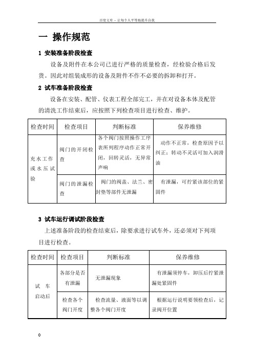
一操作规范1 安装准备阶段检查设备及附件在本公司已进行严格的质量检查,经检验合格后发货。
因此对组装成形的设备及附件不作不必要的拆卸和打开。
2 试车准备阶段检查设备在安装、配管、仪表工程全部完工,并在对设备本体及配管的清洗工作结束后,应按照下列检查项目进行检查、维护。
3 试车运行调试阶段检查上述准备阶段的检查结束后,除要求进行试车外,还必须对下列项目进行检查。
检查各处压力值各个压力表点压力示值正常压力异常,及时采取处理措施4 开机准备检查过滤器本体及附属的各种阀门、管路、仪表和各种设备附件是否完好;检查絮凝剂加药计量箱中药液是否充足;计量泵是否完好;检查原水泵、电气设备、各种现场仪表及各种附属设施是否完好;确认各种排放、正洗、反洗等阀门已关闭;过滤器排气阀门见水后关闭;5、开机运行运行工作流程:排气→冲洗→反洗(二) →正洗→制水→反洗(一) →排水→气水擦洗└————————————←——————————┘注:长时间停运后开车,应从反冲洗(一)工序开始。
阀门:上部进水阀(D1)、出水阀(D2)、反洗排水阀(D3)、正洗排水阀(D4)、中间排水阀(D5)、下部进水阀(D6)、小反洗阀(D7)、排气阀(D8)、进压缩空气阀(D9)。
《见下图》1)运行:打开上部进水阀D1、下部D6 和出水阀D2 ,闭其余阀门。
设备进入产水状态。
注意D1和D2 阀的开启度应基本相同,保证上部和下部进相同。
当设备运行的进、出水的压力差达时,过滤器应进行反洗。
※初次或停运很长时间时,应对滤层进行清洗。
方法与反冲清洗相同(详见下反冲步骤)。
2)反洗:采用水反冲洗、空气辅助擦洗方式。
气反洗:打开上部排水阀D4,再缓慢打开进压缩空气阀D9,压缩空气的压力为不小于。
气反洗进气量(约min),通过D9 阀调节,对滤料进行松动擦洗。
气反洗时间为3min,然后关闭D9 阀门。
水反冲洗:上排阀始终为开启状态、开启反冲洗阀D3,由下部进水对滤层进行反冲洗,水反冲洗量(约min),时间约为5min,然后关闭D3 阀,同时开启小反洗阀D7,对上部滤料滤层进行反冲洗。
Installation & Service Instructions: 2M100D Modular KitsISSUED: September, 2006 Supersedes: November, 2003Doc.# 2M100, ECN# 060870, Rev. 6Pneumatic DivisionRichland, Michigan 49083269-629-5000IntroductionFollow these instructions when installing, operating, or servicing theproduct.05 SeriesA 4.33(110)A 16.38(162)B 5.35(136)C 3.15(80)D 2.05(52)E 8.50(216)F 1.45(37)G 2.60(66)H 1.14(29)J 4.72(120)06 SeriesA 6.10(155) A 19.04(230)B 5.69(145)C 4.69(119)D 3.18(81)E 10.38(264)F 2.00(51)G 3.58(91)H 1.40(36)J 6.65(169)07 SeriesA 7.00(178) A 110.28(261)B 6.97(177)C 4.79(122)D 3.44(87)E 11.76(299)F 2.18(55)G 3.58(91)H 1.40(36)J 7.51(191)Inches (mm)• All dimensions nominal.Bowl guards are recommended for added protection of polycarbonate bowls where chemical attack may occasionally occur.! WARNINGTo avoid polycarbonate bowl rupture that can cause personal injury or property damage, do not exceed bowl pressure or temperature ratings. Polycarbonate bowls have a 150 PSIG pressure rating and a maximum temperature rating of 125°F.WARNINGFAILURE OR IMPROPER SELECTION OR IMPROPER USE OFTHE PRODUCTS AND/OR SYSTEMS DESCRIBED HEREIN ORRELATED ITEMS CAN CAUSE DEATH, PERSONAL INJURY AND PROPERTY DAMAGE.This document and other information from The Company, its subsidiaries and authorized distributors provide product and/or system options for further investigation by users having technical expertise. It is important that you analyze all aspects of your application, including consequences of any failure and review the information concerning the product or systems in the current product catalog. Due to the variety of operating conditions and applications for these products or systems, the user, through its own analysis and testing, is solely responsible for making the final selection of the products and systems and assuring that all performance, safety and warning requirements of the application are met.The products described herein, including without limitation, product features, specifications, designs, availability and pricing, are subject to change by The Company and its subsidiaries at any time without notice.EXTRA COPIES OF THESE INSTRUCTIONS ARE AVAILABLE FOR INCLUSION IN EQUIPMENT / MAINTENANCE MANUALS THAT UTILIZE THESE PRODUCTS. CONTACT YOUR LOCAL REPRESENTATIVE.! WARNINGT o avoid unpredictable system behavior that can cause personalinjury and property damage:• Disconnect electrical supply (when necessary) before installation, servicing, or conversion.• Disconnect air supply and depressurize all air lines connected to this product before installation, servicing, or conversion.• Operate within the manufacturer’s specified pressure, temperature, and other conditions listed in these instructions.• Medium must be moisture-free if ambient temperature is below freezing.• Service according to procedures listed in these instructions.• Installation, service, and conversion of these products must be performed by knowledgeable personnel who understand how pneumatic products are to be applied.• After installation, servicing, or conversion, air and electrical supplies (when necessary) should be connected and the product tested for proper function and leakage. If audible leakage is present, or the product does not operate properly, do not put into use.• Warnings and specifications on the product should not be covered by paint, etc. If masking is not possible, contact your local representative for replacement labels.! CAUTION Polycarbonate bowls, being transparent and tough, are ideal for use withFilters and Lubricators. They are suitable for use in normal industrial environments, but should not be located in areas where they could be subjected to direct sunlight, an impact blow, nor temperatures outside of the rated range. As with most plastics, some chemicals can cause damage. Polycarbonate bowls should not be exposed to chlorinated hydrocarbons, ketones, esters and certain alcohols. They should not be used in air systems where compressors are lubricated with fire-resistant fluids such as phosphate ester and diester types.Metal bowls are recommended where ambient and/or media conditions are not compatible with polycarbonate bowls. Metal bowls resist the action of most such solvents, but should not be used where strong acids or bases are present or in salt laden atmospheres. Consult the factory for specific recommendations where these conditions exist.TO CLEAN POL YCARBONATE BOWLS USE MILD SOAP AND WATER ONL Y! DO NOT use cleansing agents such as acetone, benzene, carbon tetrachloride, gasoline, toluene, etc., which are damaging to this plastic.!Safety GuideFor more complete information on recommended application guidelines, see the Safety Guide section of Pneumatic Division catalogs or you can download the Pneumatic Division Safety Guide at: /safetyTorque T o Torque T o 3.4 - 4.5 Nm (30 - 40 In. Lb.)Modular Kits 2M100DInstallationAttach inner clamp to wall bracket using the screw provided. See Figures 1 & 2 for screw torque values. Mount wall bracket to wall using spacing shown in Figure 3. The wall brackets are designed to use 1/4 inch screws. Attach the port blocks to pipe threads using a small amount of thread sealant. Position the port blocks with two bumps pointing down (06 & 07 Series). The unit will leak if the port blocks are not positioned properly. Assemble each inner and outer clamp with the tube seal and spacer installed as shown. The inner and outer clamp must be installed with proper orientation as shown in Figures 1 & 2. Install the clamp screws with one thread of engagement. Position the filter, regulator, or lubricator with the angled surface of body ears engaged with the angled surface of the inner and outer clamp. The regulator must be installed with knob pointing down. The filter/regulator must be installed with the knob pointing up. Tighten the clamp screws alternating between the two screws per connector until both screws are snug. Check the alignment of each body to verify fit between body and clamp. The bottom flange of the inner and outer clamp must be positioned below the bottom edge of the body. Pressurize the assembly and check for air leaks. If air leaks are found, depressurize the unit. Loosen the outer clamp and check fit between the body and clamps. Retighten the screws and check for air leaks.RemovalDisconnect air supply and depressurize all air lines before removing any modular units.! WARNINGLoosening the outer clamp screws may cause the filter, regulator, lubricator, or accessory to dislodge and fall. It is important to take necessary precautions when loosening the outer clamp screws to prevent the unit from falling and causing injury.Loosen the outer clamp screws 8-9 turns. It is not necessary to completely remove the screws. Slide the unit down until it disconnects from the clamps. It may be necessary to pull the outer clamp out when removing one of the units from the assembly.Figure 3 (06-07 Series)Torque T Assemble T o Bodies Or Port Blocks And Torque To 2.8 - 3.4 Nm (25 - 30 In. Lb.)05 SeriesA 6.70(170)A 18.72(222)B 5.35(136)C 2.24(57)D 2.05(52)E 7.59(193)F 1.45(37)G 2.60(66)H 1.14(29)J 2.35(600)06 SeriesA 9.46(240) A 112.39(315)B 5.69(145)C 2.24(57)D 3.18(81)E 7.82(199)F 2.00(51)G 3.58(91)H 1.40(36)J 3.33(85)07 SeriesA 10.750(273) A 114.03(356)B 6.97(177)C 2.41(61)D 3.44(87)E 9.27(235)F 2.18(55)G 3.58(91)H 1.40(36)J 3.76(95)Inches (mm)• All dimensions nominal.Figure 1 (05 Series)。
设备运行程序设备正常工作时,按下列顺序循环运行:重复1次加水过滤(过滤排放) 准备 排水 气洗 水洗 静置设备是从加水过滤状态开始,运行完设定的时间后,进入反冲洗状态直至加水过滤状态完成一个循环周期。
自动运行:自动过滤把选择开关打到“A罐”“自动运行”,按下“状态确认”,A罐进入自动过滤状态,选择开关打到“B罐”“自动运行”,按下“状态确认”,B罐进入自动过滤状态,此时C罐默认为备用状态。
过滤时间为11小时20分钟,其中排油间隔为3小时58分钟,开启2分钟。
(A罐第一次过滤10小时39分钟后进入反洗)自动反洗当过滤计时到,进入反洗。
当A罐/B罐进入反洗时,C罐(备用)进入过滤状态,当A罐/B罐反洗结束后,C重新返回备用状态,反洗罐返回过滤状态。
当系统运行1周左右时,需对备用罐进行更换。
在A罐/B罐过滤时,选择开关打到“B罐”“自动”,按下“状态复位”B罐进入备用状态,选择开关打到“C罐”“自动”,按下“状态确认”,然后按下“强制反洗”,对 C罐进行清洗。
C罐反洗结束后,自动进入过滤状态。
1周后,对C罐复位,选择B罐自动,并进行强制反洗,以保证出水水质。
手动运行:设备的手动操作仅用于设备开机调试及设备检修。
控制柜面板上设置有“自动/停/手动”系统运行状态选择旋钮、“A罐/B罐/C罐” 过滤器罐号选择旋钮、“风机A/风机B”反洗风机选择旋钮、自动阀门及风机电机的手动操作按钮。
当设备在手动运行模式下运行时,除手动阀门直接使用阀门手柄操作外,自动阀门的启/闭及电机的启/停都可以通过控制柜操作面板上的按钮进行操作。
下面以A罐为例,说明手动操作的步骤。
·进水排空将系统运行状态选择旋钮“自动/停/手动” 置于“手动”位置,过滤器罐号选择旋钮“A罐/B罐/C罐”置于“A罐”位置,风机选择旋钮“风机A /风机B”置于“风机A”位置,按“状态确认”按钮,过滤器A罐进入手动操作模式。
按“排油阀开/关”、“过滤进水阀开/关”、“过滤出水阀开/关”按钮,过滤器A罐的排油阀(KV3112A)、过滤进水阀(KV3107A)、过滤出水阀(KV3110A)打开,且对应的阀门指示灯亮,过滤器开始进水,调节过滤进出水手动阀门的开启度,确保排除容器和管汇中空气,使容器整个腔内充满水,待排油阀(KV3112A)有水溢出时,按“排油阀开/关”、“过滤进水阀开/关”、“过滤出水阀开/关”按钮,过滤器A罐的排油阀(KV3112A)、过滤进水阀(KV3107A)、过滤出水阀(KV3110A)关闭,且对应的阀门指示灯灭,A罐进水结束。
《生产作业指导书》39型管道过滤器生产
1.目的
为使39型管道过滤器组装的生产流程符合本公司程序文件的要求,39型管道过滤器组装的生产处于规范状态,特制定此指导书。
2.范围
本办法适用于39型管道过滤器组装的生产。
3.职责
3.1工艺部门负责作业指导书的编制和管理。
3.2质量管理部门负责对作业指导书的执行进行监督。
3.3生产员工应在整个生产过程中严格执行作业指导书的规定,现场主管配合质量部
门负责对整个执行过程进行监督。
4.工作程序
质控点操作检查检查3
质控点操作检查
质控点操作检查
质控点操作检查
管道式过滤器
质控点操作检查
质控点操作检查
质控点操作检查附表1:
法兰重要特性尺寸表
螺口重要特性尺寸表
.
附图1
标 贴 位 置 图
5.质量记录。
This manual is effective for all filters of the type DU40 and related specifications. It contains certain requirements and instructions which ensure unobjectionable operation of the filter. It can be completed with specific additional instructions by the operator himself if necessary.1. Safety instructions- The operating and maintenance instructions must be read carefully before working on the filter.- The instructions in this manual must be followed!- The manufacturer assumes no liability for damage caused by deviations from this manual..- If actions are performed differently than described, the safety of the pressure equipment is not guaranteed!- The operating parameters specified in the data sheet, in particular operating pressure, operating temperature range and operating medium, must be observed. Deviations from these parameters can damage pressure-bearing parts and seals. The compatibility of the filter components with the operating medium must be observed.- The filter is under pressure in the operating state. No components of the filter may be loosened or removed during operation. Operating medium can escape under high pressure and at high temperature.This does not include components on the pressure-relieved or switched-off side of the housing.- There is a risk of injury and scalding from the operating medium escaping!- The filter housing must not be opened before it is ensured that it is no longer under pressure!- Touching components of the filter can cause burns, depending on the operating temperature.- Attention when changing the filter elements! Filter housing might still have operating temperature. Risk of burn!- Always wear protective gloves and safety glasses when working on the filter!- If you come into contact with the operating medium, the manufacturer's instructions must be observed!- Only original spare parts may be used.For filters being used in hazardous locations the Eaton documentation N° 41269 "Supplementation of the Operating Manual for the use of filters in potential explosive areas.2. AssemblyThe filter is delivered ready for installation. The filter has to be fitted according to the fitting position the corresponding data sheet on a flat vertical surface.The fitting of the filter has to be carried out in the way that the least possible transmission of tensible forces on the filter housing is given.Ensure upon assembling that1. no dirt and no impurities of foreign fluids penetrate the filter,2. the connection for input and output are correctly connected to the pipe system,3. the pipe system is connected with the filter; as stress free as possible,4. the extension to demount and the accessibility to the service elements is quaranted.Filter with electrical respectively electronic clogging indicators have to be installed according to the unit specific conditions and according to the technical parameters of the corresponding data sheets.3. CommissioningBefore commissioning the completeness of the filter (filter elements and seals) and the clean ness have to be controlled.Air bleeding of the controlled filter has to be carried out according to the following instructions:1 The positioning pin of the selector shaft has to be located in the middle position2. Connection of high-pressure hoses M16 according to data sheet 1650 with connections III and IV, if these areequipped with screw couplings, or connection of suitable ventilation lines to the thread G ¼“(BSPP ½”) of the above. Connections after unscrewing the screw plugs3. Provision of an intercepting tank for the discharging medium4. Connection of the unit volume flow (reduced volume flow; from <10 l/min (2.64 gpm/min)) until bubble-freeoperating fluid flows out of both air bleeding tubes5. Disconnection of the unit volume flow6. Remove the air bleeding tubes and close the air-bleed bore holes or air-bleed connections (air-bleed connectionsaccording to data sheet 1651)7. Connection to the required filter side at the positioning pin of the selector shaftThe positioning pin of the selector shaft shows always in direction to the operating filter side.The air bleeding has to be done parallel at all filters in the case of paralleling filters.EDV 05/23_EN Subject to change.4. Change of elementThe changing of the filter elements is necessary when reaching the unit specific pressure difference respectively reaching the maximum pressure difference given by the clogging indicator. If should is no unit specific definition, the change of the elements should be done at a maximum of p = 6 bar (87 PSI).This has to be carried out as follows:1. Switching over the positioning pin from the operating side to the other side2. At the serviced filter side the connection III or IV has to be opened by connecting a high pressure tube M16according to data sheet 1650 or should be connected to a suitable air-bleed line if no screw fittings are present. A vessel should be held ready to catch the emerging fluid3. Unscrew the filter bowl4. Remove the filter elements5. Clean the filter bowl6. Replace the new or the cleaned filter elements7. Screw the filter bowl back on and tighten it. (tightening torque 80 Nm)8. Close up any outletsNow, the serviced filter side is ready for operation.In general take care of the absolute cleanness during the changing of elements. No dirt respectively no impurities should penetrate the filter. The new elements should be taken out of their packing shortly before they are replaced in the filter housing because of mechanical damage. During the changing of the elements control the availability and quality of the seals. Damaged seals have to be replaced be new ones.5. Cleaning of the filter elementFilter elements with filter materials such as glass fiber (VG) are not cleanable. They have to be replaced after the dirt retention capacity has been reached. Filter elements with filter material such as wire mesh (G) are cleanable and could be used again.The cleaning of the filter elements has to be done according to the cleaning specification for Eaton-filter elements (metal), sheet-no. 21070-4 and 39448-4.6. Pressure difference measuringIn case of filters installed with clogging indicators a permanent measuring of the pressure difference takes place. The indication corresponds to the kind of clogging indicators; either visual or visual-electrical respectively electronic. Additionally the connections III and IV could be installed on the selector shaft to be used for external pressure gaugesfor Eaton double filter, change-over DU 40, related specifications7. Change of sealings8. ServiceThe service will be performed byEATON Technologies GmbH Friedensstr. 41D-68804 Altlußheim Germanyphone: +49(0)6205-2094-0 fax: +49(0)6205-2094-40Special questions about the operation of the filter will also be answered within this area.Spare parts respectively wearing parts have to be ordered according to the spare part list of the filter-data-sheet.32885-4EPage 3/31. Disassemble the filter bowl (item 1).Remove and replace O-ring 54x3 (item 2) and support ring 60x2,6x1 (item 3). Assemble and tighten the filter bowl. (tightening torque 80 Nm (59 lb.-ft.))2. Loosen the screws (item 8) and remove the cover (item 9) and the lever (item 10/11).Remove and replace the O-ring 23x3 (item 4) and the support ring 28x3.6x1 (item 5). Assemble the cover and lever and tighten the screws.(tightening torque 18-20 Nm (13 to15 lb.-ft.))3. Loosen the screws (item 12) and remove the plate (item 13).Remove and replace the O-ring 32.9x3.53 (item 6).Assemble the plate and tighten the screws. (tightening torque 18-20 Nm (13 to15 lb.-ft.))。
双联过滤器说明书
一.适用范围:
SLG型双联过滤器主要应用于化工,石油化工生产中的弱腐蚀性物料,如:水、氨、油品、烃类等。
化工生产中的腐蚀性物料,如:烧碱、浓稀硫酸、碳酸、醋酸等。
制冷中的低温物料,如:液甲烷、液氨、液氧和各种冷剂。
轻工食品,制药生产中有卫生要求的物料,如:啤酒、饮料、乳制品、粮浆医药用品等。
二.结构特点:
双联切换过滤器是一种由两台不锈钢袋式过滤器并联而成,顶部装有放气口和放气阀,上盖和滤筒连接采用法兰连接结构。
在系统不停运的情况下通过转换三通阀门可以方便拆换滤网。
具有结构新颖合理、密封性好、流通能力强、可以连续工作,操作简便等多优点,是一种应用范围广泛、适应性强的多用途过滤设备。
尤其是滤袋侧漏几率小,能准确地保证过滤精度,并能快捷地更换滤袋,过滤基本无物料消耗,运行成本低。
三.结构原理:
本设备全部采用不锈钢SUS304/316L制造,滤筒内装有不锈钢滤网和滤网支撑篮;顶部装有放气阀,供过滤时排放滤器内空气用。
三只支脚可使滤器平稳放置在地面上。
连接管路采用焊接,紧固耐用。
进出料阀门采用三通球阀启闭,耐压耐温,操作灵活方便,无料液泄漏更卫生。
管道接头采用胀合连接,经1.6Mpa 水压试验,三通阀启闭灵活,该设备结构滤材、过滤器选型紧凑,操作方便,维修简单。
此外:可将两个单筒过滤器组装在一个机座上,清洗过滤器时不必停车,保证其连续工作,是不停车生产线过滤装置首选。
四.技术参数:
产品执行标准:GB/T9119-2010
过滤精度:100μm,
滤网材质:316不锈钢,
最高设计压力:1.6Mpa,。