双联可切换过滤器操作指导书
- 格式:doc
- 大小:2.37 MB
- 文档页数:13
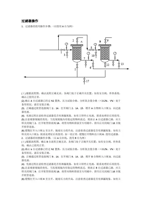
过滤器操作1.过滤器的投用操作步骤:(以投用A台为例)(1).根据流程图,确认流程正确无误,各阀门处于正确开关位置;如有安全阀、伴热系统,确认已投用正常。
(2).确认A台过滤器已经过N2置换,压力试验合格,分析氧含量合格(≤0.2%,V%)处于备用状况,滤芯安装正确。
(3). 正确通过软管连接阀门2、14,打开阀门2、14、15,稍开A台物料入口阀1,向过滤器充液。
(4). 充液过程注意检查过滤器是否有泄漏现象,如有立即停止充液,联系处理好后再投用。
(5).注意观察视镜的变化,当发现视镜内有稳定的物料流过,则表示A台过滤器已满,应立即关闭阀门2,打开软管排放阀16,将管内物料排放至专用桶中,排尽后关闭阀门16并脱开软管连接。
(6).缓慢打开入口阀1至全开,随着压力的升高,注意检查过滤器是否有泄漏现象,如有立即关闭入口阀1,联系处理好后再投用。
如一切正常,缓慢打开物料出口阀6,投用过滤器。
2.过滤器的切换操作步骤:(以A台在线,投用B台为例)(1).根据流程图,确认B台流程正确无误,各阀门处于正确开关位置;如有安全阀、伴热系统,确认已投用正常。
(2).确认b台过滤器已经过N2置换,压力试验合格,分析氧含量合格(≤0.2%,V%)处于备用状况,滤芯安装正确。
(3). 正确通过软管连接阀门9、14,打开阀门9、14、15,稍开B台物料入口阀8,向过滤器充液。
(4). 充液过程注意检查过滤器是否有泄漏现象,如有立即停止充液,联系处理好后再投用。
(5).注意观察视镜的变化,当发现视镜内有稳定的物料流过,则表示B台过滤器已满,应立即关闭阀门9,打开软管排放阀16,将管内物料排放至专用桶中,排尽后关闭阀门16并脱开软管连接。
(6).缓慢打开入口阀8至全开,随着压力的升高,注意检查过滤器是否有泄漏现象,如有立即关闭入口阀1,联系处理好后再投用。
如一切正常,缓慢打开物料出口阀13,投用B台过滤器。
(7). 检查确认B台过滤器运行正常后,缓慢关闭A台过滤器物料出口阀门6,将A台离线。
多介质过滤器操作规程
《多介质过滤器操作规程》
一、操作前的准备
1. 检查多介质过滤器的外观是否完好,有无破损或渗漏现象;
2. 检查进水、出水管道及阀门是否正常;
3. 检查多介质过滤器的底阀是否关闭;
4. 准备必要的操作工具和材料。
二、操作步骤
1. 打开多介质过滤器的进水阀门,注入适量的水;
2. 打开多介质过滤器的进水阀门,放慢水流速度,使介质均匀分布;
3. 液位上升到一定高度后,关闭进水阀门;
4. 打开多介质过滤器的排水阀门,释放水中的杂质和空气;
5. 多介质过滤器运行一段时间后,打开排水阀门,排出残余的空气和水渣;
6. 检查多介质过滤器的压差表,如压差过大,需要清洗或更换过滤介质。
三、操作注意事项
1. 操作时需穿戴好个人防护用具,注意安全;
2. 严禁在多介质过滤器开启状态下进行维护操作;
3. 定期清理多介质过滤器,保持过滤效果;
4. 严格按照操作规程进行操作,不得擅自改变运行参数。
四、操作结束
1. 关闭多介质过滤器的进水和排水阀门;
2. 清洗和存储操作工具;
3. 记录多介质过滤器的运行参数和操作情况;
4. 定期进行设备维护和检查。
以上便是多介质过滤器操作规程的基本要点,希望大家在操作时能够严格按照规程进行,确保多介质过滤器的正常运行和过滤效果。
过虑器操作规程过滤器操作规程第一章总则第一条为保障过滤器的正常运行和使用,防止操作中的事故发生,特制定本操作规程。
第二条本操作规程适用于所有使用过滤器的人员。
第二章运行与检查第三条在运行过滤器前,应检查过滤器的部件是否完好无损,如有损坏或松动应及时进行修复或更换。
第四条检查过滤器的过滤网和滤芯是否干净,如有污垢应及时清理或更换。
第五条检查过滤器的电源线是否正常,接好地线后方可运行。
第六条在运行过程中,应经常检查过滤器的过滤效果,如发现效果不理想,应及时排查原因并进行修复。
第三章操作规范第七条操作过滤器应经过专门培训,掌握操作技能和必要的安全知识。
第八条在操作过滤器前,应戴好防护眼镜、口罩、手套等个人防护用品。
第九条在操作过滤器时,应保持工作环境整洁,防止杂物进入过滤器内部。
第十条操作过滤器时,应按照正确的操作步骤进行,不得随意更改或增减操作内容。
第十一条操作过滤器时,应严格按照设定的运行参数进行操作,不得擅自调整或改变参数设置。
第十二条操作过滤器时,应掌握相应的控制手段和操作技巧,确保过滤器的正常运行。
第十三条在操作过滤器时,应遵守相关的操作规程和安全操作指南,保证操作的安全性。
第十四条在操作过滤器时,应及时记录相关数据和操作情况,以备后续查询和分析。
第十五条在操作过滤器时,应注意观察过滤器的运行状态,如发现异常情况应及时停机进行排查和处理。
第十六条在操作过滤器时,应定期进行设备维护和保养,确保设备的长期稳定运行。
第四章安全措施第十七条在操作过滤器时,应保持操作人员和设备之间的安全距离,防止意外发生。
第十八条在操作过滤器时,应切断电源,拔掉电源插头,确保设备的停电状态后方可进行检修、维护和清洁。
第十九条在操作过滤器时,应关闭相关设备的阀门和开关,确保一切就绪后方可操作。
第二十条在操作过滤器时,应防止水源或电源进入设备内部,以免引发电击或事故。
第二十一条操作过滤器时,应注意操作台的稳定性,防止设备的滑动或倾倒。
多介质过滤器(1)概述本过滤器适用于较大规模的给水和废水过滤处理及循环水的旁滤处理,具有占地面积小、操作简单、不易出故障等特点。
在循环供水系统中使用可改善水质,提高水的循环利用率、达到节约用水的目的。
(2)结构及工艺流程①设备结构过滤器本体主要由壳体、布水器、滤料、滤板及滤帽、布气器、收水器、支腿(或支座)等组成。
②工艺流程A、过滤原水通过过滤器进水口进入布水器,原水中的悬浮物和水一起通过滤层进行过滤,由于滤料的级配颗粒上层大下层小,缝隙沿程变小,截污能力沿程变大。
污水中的颗粒悬浮物被滤层阻挡、吸附在滤料表面,从而实现过滤的目的,通过过滤后的水由设在滤板上的滤帽收集进入下部的清水区,通过出水口排出,从而完成整个处理过程(为了防止石英砂滤料堵塞滤帽,在石英砂下面铺有卵石垫层)。
B、反冲洗当过滤器工作压力比初期高出0。
05MPa时,说明滤料表面集污较多,阻力增大,过滤器需进行反冲洗,关闭过滤进水阀和过滤出水阀,打开过滤器反洗排污阀,排水数分钟使得过滤器内水位降至上视镜中部。
打开反洗进气阀进行气洗,气体将由滤帽杆的下部口进入,通过滤帽均匀分布,滤料在气体的推动下进行膨胀,高强度的相互磨擦,从而达到高强度的气体与水混合冲洗滤料的目的,气洗完毕后关闭反洗进气阀.打开反洗进水阀进行水反洗至排水不浑浊,静止2分钟完成反洗流程,过滤器进入正洗。
C、正洗为保证过滤出水水质,反洗完毕后,正洗3-5分钟至排水清澈。
(4)安装要求罐体直径小于4米的设备,整机出厂,现场安装要求如下:①基础为预埋地脚螺栓设备根据设计图纸检查基础合格报告必须满足设备运行荷载的要求.●∙根据设计图纸检查基础预留孔中心及尺寸。
●∙根据设计图纸检查基础水平度。
●∙将设备预装到位,在底座下垫钢板找平,地脚螺栓安装在设备底座上,确认地脚螺栓的安装位置,并二次灌浆将预留孔填满。
●∙安装外部管线。
●∙按滤料级配划线,装填滤料,滤料表面应平整,约高于装填高度。
双联过滤器使用说明书制作单位:生产基地:公司电话:公司传真:邮编:编制日期:目录一、产品介绍 (3)二、工作原理 (3)三、设备技术参数 (4)四、售后服务承诺 (5)五、合格证 (6)一、产品介绍:双联过滤器(双联切换过滤器)是一种由两台不锈钢袋式过滤器并联而成,具有结构新颖合理、密封性好、流通能力强、可以连续工作,操作简便等诸多优点,应用范围广泛、适应性强的多用途过滤设备。
尤其是滤袋侧漏机率小,能准确地保证过滤精度,并能快捷地更换滤袋,过滤基本无物料消耗,使得操作成本降低。
二、结构原理:本设备全部采用不锈钢SUS304/316L制造,内外表面抛光处理,滤筒内装有不锈钢滤网和滤网支撑篮;顶部装有放气阀,供过滤时排放滤器内空气作用。
上盖与滤筒连接采用快开式结构,更方便清洗(更换)滤网,三只可调节式支脚可使滤器平稳放置在地面上。
连接管路采用活接或卡箍连接方式,进出料阀门采用三通球阀启闭,耐压耐温,操作灵活方便,无料液泄漏更卫生。
管道接头采用胀合连接,经水压试验,三通外螺纹旋塞启闭灵活,该设备结构紧凑,操作方便,维修简单。
此外:可将两个单筒过滤器组装在一个机座上,清洗过滤器时不必停车,保证其连续工作,是不停车生产线过滤装置首选。
三、设备技术参数:四、售后服务承诺:1)及时向需方提供按合同规定的全部技术资料各图纸,有义务在必要时邀请需方参与供方的技术设计审查。
2)按需方要求的时间到现场进行技术服务,指导需方按供方的技术资料各图纸要求进行安装、分部与整套试运及试生产。
3)对于需方选购的与合同设备有关的配套设备,供方应主动提供满足设备接口要求的技术条件各资料。
4)严格执行供需双方就有关问题如开会议的纪要或签订的协议。
5)根据需方的要求为需方举办有关设备安装、调试、使用、维护技术的业务培训,保证需方运行、维修人员熟练掌握运行各维修技能。
6)加强售前、售中、售后服务,把“24小时服务”,“超前服务”,“全过程服务”,“终身服务”贯彻在产品制造,安装、调试、大修的全过程。
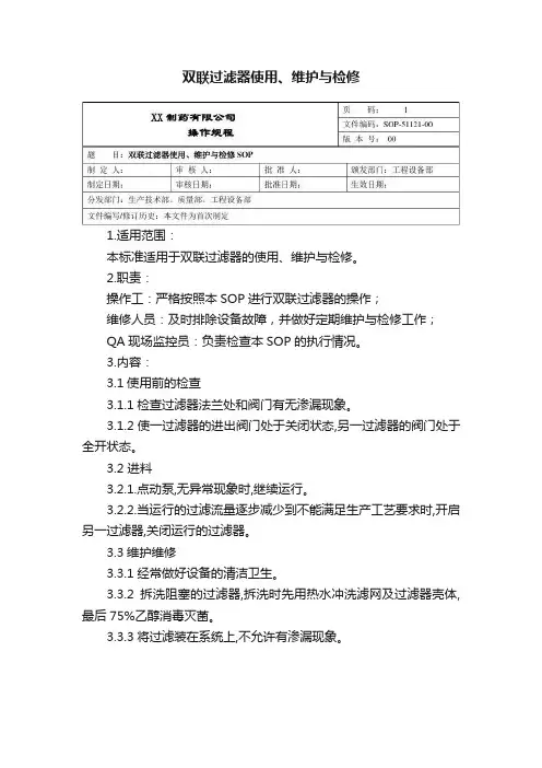
双联过滤器使用、维护与检修
1.适用范围:
本标准适用于双联过滤器的使用、维护与检修。
2.职责:
操作工:严格按照本SOP进行双联过滤器的操作;
维修人员:及时排除设备故障,并做好定期维护与检修工作;
QA现场监控员:负责检查本SOP的执行情况。
3.内容:
3.1使用前的检查
3.1.1检查过滤器法兰处和阀门有无渗漏现象。
3.1.2使一过滤器的进出阀门处于关闭状态,另一过滤器的阀门处于全开状态。
3.2 进料
3.2.1.点动泵,无异常现象时,继续运行。
3.2.2.当运行的过滤流量逐步减少到不能满足生产工艺要求时,开启另一过滤器,关闭运行的过滤器。
3.3维护维修
3.3.1经常做好设备的清洁卫生。
3.3.2拆洗阻塞的过滤器,拆洗时先用热水冲洗滤网及过滤器壳体,最后75%乙醇消毒灭菌。
3.3.3将过滤装在系统上,不允许有渗漏现象。
双联切换式过滤器安全操作规定引言双联切换式过滤器是一种常见的过滤器,广泛用于液体分离和粉尘过滤。
由于操作中会接触到一些化学品和高温物质,因此需要特别注意安全操作规范。
本文旨在提供安全操作准则,以确保人身安全和设备的高效运行。
适用范围本文适用于使用双联切换式过滤器操作的所有人员,包括设备操作人员和维护人员。
操作规范正常操作1.操作人员应该对设备的结构和原理有足够的了解,并严格按照操作流程进行操作。
2.在使用过滤器前,应该检查主机和附属设备,确保设备无缺损、无异味。
3.操作前应该戴好安全手套、口罩和眼镜,避免吸入有害气体。
4.设备应该设置在平稳坚固的地面,以避免设备晃动、翻倒等安全事故。
5.操作人员应该稳定情绪,严格按照规定操作时间和顺序。
6.操作过程中,严禁离开设备,注意观察过滤器状态,及时发现并解决故障。
废料处理1.废液体和废渣应该及时处理,不得乱倒乱扔。
2.废液体应该妥善储存,防止溢漏污染环境,禁止倒入公共下水道或河流。
3.废渣应该集中存储,按规定分类处理,防止危害人体和环境。
设备维护1.操作人员应对设备进行定期维护,及时更换损坏零件和防尘滤网。
2.在进行维护时,先关闭设备电源,待设备停止运行后再进行操作。
3.维护操作要正确,避免误操作损坏设备。
4.维护完成后,要将设备部件按原位置安装好,并按照程序重新启动设备。
安全提示1.操作过程中,严禁戴有项链、手表、戒指等物品,以免发生危险。
2.操作人员应该定期参加安全培训和应急演练。
3.在操作过程中,如发现异常操作现象及时上报,不可瞒报、漏报事故。
4.紧急情况下,应迅速切断设备电源或紧急停车按钮并立即报警。
总结安全是企业的命脉,如何确保设备和人员的安全,是企业管理者必须重视的问题。
本文详细描述了双联切换式过滤器的安全操作规定,旨在提醒操作人员要时刻注意自身安全,并遵循本文所述操作规范。
同时,也希望企业管理者加强安全教育和管理,为企业的健康发展提供保障。
设备运行程序设备正常工作时,按下列顺序循环运行:重复1次加水过滤(过滤排放) 准备 排水 气洗 水洗 静置设备是从加水过滤状态开始,运行完设定的时间后,进入反冲洗状态直至加水过滤状态完成一个循环周期。
自动运行:自动过滤把选择开关打到“A罐”“自动运行”,按下“状态确认”,A罐进入自动过滤状态,选择开关打到“B罐”“自动运行”,按下“状态确认”,B罐进入自动过滤状态,此时C罐默认为备用状态。
过滤时间为11小时20分钟,其中排油间隔为3小时58分钟,开启2分钟。
(A罐第一次过滤10小时39分钟后进入反洗)自动反洗当过滤计时到,进入反洗。
当A罐/B罐进入反洗时,C罐(备用)进入过滤状态,当A罐/B罐反洗结束后,C重新返回备用状态,反洗罐返回过滤状态。
当系统运行1周左右时,需对备用罐进行更换。
在A罐/B罐过滤时,选择开关打到“B罐”“自动”,按下“状态复位”B罐进入备用状态,选择开关打到“C罐”“自动”,按下“状态确认”,然后按下“强制反洗”,对 C罐进行清洗。
C罐反洗结束后,自动进入过滤状态。
1周后,对C罐复位,选择B罐自动,并进行强制反洗,以保证出水水质。
手动运行:设备的手动操作仅用于设备开机调试及设备检修。
控制柜面板上设置有“自动/停/手动”系统运行状态选择旋钮、“A罐/B罐/C罐” 过滤器罐号选择旋钮、“风机A/风机B”反洗风机选择旋钮、自动阀门及风机电机的手动操作按钮。
当设备在手动运行模式下运行时,除手动阀门直接使用阀门手柄操作外,自动阀门的启/闭及电机的启/停都可以通过控制柜操作面板上的按钮进行操作。
下面以A罐为例,说明手动操作的步骤。
·进水排空将系统运行状态选择旋钮“自动/停/手动” 置于“手动”位置,过滤器罐号选择旋钮“A罐/B罐/C罐”置于“A罐”位置,风机选择旋钮“风机A /风机B”置于“风机A”位置,按“状态确认”按钮,过滤器A罐进入手动操作模式。
按“排油阀开/关”、“过滤进水阀开/关”、“过滤出水阀开/关”按钮,过滤器A罐的排油阀(KV3112A)、过滤进水阀(KV3107A)、过滤出水阀(KV3110A)打开,且对应的阀门指示灯亮,过滤器开始进水,调节过滤进出水手动阀门的开启度,确保排除容器和管汇中空气,使容器整个腔内充满水,待排油阀(KV3112A)有水溢出时,按“排油阀开/关”、“过滤进水阀开/关”、“过滤出水阀开/关”按钮,过滤器A罐的排油阀(KV3112A)、过滤进水阀(KV3107A)、过滤出水阀(KV3110A)关闭,且对应的阀门指示灯灭,A罐进水结束。
《生产作业指导书》39型管道过滤器生产
1.目的
为使39型管道过滤器组装的生产流程符合本公司程序文件的要求,39型管道过滤器组装的生产处于规范状态,特制定此指导书。
2.范围
本办法适用于39型管道过滤器组装的生产。
3.职责
3.1工艺部门负责作业指导书的编制和管理。
3.2质量管理部门负责对作业指导书的执行进行监督。
3.3生产员工应在整个生产过程中严格执行作业指导书的规定,现场主管配合质量部
门负责对整个执行过程进行监督。
4.工作程序
质控点操作检查检查3
质控点操作检查
质控点操作检查
质控点操作检查
管道式过滤器
质控点操作检查
质控点操作检查
质控点操作检查附表1:
法兰重要特性尺寸表
螺口重要特性尺寸表
.
附图1
标 贴 位 置 图
5.质量记录。
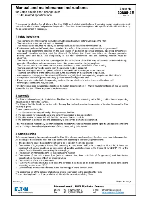
This manual is effective for all filters of the type DU40 and related specifications. It contains certain requirements and instructions which ensure unobjectionable operation of the filter. It can be completed with specific additional instructions by the operator himself if necessary.1. Safety instructions- The operating and maintenance instructions must be read carefully before working on the filter.- The instructions in this manual must be followed!- The manufacturer assumes no liability for damage caused by deviations from this manual..- If actions are performed differently than described, the safety of the pressure equipment is not guaranteed!- The operating parameters specified in the data sheet, in particular operating pressure, operating temperature range and operating medium, must be observed. Deviations from these parameters can damage pressure-bearing parts and seals. The compatibility of the filter components with the operating medium must be observed.- The filter is under pressure in the operating state. No components of the filter may be loosened or removed during operation. Operating medium can escape under high pressure and at high temperature.This does not include components on the pressure-relieved or switched-off side of the housing.- There is a risk of injury and scalding from the operating medium escaping!- The filter housing must not be opened before it is ensured that it is no longer under pressure!- Touching components of the filter can cause burns, depending on the operating temperature.- Attention when changing the filter elements! Filter housing might still have operating temperature. Risk of burn!- Always wear protective gloves and safety glasses when working on the filter!- If you come into contact with the operating medium, the manufacturer's instructions must be observed!- Only original spare parts may be used.For filters being used in hazardous locations the Eaton documentation N° 41269 "Supplementation of the Operating Manual for the use of filters in potential explosive areas.2. AssemblyThe filter is delivered ready for installation. The filter has to be fitted according to the fitting position the corresponding data sheet on a flat vertical surface.The fitting of the filter has to be carried out in the way that the least possible transmission of tensible forces on the filter housing is given.Ensure upon assembling that1. no dirt and no impurities of foreign fluids penetrate the filter,2. the connection for input and output are correctly connected to the pipe system,3. the pipe system is connected with the filter; as stress free as possible,4. the extension to demount and the accessibility to the service elements is quaranted.Filter with electrical respectively electronic clogging indicators have to be installed according to the unit specific conditions and according to the technical parameters of the corresponding data sheets.3. CommissioningBefore commissioning the completeness of the filter (filter elements and seals) and the clean ness have to be controlled.Air bleeding of the controlled filter has to be carried out according to the following instructions:1 The positioning pin of the selector shaft has to be located in the middle position2. Connection of high-pressure hoses M16 according to data sheet 1650 with connections III and IV, if these areequipped with screw couplings, or connection of suitable ventilation lines to the thread G ¼“(BSPP ½”) of the above. Connections after unscrewing the screw plugs3. Provision of an intercepting tank for the discharging medium4. Connection of the unit volume flow (reduced volume flow; from <10 l/min (2.64 gpm/min)) until bubble-freeoperating fluid flows out of both air bleeding tubes5. Disconnection of the unit volume flow6. Remove the air bleeding tubes and close the air-bleed bore holes or air-bleed connections (air-bleed connectionsaccording to data sheet 1651)7. Connection to the required filter side at the positioning pin of the selector shaftThe positioning pin of the selector shaft shows always in direction to the operating filter side.The air bleeding has to be done parallel at all filters in the case of paralleling filters.EDV 05/23_EN Subject to change.4. Change of elementThe changing of the filter elements is necessary when reaching the unit specific pressure difference respectively reaching the maximum pressure difference given by the clogging indicator. If should is no unit specific definition, the change of the elements should be done at a maximum of p = 6 bar (87 PSI).This has to be carried out as follows:1. Switching over the positioning pin from the operating side to the other side2. At the serviced filter side the connection III or IV has to be opened by connecting a high pressure tube M16according to data sheet 1650 or should be connected to a suitable air-bleed line if no screw fittings are present. A vessel should be held ready to catch the emerging fluid3. Unscrew the filter bowl4. Remove the filter elements5. Clean the filter bowl6. Replace the new or the cleaned filter elements7. Screw the filter bowl back on and tighten it. (tightening torque 80 Nm)8. Close up any outletsNow, the serviced filter side is ready for operation.In general take care of the absolute cleanness during the changing of elements. No dirt respectively no impurities should penetrate the filter. The new elements should be taken out of their packing shortly before they are replaced in the filter housing because of mechanical damage. During the changing of the elements control the availability and quality of the seals. Damaged seals have to be replaced be new ones.5. Cleaning of the filter elementFilter elements with filter materials such as glass fiber (VG) are not cleanable. They have to be replaced after the dirt retention capacity has been reached. Filter elements with filter material such as wire mesh (G) are cleanable and could be used again.The cleaning of the filter elements has to be done according to the cleaning specification for Eaton-filter elements (metal), sheet-no. 21070-4 and 39448-4.6. Pressure difference measuringIn case of filters installed with clogging indicators a permanent measuring of the pressure difference takes place. The indication corresponds to the kind of clogging indicators; either visual or visual-electrical respectively electronic. Additionally the connections III and IV could be installed on the selector shaft to be used for external pressure gaugesfor Eaton double filter, change-over DU 40, related specifications7. Change of sealings8. ServiceThe service will be performed byEATON Technologies GmbH Friedensstr. 41D-68804 Altlußheim Germanyphone: +49(0)6205-2094-0 fax: +49(0)6205-2094-40Special questions about the operation of the filter will also be answered within this area.Spare parts respectively wearing parts have to be ordered according to the spare part list of the filter-data-sheet.32885-4EPage 3/31. Disassemble the filter bowl (item 1).Remove and replace O-ring 54x3 (item 2) and support ring 60x2,6x1 (item 3). Assemble and tighten the filter bowl. (tightening torque 80 Nm (59 lb.-ft.))2. Loosen the screws (item 8) and remove the cover (item 9) and the lever (item 10/11).Remove and replace the O-ring 23x3 (item 4) and the support ring 28x3.6x1 (item 5). Assemble the cover and lever and tighten the screws.(tightening torque 18-20 Nm (13 to15 lb.-ft.))3. Loosen the screws (item 12) and remove the plate (item 13).Remove and replace the O-ring 32.9x3.53 (item 6).Assemble the plate and tighten the screws. (tightening torque 18-20 Nm (13 to15 lb.-ft.))。

输气站过滤器切换作业操作规程页码:1/5输气站过滤器切换作业操作规程输气站过滤器切换作业操作规程1 范围本标准适用于输气站过滤器切换操作。
2 规范性引用文件对规程中引用的文件进行说明。
凡是注日期的引用文件,仅所注日期的版本适用于本文件。
凡是不注日期的引用文件,其最新版本(包括所有的修改单)适用于本文件。
GB150 压力容器TSG R0004 固定式压力容器安全技术监察规程3 术语和定义3.1快开盲板用于压力管道或压力容器的圆形开口上,并能实现快速开启或关闭的一种机械装置,一般由筒体法兰、头盖、勾圈或卡箍、密封圈、安全联锁机构、开闭机构、转臂及短节(需要时)等部件构成。
4 一般要求4.1生产过程中的流程操作,必须符合国家、行业和西南管道分公司的安全规定,并执行相关的文件、制度和标准。
4.2操作人员应取得输气工操作证、压力容器特种设备操作证,熟悉本站的工艺流程,过滤器结构、原理、运行参数、操作规程和使用方法,并严格按要求执行。
4.3操作过程中按照操作票操作顺序唱票,每唱一项,操作人在相应设备上复诵,监护人确认正确后,操作人方可进行操作。
4.4对于需要上报作业计划的操作,主管人员需提交作业计划并经审批通过后方可进行操作。
5 运行操作5.1 作业前准备5.1.1准备对讲机一对,电量应充足,调至相同频率。
5.1.2准备工器具,便携式可燃气体检测仪等电量应充足,工作正常。
5.1.3填写操作票,并经作业区专业工程师或管理人员审核通过。
5.1.4操作前向北京油气调控中心申请,同意后进行操作。
5.1.5穿戴好劳动防护用品。
5.2 作业前检查5.2.1 确认现场工艺流程、阀门状态正确并与上位机一致。
5.2.2 工艺系统压力、温度等远传参数正常无报警。
5.2.3 检查过滤器等关键设备是否具备切换条件。
5.2.4检查作业环境符合要求,确保作业区域无交叉作业。
5.3 作业操作流程输气站过滤器切换操作示意图5.3.1站场远控操作1)站控室上位机远程全开备用路(B路)过滤分离器进口阀2201、出口阀2202。
双联过滤器
双联过滤器简介:
(双联切换过滤器)是一种由两台不锈钢袋式过滤器并联而成,具有结构新颖合理、密封性好、流通能力强、可以连续工作,操作简便等诸多优点,应用范围广泛、适应性强的多用途过滤设备。
尤其是滤袋侧漏机率小,能准确地保证过滤精度,并能快捷地更换滤袋,过滤基本无物料消耗,使得操作成本降低。
结构原理:
本设备全部采用不锈钢SUS304/316L制造,内外表面抛光处理,滤筒内装有不锈钢滤网和滤网支撑篮;顶部装有放气阀,供过滤时排放滤器内空气作用。
上盖与滤筒连接采用快开式结构,更方便清洗(更换)滤网,三只可调节式支脚可使滤器平稳放置在地面上。
连接管路采用活接或卡箍连接方式,进出料阀门采用三通球阀启闭,耐压耐温,操作灵活方便,无料液泄漏更卫生。
管道接头采用胀合连接,经0.3Mpa水压试验,三通外螺纹旋塞启闭灵活,该设备结构
紧凑,操作方便,维修简单。
此外:可将两个单筒过滤器组装在一个机座上,清洗过滤器时不必停车,保证其连续工作,是不停车生产线过滤装置首选。
技术参数:。
微孔过滤器ZG-10.0使用说明书制作单位:生产基地:公司电话:公司传真:邮 编:编制日期:目录一、 产品介绍 (3)二、产品特点 (3)三、滤芯的选择 (3)四、设备技术参数 (4)五、使用说明 (4)六、操作注意事项 (6)七、设备的维护与保养 (6)八、售后服务承诺 (7)九、合格证 (7)十、随机附件表 (8)一、产品介绍:本设备可用于食品、乳品、饮料、酒类、中药、化工行业的液体物料的气体的过滤。
采用折叠式滤芯,折叠式滤芯是一种先进的固定型深层过滤芯,过滤公称精度范围可以从0.1μm直600.1μm。
滤膜不受进料压力波动而影响过滤精度。
其特有的低压差,高通量、良好的过滤精度能较低的经济费用成为取代线绕式、棉饼和纸板等非固定型过滤芯的新型滤芯而深受用户欢迎。
二、产品特点:①化学相容性广、流通量大、压差低、使用寿命长。
②过滤精度范围广、选择度大、可满足各种应用场合。
③采用热熔工艺,牢固且无释放物污染产品。
三、滤芯的选择:1、滤芯的用途很广泛,滤芯的品种、规格较多,选择型号是很重要的。
根据用途可分为过滤液体和气体二种,规格大小可以分为5〃、10〃、20〃、30〃和40〃等。
工作压力一般在0.1Mpa—0.4 Mpa。
由于滤芯孔径不同,其流量也不尽相同,如0.2um—0.4 um过滤沌水的标准在300—500kg/h,如果要提高每小时的过滤量,则可以用多芯或20〃、30〃、40〃英寸组合,例如要过滤5t/h的无菌水,则可以选用0.2 um,30英寸7芯的过滤器。
若过滤杂质多且有粘度,则应添加前置预过滤设备。
气体的过滤与液体过滤稍有不同,它的过滤量以每分钟立方气体来计算。
10英寸滤芯,孔径φ0.22 um,压力在0.12 Mpa,压差在0.01 Mpa时,流量为4-6m3/min,在发酵工业上广泛应用。
2 、合适的滤芯,选用适当的孔径,若要除菌则选用0.2um-0.5um孔径的滤芯、药用针剂、抗菌素、血制品等用聚砜滤芯。
多介质过滤器操作规程(二)引言概述:多介质过滤器是一种用于水处理的常见设备,具有过滤效果好、操作简便等优点。
为了保证多介质过滤器的有效运行,操作规程的制定和遵守显得尤为重要。
本文将详细介绍多介质过滤器操作规程的各个方面,为操作人员提供指导。
正文:1. 准备工作a. 检查多介质过滤器是否处于正常状态,如有异常,应及时进行修复。
b. 检查多介质过滤器的用水系统是否畅通,确保过滤器能够正常供水。
c. 检查多介质过滤器的滤料情况,如有需要,进行补充或更换。
2. 启动多介质过滤器a. 打开过滤器的进水阀和排放阀,使水流进入过滤器。
b. 同时打开排放阀,排除过滤器内的空气。
3. 运行过程中的操作a. 定期检查多介质过滤器进出水压力的变化情况,如有异常,应及时调整。
b. 定期检查多介质过滤器排放阀的关闭情况,确保正常运行。
c. 定期检查多介质过滤器的滤料状态,如有堵塞或磨损现象,进行清洗或更换。
d. 定期进行多介质过滤器的清洗,清除滤料表面的杂质,恢复过滤效果。
4. 停用多介质过滤器a. 关闭多介质过滤器的进水阀和排放阀。
b. 清除过滤器内的滤料残留物,保持干净。
c. 监测多介质过滤器的运行状态,确保其处于停用状态。
5. 安全注意事项a. 操作人员应严格按照操作规程进行操作,禁止私自更改设置。
b. 操作人员应穿戴好必要的个人防护设备,避免发生意外伤害。
c. 如果发生紧急情况或设备故障,应立即停止操作并寻求专业人员帮助。
总结:多介质过滤器操作规程的制定和遵守是确保设备正常运行的关键。
在操作过程中,注意准备工作、启动过程、运行操作、停用过程以及安全注意事项的细节,可以最大限度地提高多介质过滤器的过滤效果和使用寿命,并确保操作人员的安全。
双联过滤器的工作原理和安装使用过滤器常见问题解决方法双联过滤器是也称双联切换过滤器它是由两台不锈钢过滤器并联而成,具有结构新奇合理、密封性好、流通本领强、操作简便等诸多优点,应用范围广泛、适应性强的多用途过滤设备。
尤其是滤袋侧漏机率小,能精准地保证过滤精度,并能快捷地更换滤袋,过滤基本无物料消耗,使得操作成本降低。
工作原理本设备全部接受不锈钢制造,是二个柱体构成,系单层不锈钢焊接结构,内外表面抛光,顶部装有放气阀,以便工作时放气之用。
管道接头接受胀合连接,经0.3Mpa水压试验,三通外螺纹旋塞启闭快捷,该设备结构紧凑,操作便利,维护和修理简单。
双联过滤器又称并联切换过滤器,接受两个三通球阀,将两个单筒过滤器组装在一个机座上,清洗过滤器时不必停车,保证其连续工作,是不停车生产线过滤装置,本过滤器的过滤元件,除接受不锈钢滤芯外,亦可采有蜂房式脱脂纤维棉,可滤掉粒径1以上的颗粒,本过滤器亦可单筒使用,此时只需去掉共同机座,其余尺寸不变。
双联过滤器内外表面抛光处理,滤筒内装有不锈钢滤网和滤网支撑篮;顶部装有放气阀,供过滤时排放滤器内空气作用。
上盖与滤筒连接接受快开式结构,更便利清洗(更换)滤网,三只可调整式支脚可使滤器平稳放置在地面上。
连接管路接受活接或卡箍连接方式,进出料阀门接受三通球阀启闭,耐压耐温,操作快捷便利,无料液泄漏更卫生。
安装使用安装使用时,应注意对掌控箱、传感器及传动部分的保护,防止损坏依照不锈钢自清洗过滤器本体上的箭头提示方向连接管道调式电动部分时,请注意电机的转动方向要与标识方向一致安装时应考虑便于检修,且应安装旁通管道。
安装时应尽量考虑排污口在下部,便于杂物的排放。
排污管接到排污沟,排污管道不宜过长。
双联过滤器是也称双联切换过滤器它是由两台不锈钢过滤器并联而成,具有结构新奇合理、密封性好、流通本领强、操作简便等诸多优点,应用范围广泛、适应性强的多用途过滤设备。
尤其是滤袋侧漏机率小,能精准地保证过滤精度,并能快捷地更换滤袋,过滤基本无物料消耗,使得操作成本降低。
作业指导书第H 版第0次修订题目:不锈钢多联过滤系统操作规程第 1 页共 1 页
不锈钢多联过滤系统操作规程
第 1 页共 1 页编号:CQTLCDC3H2104-2016
1、不锈钢滤杯,滤杯连接件使用前进行火焰灼烧灭菌。
灭菌时,将火
焰对准滤杯内壁,均匀灼烧6到8秒。
2、关闭抽滤支架各阀门,开启真空泵,观察真空表真空度,并调节真
空阀让真空度保持在0.06至0.05MPa之间。
3、用经过消毒的无齿不锈钢镊子在滤杯连接件平面上装上无菌滤膜,
使滤膜平整并对齐滤杯连接件。
不锈钢滤杯倾斜并轻置于滤杯连接件一侧卡好,再按住另一侧。
将滤杯卡紧在滤膜支撑网下方固定好,倒入待检水样至相应刻度线,打开相应滤杯下方支架阀门即可抽滤。
4、抽滤完成后,向一侧轻推不锈钢滤杯,再向上取出滤杯,用经过消毒
的无齿不锈钢镊子在滤杯连接件平面上取下无菌滤膜,置入相应的灭菌培养皿中进行相应的培养。
过滤器操作规程过滤器操作规程一、目的和适用范围过滤器操作规程的目的是为了确保过滤器的正常运行和效果,保证生产过程中的液体、气体或固体得到有效的过滤和清洁。
本规程适用于所有使用过滤器进行液体、气体或固体过滤的场所和设备。
二、基本工作流程1. 检查过滤器:在操作过滤器之前,需要检查过滤器的状态,包括过滤器的外观是否完好,滤芯是否需要更换。
如有问题应及时修理或更换。
2. 准备操作工具:根据过滤器的类型和要求,准备好相应的操作工具,如滤芯扳手、清洗工具等。
3. 关停系统:在进行过滤器操作之前,需要先关停系统的进出口阀门,并将压力释放至0。
4. 拆卸过滤器:使用相应的工具拆卸过滤器。
注意在拆卸过程中,避免碰到过滤器上可能存在的有害物质。
5. 清洗过滤器:将拆下的过滤器进行清洗,可以使用清水或是特定的清洗液。
注意清洗过程中的安全防护,如戴手套、护目镜等。
6. 更换滤芯:如果滤芯已经达到更换周期,需要进行滤芯的更换。
根据滤芯的类型和要求进行正确的更换操作。
7. 安装过滤器:清洗完成或滤芯更换后,将过滤器重新安装在系统中。
注意确保过滤器及滤芯的正确位置和方向。
8. 启动系统:在确认过滤器安装正确后,可以重新启动系统。
逐渐增大进出口阀门的开启程度,确保系统压力恢复正常。
9. 监测过滤效果:在过滤器操作完成后,需要检测过滤效果,查看液体、气体或固体是否得到了有效的过滤和清洁。
三、注意事项1. 操作前必须穿戴好必要的个人防护用品,如手套、护目镜等。
2. 在操作过程中,严禁使用过滤器的金属部件敲打、敲击。
3. 操作过滤器时,应特别注意过滤器的密封性,确保过滤器和滤芯的接触处无泄漏。
4. 操作过滤器时,注意避免接触过滤器上可能存在的有害物质,以免对健康产生危害。
5. 液体或气体过滤器的操作应在关停系统并将压力释放至0之后进行。
6. 滤芯更换应根据实际情况而定,根据滤芯的使用寿命和过滤效果来判断是否需要及时更换。
7. 在清洗过程中,应使用正确的工具和清洗液,避免使用不符合要求的清洗液或不当的清洗工具。
《生产作业指导书》39型管道过滤器生产
1.目的
为使39型管道过滤器组装的生产流程符合本公司程序文件的要求,39型管道过滤器组装的生产处于规范状态,特制定此指导书。
2.范围
本办法适用于39型管道过滤器组装的生产。
3.职责
3.1工艺部门负责作业指导书的编制和管理。
3.2质量管理部门负责对作业指导书的执行进行监督。
3.3生产员工应在整个生产过程中严格执行作业指导书的规定,现场主管配合质量部
门负责对整个执行过程进行监督。
4.工作程序
质控点操作检查检查3
质控点操作检查
质控点操作检查
质控点操作检查
管道式过滤器
质控点操作检查
质控点操作检查
质控点操作检查附表1:
法兰重要特性尺寸表
螺口重要特性尺寸表
.
附图1
标 贴 位 置 图
5.质量记录。