(勘误)5L_3183_e44_Errata
- 格式:pdf
- 大小:311.82 KB
- 文档页数:5
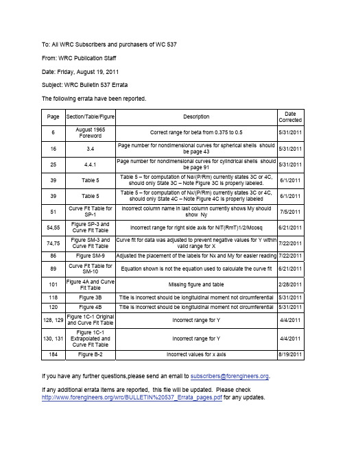
To: All WRC Subscribers and purchasers of WC 537 From: WRC Publication Staff Date: Friday, August 19, 2011 Subject: WRC Bulletin 537 Errata The following errata have been reported.Page Section/Table/Figure DescriptionDate Corrected 6August 1965 ForewordCorrect range for beta from 0.375 to 0.55/31/201116 3.4 Page number for nondimensional curves for spherical shells shouldbe page 43 5/31/201125 4.4.1 Page number for nondimensional curves for cylindrical shells shouldbe page 91 5/31/201139 Table 5Table 5 – for computation of Nø/(P/Rm) currently states 3C or 4C,should only State 3C – Note Figure 3C is properly labeled. 6/1/2011 39 Table 5Table 5 – for computation of Nx/(P/Rm) currently states 3C or 4C,should only State 4C – Note Figure 4C is properly labeled 6/1/2011 51 Curve Fit Table forSP-1 Incorrect column name in last column currently shows My shouldshow Ny7/5/2011 54,55 Figure SP-3 and Curve Fit TableIncorrect range for right side axis for NiT(RmT)1/2/Mcosq6/21/201174,75 Figure SM-3 and Curve Fit Table Curve fit for data was adjusted to prevent negative values for Y withinvalid range for X 7/22/201186 Figure SM-9 Adjusted the placement of the labels for Nx and My for easier reading 7/22/201189 Curve Fit Table forSM-10 Equation shown is not the equation used to calculate the curve fit6/21/2011101 Figure 4A and CurveFit TableMissing figure and table2/28/2011118 Figure 3B Title is incorrect should be longituidinal moment not circumferential 5/31/2011120 Figure 4B Title is incorrect should be longituidinal moment not circumferential 5/31/2011128, 129Figure 1C-1 Original and Curve Fit Table Incorrect range for Y4/4/2011130, 131 Figure 1C-1 Extrapolated and Curve Fit Table Incorrect range for Y 4/4/2011 184Figure B-2Incorrect values for x axis8/19/2011If you have any further questions,please send an email to subscribers@ . If any additional errata items are reported, this file will be updated. Please check/wrc/BULLETIN%20537_Errata_pages.pdf for any updates.The Welding Research Council, Inc.WRC 537Local Stresses in Spherical and Cylindrical Shells Due To External Loading5FOREWORDTo WRC Bulletin 107, March 1979 Update of August 1965 Original VersionWelding Research Council Bulletin No. 107 has been one of the most widely used bulletins ever published by WRC. The original bulletin was published in August 1965. Since that time, a revised printing was issued in December 1968; a second revised printing was issued in July 1970; a third revised printing was released in April 1972; and a June 1977 reprint of the third revised printing was issued. As sometimes happens with publications of this type, some errors were detected and then corrected in subsequent revised printings.In this March 1979 Revision of Bulletin 107, there are some additional revisions and clarifications. The formulations for calculation of the combined stress intensity, S, in Tables 2, 3, and 5 have been clarified. Changes in labels in Figures 1C-1, 2C-1, 3C , and 4C have been made and the calculated stresses for Model "R" in Table A-3 and Model "C-l" in Table A-4 have been revised accordingly. The background for the change in labels is given in a footnote on p. 66.Present plans call for a review and possible extension of curves to parameters which will cover the majority of openings in nuclear containment vessels and large storage tanks. Plans are to extend /R T from 300 to 600 and to extend /d D range from 0.003 to 0.10 for the new /R T range, review available test data to establish limits of applicability, and develop some guidance for pad reinforcements.Long range plans are to review shell theory in general, and Bijlaard's method in particular. The goal is to extend the /R T up to 1200 for a /d D up to 0.1. This will include large deflection theory and other nonlinear effects. In addition, available computer programs will be studied in hope of developing one which will be an appropriate supplement to Bijlaard's method. Finally, a review will be made of limit loads related to large /R T and small /d D .J.R, Farr, Chairman PVRC Design DivisionThe Welding Research Council, Inc.WRC 5376Local Stresses in Spherical and Cylindrical Shells Due To External LoadingFOREWORDTo WRC Bulletin 107, August 1965 Original VersionSeveral years ago, the Pressure Vessel Research Committee sponsored an analytical and experimental research program aimed at providing methods of determining the stresses in pressure vessel nozzle connections subjected to various forms of external loading. The analytical portion of this work was accomplished by Prof. P. P. Bijlaard of Cornell University, and was reported in References 1 to 8 inclusive. Development of the theoretical solutions involved a number of simplifying assumptions, including the use of shallow shell theory for spherical vessels and flexible loading surfaces for cylindrical vessels. These circumstances limited the potential usefulness of the results to /i i d D , ratios of perhaps 0.33 in the case of spherical shells and 0.25 in the case of cylindrical shells. Since no data were available for the larger diameter ratios, Prof. Bijlaard later supplied data, at the urging of the design engineers, for the values of 0.375β= and0.50 (/i i d D , ratios approaching 0.60) for cylindrical shells, as listed on page 12 of Reference 10.In so doing, Prof. Bijlaard included a specific warning concerning the possible limitations of these data, as follows: "The values for these large loading surfaces were computed on request of several companies. It should be remembered, however, that they actually apply to flexible loading surfaces and, for radial load, to the center of the loading surface. It should be understood that using these values for the edge of the attachment, as was recommended for small loading surfaces, may be unconservative.''Following completion of the theoretical work, experimental work was undertaken in an effort to verify the theory, the results of which were published in References 17 and 18. Whereas this work seemingly provided reasonable verification of the theory, it was limited to relatively small /i i d D ratios-0.10 in the case of spherical shells and 0.126 in the case of cylindrical shells. Since virtually no data, either analytical or experimental, were available covering the larger diameter ratios, the Bureau of Ships sponsored a limited investigation of this problem in spheres, aimed at a particular design problem, and the Pressure Vessel Research Committee undertook a somewhat similar investigation in cylinders. Results of this work have recently become available emphasizing the limitations in Bijlaard 's data on cylindrical shells, particularly as it applies to thin shells over the "extended range " (page 12 of Reference 10).Incident to the use of Bijlaard's data for design purposes, it has become apparent that design engineers sometimes have difficulty in interpreting or properly applying this work. As a result of such experience, PVRC has felt it desirable that all of Bijlaard's work be summarized in convenient, "cook-book" form to facilitate its use by design engineers. However, before this document could be issued, the above mentioned limitations became apparent, presenting an unfortunate dilemma, viz., the test data indicate that the calculated data are partially inadequate, but the exact nature and magnitude of the error is not known, nor is any better analytical treatment of the problem available (for cylinders).Under these circumstances, it was decided that the best course was to proceed with issuing the "cook-book," extending Bijlaard's curves as best we can on the basis of available test data. This decision was based on the premise that all of the proposed changes would be toward the conservative (or "safe") side and that design engineers would continue to use Bijlaard 's extended range data unless some alternative were offered. The following paper is therefore presented in the hope that it will facilitate the use of Bijlaard's work by design engineers. Every effort has been made to point out any known limitations in the work and to explain the exact nature of the changes which have been made to Bijlaard's original curves and data; however, users are warned that the resulting work is not necessarily adequate for all cases. It is the hope of the Subcommittee that additional theoretical work can be undertaken to provide more adequate data on various phases of this problem.F. S.G. Williams, ChairmanPVRC Subcommittee on Reinforced Openings and External LoadingsThe Welding Research Council, Inc.WRC 537Local Stresses in Spherical and Cylindrical Shells Due To External Loading153.3.2 Stresses Resulting From Overturning Moment,M3.3.2.1Radial Stresses (x σ)a) STEP 1. Using the applicable values of *,,U and ρϒ, read off the dimensionless membrane force()/xN M from the applicable curve which will be found in one of the following figures:Figure SR-3 or SM-1 to SM-10, inclusive.b) STEP 2. By the same procedure used in STEP 1 above, read off the value of dimensionless bendingmoment ()/M M from the applicable curve. This value will be found in the same figureused in STEP 1.c) STEP 3. Using the applicable values of ,,m M R and T , calculate the radial membrane stress()/x N Tby:x N T ⎞=⎝(12) d) STEP 4. By a procedure similar to that used in STEP 3, calculate the radial bending stress()26xMT, thus:26x M T ⎞=⎝ (13) e) STEP 5. Combine the radial membrane and bending stresses by use of the general stress equation(paragraph 2) together with the proper choice of sign (see Table 1); i.e.,26x x x nb N MK K T Tσ=± (14) 3.3.2.2Tangential Stress (y σ)Follow the five steps outlined in 3.3.2.1, using the same figure to obtain ()/y N Mand()/MM used to obtain ()/x N T P and ()/x M P .It follows that:yN T ⎛⎞=⎝⎠(15) 26yM T ⎛⎞=⎝⎠ (16) 26y yy nbN M K K T Tσ=± (17)The Welding Research Council, Inc.WRC 53716Local Stresses in Spherical and Cylindrical Shells Due To External Loading3.3.3Stresses Resulting From Torsional Moment, T MIn the case of a round attachment (such as a pipe), torsional moment is assumed to induce pure shear stresses, so that shear stress ()τ in the shell at the attachment-to-shell juncture is given by:202Tyx xy M r Tττπ==(18) If only shear stresses are being considered, it is to be noted that the equivalent stress intensity is twice the above calculated shear stress.In the case of rectangular attachments, torsional moment produces a complex stress field in the shell. Acceptable methods of analyzing this situation are not available at this time. If the designer has reason for concern, the problem should be resolved by testing in accordance with established code procedures. 3.3.4 Stresses Resulting From Shear Load, V Bijlaard has proposed 14 that shear force()V can be assumed transmitted to the shell entirely bymembrane shear force. Therefore, stresses in the shell at the attachment-to-shell juncture can be approximated as follows:3.3.4.1 Round Attachment0sin xy V(refer to Figure 1)r T τθπ=(19)3.3.4.2 Square Attachment1(90270)4xy V at and c Tτθ==°° (20)3.3.5 Stresses Resulting From Arbitrary LoadingIn the general case, all applied loads and moments must be resolved (at the attachment-shell interface) in the three principal directions; i.e., they must be resolved into components 1212,,,,,T P V V M M and M . If one then proceeds in the manner previously outlined, membrane, bending and shear stresses can be evaluated at eight distinct points in the shell at its juncture with the attachment. These eight points are shown in the sign convention chart, Table 1.The numerous stress components can be readily accounted for, if a scheme similar to that shown in Table 2 and 3 is adopted. In using this scheme, it is to be noted that the Maximum Shear Theory has been used to determine equivalent stress intensities. Also, it is to be noted that evaluation of stresses resulting from internal pressure has been omitted.Test work conducted by PVRC has shown that stresses attenuate rapidly at points removed from the attachment-to-shell juncture, the maximum stress frequently being located at the juncture.* However, in the general case of arbitrary loading, one has no assurance that the absolute maximum stress intensity in the shell will be located at one of the eight points considered in the above discussion.3.4 List Of Nondimensional Curves For Spherical ShellsThe nondimensional curves for solid and hollow attachments in spherical shells is shown on page 43 .*Under certain conditions stresses may be higher in the nozzle wall than they are in the vessel wall. This possibility is most likely if the nozzle opening in not reinforced or if the reinforcement is placed on the vessel wall and not on the nozzle.The Welding Research Council, Inc.WRC 537Local Stresses in Spherical and Cylindrical Shells Due To External Loading254.3.5.2 Rectangular Attachment14cx V c Tφτ=(50) 24Lx V c Tφτ=(51) 4.3.6 Stresses Resulting From Arbitrary LoadingIn the general case, all applied loads and moments must be resolved (at the attachment-to-shell interface) in the three principal directions; i.e., they must be resolved into components ,,,,,c L c L T P V V M M and M . If one then proceeds in the manner previously outlined (e.g., paragraph 4.3.1.1), membrane, bending and shear stresses can be evaluated at eight points in the shell at its juncture with the attachment. These eight points are shown in the sign convention chart, Table 4.4.4 Nondimensional Curves For Cylindrical ShellsThe nondimensional curves which follow constitute, in general, a replot of Bijlaard's data to a semilog scale in order that certain portions of the curves can be read with greater facility. Those portions of the curves which are taken directly from Bijlaard's work are shown as solid curves; those portions of the curves which have been modified on the basis of recent experimental data, as discussed in Appendix A, are shown as dotted curves.In the case of longitudinal moment loading and axial loading (thrust), two sets of curves are shown for the bending components of stress-one set applying to the longitudinal axis, and the other applying to an area of maximum stress off the axes of symmetry (longitudinal moment), or to the transverse axis (thrust). In the latter case, a portion of the original curves has been deleted in order to emphasize that the curves should not be used beyond the limits indicated. This was done because the available data indicated that the "outer limits" of the curves were appreciably unconservative, with no feasible manner to "correct" them (as explained in Appendix A).In the case of longitudinal moment , the exact location, of the maximum stress cannot be defined with certainty, but Figure A-14 will provide an estimate of its location (considering that the location of maximum stress under internal pressure and longitudinal moment was essentially the same on IIT model "C-1," as shown on Figures A-2 and A-3). It should also be noted that, to the best of our knowledge, the curves for "maximum stresses off the axes of symmetry" (Figures 1B-1 and 2B-1) would apply only to the case of a round, flexible nozzle connection; it is conceivable that a similar effect might apply to a rigid square or rectangular attachment, for which the shell at the outer edges of the attachment might take a greater part of the load than that portion of the shell adjacent to the longitudinal centerline. However, we know of no direct evidence to support such an assumption.4.4.1 List Of Nondimensional Curves For Cylindrical ShellsThe list of nondimensional curves for cylindrical shells is shown on page 91.4.5 Limits On ApplicationWhere relatively large attachments are considered, or when situations are encountered that deviate considerably from the idealized cases presented herein, the designer should refer to paragraph A.3 in Appendix A and to the original references to ascertain the limitations of applicability for the procedure used. However, there are a few generalizations that can safely be made regarding vessel and attachment geometry.The Welding Research Council, Inc.WRC 53726Local Stresses in Spherical and Cylindrical Shells Due To External Loading4.5.1 External Radial LoadStresses are affected very little by the ratio of shell length to shell radius ()/m l R . Therefore, no restriction is made on the point of load application except in very extreme cases. The curves included in this report are for an /m l R ratio of 8, which is sufficient for most practical applications. On the basis of data presented in Bibliographical Reference 2, results based on an /m l R ratio of 8 will be slightly conservative for lesser values of /m l R ratio and unconservative for greater values of /m l R ratio. However, the error involved does not exceed approximately 10% of all /m l R values greater than 3, which should be sufficiently accurate for most calculations. Since for lesser values of /m l R , the results are conservative, no restriction will ordinarily be necessary on /m l R ratio or the point of load application. For extreme cases or for "off center" loading, one may make corrections by use of the curves presented on page 8 of Bibliographical Reference 2, if desired.Results are not considered applicable in cases where the length of the cylinder ()l is less than its radius()m R . This applies either to the case of an open ended cylinder or closed ended cylinder where thestiffness is appreciably modified from the case considered.4.5.2 External MomentResults are applicable in the case of longitudinally off center attachments (a more usual case) provided that the attachment is located at least half the shell radius ()0.5m R from the end of the cylinder.4.5.3 Attachment StressesThe foregoing procedure provides one with a tool to find stresses in the shell, but not in the attachment. Under certain conditions, stresses may be higher in the attachment than they are in the vessel. For example, in the case of a nozzle, it is likely that the stresses will be higher in the nozzle wall than they are in the vessel wall if the nozzle opening is unreinforced or if the reinforcement is placed on the vessel wall and not on the nozzle.5 ACKNOWLEDGMENTThe authors wish to acknowledge the significant contributions made by J. B. Mahoney of Applied Technology Associates Inc. and M. G. Dhawan of the Bureau of Ships during the preparation of this paper. In addition, the comments received during the review of this document by the members of the PVRC Subcommittee on Reinforced Openings and External Loadings are deeply appreciated.6 REFERENCES1. Bijlaard, P. P., "Stresses from local Loadings in Cylindrical Pressure Vessels," Trans. A.S.M.E., 77,805-816 (1955).2. Bijlaard, P. P., "Stresses from Radial Loads in Cylindrical Pressure Vessels," Welding Jnl., 33 (12),Research Supplement, 615-s to 623-s (1954).3. Bijlaard, P. P., "Stresses from Radial Loads and External Moments in Cylindrical Pressure Vessel,"Ibid., 34 (12). Research Supplement, 608-s to 617-s (1955).4. Bijlaard, P. P., "Computation of the Stresses from Local Loads in Spherical Pressure Vessels orPressure Vessel Heads," Welding Research Council Bulletin No. 34, (March 1957).5. Bijlaard, P. P., "Local Stresses in Spherical Shells from Radial or Moment Loadings," Welding Jnl., 36(5), Research Supplement, 240-s to 243-s (1957).6. Bijlaard, P. P., "Stresses in a Spherical Vessel from Radial Loads Acting on a Pipe," Welding ResearchCouncil Bulletin No. 49, 1-30 (April 1959).7. Bijlaard, P. P., "Stresses in a Spherical Vessel from External Moments Acting on a Pipe," Ibid., No. 49,31-62 (April 1959).The Welding Research Council, Inc.Table 5 Continued – Computation Sheet for Local Stresses in Cylindrical ShellsWRC 537Local Stresses in Spherical and Cylindrical Shells Due To External Loading 39The Welding Research Council, Inc.WRC 53740Local Stresses in Spherical and Cylindrical Shells Due To External LoadingTable 6 – Radial Load PTable 7 – Circumferential Moment c M12/ββγc K for θ c K for M φc xK for M c C for N φ c x C for N0.2515 1.09 1.31 1.84 0.31 0.4950 1.04 1.24 1.62 0.21 0.46 100 0.97 1.16 1.45 0.15 0.44 300 0.92 1.02 1.17 0.09 0.46 0.515 1.00 1.09 1.36 0.64 0.7550 0.98 1.08 1.31 0.57 0.75 100 0.94 1.04 1.26 0.51 0.76 300 0.95 0.99 1.13 0.39 0.77 215 (1.00) (1.20) (0.97) (1.7) (1.3)100 1.19 1.10 0.95 1.43 1.12 300 --- (1.00) (0.90) (1.3) (1.00) 415 (1.00) (1.47) (1.08) (1.75) (1.31)100 1.49 1.38 1.06 1.49 0.81 300 --- (1.27) (0.98) (1.36) (0.74)Note: The values in parenthesis determined by an approximate solution.C u r v e F i t C o e f f i c i e n t s f o r F i g u r e S P -1The Welding Research Council Inc.F i g u r e S P - 2 S t r e s s e s i n S p h e r i c a l S h e l l D u e t o a R a d i a l L o a d P o n N o z z l e C o n n e c t i o n0.01N xN yx (M A X )y (MA X )The Welding Research Council Inc.C u r v e F i t C o e f f i c i e n t s f o r F i g u r e S P -2The Welding Research Council Inc.F i g u r e S P -3 – S t r e s s e s i n S p h e r i c a l S h e l l D u e t o a R a d i a l L o a d P o n N o z z l e C o n n e c t i o nThe Welding Research Council Inc.C u r v e F i t C o e f f i c i e n t s f o r F i g u r e S P -3The Welding Research Council Inc.F i g u r e S P -4 – S t r e s s e s i n S p h e r i c a l S h e l l D u e t o a R a d i a l L o a d P o n N o z z l e C o n n e c t i o n0.01N xN yM x(M A X )The Welding Research Council Inc.C u r v e F i t C o e f f i c i e n t s f o r F i g u r e S M -2The Welding Research Council Inc.F i g u r eS M-3 – S t r e s s e s i n S p h e r i c a l S h e l l D u e t o O v e r t u r n i n g M o m e n tM o n a N o z z l e C o n n e c t i o nThe Welding Research Council Inc.r R TC u r v e F i t C o e f f i c i e n t s f o r F i g u r e S M -3The Welding Research Council Inc.F i g u r eS M-4 – S t r e s s e s i n S p h e r i c a l S h e l l D u e t o O v e r t u r n i n g M o m e n tM o n a N o z z l e C o n n e c t i o n0.010.10.1N xM yN y (M A X )M x (MA X )The Welding Research Council Inc.C u r v e F i t C o e f f i c i e n t s f o r F i g u r e S M -8The Welding Research Council Inc.F i g u r eS M-9 – S t r e s s e s i n S p h e r i c a l S h e l l D u e t o O v e r t u r n i n g M o m e n tM o n a N o z z l e C o n n e c t i o nThe Welding Research Council Inc.r R TC u r v e F i t C o e f f i c i e n t s f o r F i g u r e S M -10The Welding Research Council Inc.The Welding Research Council, Inc.THIS PAGE INTENTIONALLY LEFT BLANKC u r v e F i t C o e f f i c i e n t s f o r F i g u r e 3A – E x t r a p o l a t e dThe Welding Research Council Inc.F i g u r e 4A – M o m e n t()2/cmN MR φβ D u e t o a n E x t e r n a l C i r c u m f e r e n t i a l M o m e n t c M on a C i r c u l a r C y l i n d e r – O r i g i n a lThe Welding Research Council Inc.βC u r v e F i t C o e f f i c i e n t s f o r F i g u r e 4A – O r i g i n a lThe Welding Research Council Inc.i g u r e 1B – M o m e n t()/L m M M R φβ D u e t o a n E x t e r n a l L o n g i t u d i n a l M o m e n t LMo n a C i r c u l a r C y l i n d e r (S t r e s s o n t h e L o n g i t u d i n a l P l a n e o fS y m m e t r y ) – O r i g i n a lβThe Welding Research Council Inc.C u r v e F i t C o e f f i c i e n t s f o r F i g u r e 2B -1 – E x t r a p o l a t e dThe Welding Research Council Inc.F i g u r e 3B – M e m b r a n e F o r c e()2/LmN MR φβ D u e t o a n E x t e r n a l L o n g i t u d i n a l M o m en t LMo n a C i r c u l a r C y l i n d e r – O r i g i n a lβThe Welding Research Council Inc.C u r v e F i t C o e f f i c i e n t s f o r F i g u r e 1C – E x t r a p o l a t e dWRC Bulletin 537Local Stresses in Spherical and Cylindrical Shells Due To External Loading127The Welding Research Council Inc.F i g u r e 1C -1 – B e n d i n g M o m e n tx M PD u e t o a nE x t e r n a l R a d i a l L o a d P o n a C i r c u l a r C y l i n d e r (L o n g i t u d i n a l A x i s ) – O r i g i n a l WRC Bulletin 537128Local Stresses in Spherical and Cylindrical Shells Due To External LoadingThe Welding Research Council Inc.C u r v e F i t C o e f f i c i e n t s f o r F i g u r e 1C -1 – O r i g i n a lWRC Bulletin 537Local Stresses in Spherical and Cylindrical Shells Due To External Loading129The Welding Research Council Inc.F i g u r e 1C -1 – B e n d i n g M o m e n tx M PD u e t o a nE x t e r n a l R a d i a l L o a d P o n a C i r c u l a r C y l i n d e r (L o n g i t u d i n a l A x i s ) – E x t r a p o l a t e d 0.10.5WRC Bulletin 537130Local Stresses in Spherical and Cylindrical Shells Due To External LoadingThe Welding Research Council Inc.C u r v e F i t C o e f f i c i e n t s f o r F i g u r e 1C -1 – E x t r a p o l a t e dWRC Bulletin 537Local Stresses in Spherical and Cylindrical Shells Due To External Loading131The Welding Research Council Inc.F i g u r e 2C – B e n d i n g M o m e n tx M PD u e t o a nE x t e r n a l R a d i a l L o a d P o n a C i r c u l ar C y l i n d e r (T r a n s v e r s e A x i s ) – O r i g i n a l WRC Bulletin 537132Local Stresses in Spherical and Cylindrical Shells Due To External LoadingThe Welding Research Council Inc.The Welding Research Council, Inc.WRC 537Local Stresses in Spherical and Cylindrical Shells Due To External Loading183B.6 FiguresFigure B-1 – Stepped BarThe Welding Research Council, Inc.WRC 537184Local Stresses in Spherical and Cylindrical Shells Due To External Loading00.050.100.150.200.250.300.35Scale BScale A0.51.01.52.02.53.03.5S t r e s s C o n c e n t r a t i o n F a c t o r , KRatio of Fillet Radius to Shellor Nozzle Thickness (r/T, 2r/d n , or 2r/h)5.04.03.02.01.51.0Figure B-2 – Stress Concentration Factors for D d >>。

API Spec5L第44版的最新修订李雪成【期刊名称】《石油工业技术监督》【年(卷),期】2011(027)007【摘要】API Spec 5L 《管线管规范》第44版自2007年10月出版后,针对其中的错误和不足,美国石油学会相继于2009年1月发布了勘误(ERRATA,生效日期2009年8月1日),2009年2月发布了补遗1(ADDENDUM 1,生效日期2009年8月1日),2010年3月发布了补遗2 (ADDENDUM 2,生效日期2010年10月1日)[1].勘误和补遗是对标准内容的补充和完善,在发布并生效后,也同时成为标准的一部分,在标准适用的场合具有强制约束力.因而,无论是依据API Spec 5L标准进行采购的购方,还是按照API Spec 5L标准要求进行生产的制造厂,以及依据API Spec 5L标准进行监督检验的第三方,均需重视API Spec 5L标准的变化及相应变化可能带来的影响,以避免因标准理解差异而导致的产品质量争议和纠纷.【总页数】5页(P33-37)【作者】李雪成【作者单位】西安摩尔石油工程实验室(陕西西安710065)【正文语种】中文【相关文献】1.两极化刑事政策导向下的刑法修订 --简评2005年最新修订的台湾刑法典 [J], 冯卫国;肖月2.《API SPEC5L/ISO3183管线钢管》标准最新进展 [J], 许晓锋;李为卫;秦长毅;赵晓姣3.API Spec5L(44版)关于材料及试验的变化 [J], 王德林;同建辉;孙宏;崔明亮4.API Spec5L第46版标准培训班即将开班 [J], ;5.第4版API682标准带来了什么?美国右油协会修订了机械密封和供应系统API682标准 [J],因版权原因,仅展示原文概要,查看原文内容请购买。

HTTP请求的错误码大全//ACTION_ERROR 错误定义#define RS_OK 0#define RS_ERROR -1#define RS_HTTP_COMP_SERVER_EMPTY 2000 //HTTP返回字节数为0,服务器确实没有一个文件和目录.#define RS_HTTP_RETURN_NULL 1000//HTTP返回字节数为0 #define RS_HTTP_RETURNBYTE_ERROR 1001//HTTP返回字节与读出字节不相同#define RS_NOCAPTCHA 1002//不需要验证码#define RS_RELOGIN 1003//重新登陆#define RS_PASSWORDERROR 1004//用户名密码错误#define RS_LOGINERROR 1005//登陆失败#define RS_INTERNETDISK_NOTENOUGH 1006//网盘空间不足#define RS_HTTP_READFILE_ERR 1007#define RS_HTTP_MD5_NOTMATCH 1008#define RS_DOWNLOAD_MOVEFILE_ERROR 1009//下载文件后,移动文件失败#define RS_HTTP_SIZE_NOTMATCH 1011//文件长度不同#define RS_JsonOverflowException 2001#define RS_JsonNullPointerException 2002#define RS_JsonInvalidateIndexException 2003#define RS_JsonInvalidateParamException 2004#define RS_JsonUnsupportException 2005#define RS_JsonUnimplementException 2006#define RS_JsonWrongFormatException 2007#define RS_JsonMemberNotFoundException 2008#define RS_JsonException 2009#define RS_NONONCE 3001//下载挑战值失败#define RS_INPUT_NULL 3002//输入参数为空#define RS_OPENURLERROR 4001//打开网络连接失败#define RS_GETMSGURL 4002//获取心跳包URL失败#define RS_MSGCOMEBACK 4003//自己消息回调//#define RS_DISK_NOTENOUGH 4004//磁盘不足#define RS_DISK_FULL 4005//磁盘已经满了#define RS_UPLOAD_FILE_NOTEXIST 4006//上传的文件不存在,或者上传的为目录#define RS_UPLOAD_FILE_LATER 4007 //过一会儿再上传#define RS_UPLOAD_FILE_TOO_BIG 4008 //文件超大#define RS_UNKONWN_UPLOAD 4009//无法识别上传命令#define RS_TIMEOUT 4010#define RS_PARENT_PATH_NOT_EXIST 4011#define RS_EXIST_FILE 4012#define RS_HTTP_REGETCLIENTID 401312001 ERROR_INTERNET_OUT_OF_HANDLESNo more handles could be generated at this time.12002 ERROR_INTERNET_TIMEOUTThe request has timed out.12003 ERROR_INTERNET_EXTENDED_ERRORAn extended error was returned from the server. This istypically a string or buffer containing a verbose error message. Call InternetGetLastResponseInfo to retrieve the error text.12004 ERROR_INTERNET_INTERNAL_ERRORAn internal error has occurred.12005 ERROR_INTERNET_INVALID_URLThe URL is invalid.12006 ERROR_INTERNET_UNRECOGNIZED_SCHEME The URL scheme could not be recognized or is not supported.12007 ERROR_INTERNET_NAME_NOT_RESOLVEDThe server name could not be resolved.12008 ERROR_INTERNET_PROTOCOL_NOT_FOUNDThe requested protocol could not be located.12009 ERROR_INTERNET_INVALID_OPTIONA request to InternetQueryOption or InternetSetOption specified an invalid option value.12010 ERROR_INTERNET_BAD_OPTION_LENGTHThe length of an option supplied to InternetQueryOption or InternetSetOption is incorrect for the type of option specified.12011 ERROR_INTERNET_OPTION_NOT_SETTABLEThe request option cannot be set, only queried.12012 ERROR_INTERNET_SHUTDOWNThe Win32 Internet function support is being shut down or unloaded.12013 ERROR_INTERNET_INCORRECT_USER_NAME The request to connect and log on to an FTP server could not be completed because the supplied user name is incorrect.12014 ERROR_INTERNET_INCORRECT_PASSWORD The request to connect and log on to an FTP server could not be completed because the supplied password is incorrect.12015 ERROR_INTERNET_LOGIN_FAILUREThe request to connect to and log on to an FTP server failed.12016 ERROR_INTERNET_INVALID_OPERATIONThe requested operation is invalid.12017 ERROR_INTERNET_OPERATION_CANCELLED The operation was canceled, usually because the handle on which the request was operating was closed before the operation completed.12018 ERROR_INTERNET_INCORRECT_HANDLE_TYPE The type of handle supplied is incorrect for this operation.12019 ERROR_INTERNET_INCORRECT_HANDLE_STATEThe requested operation cannot be carried out because the handle supplied is not in the correct state.12020 ERROR_INTERNET_NOT_PROXY_REQUESTThe request cannot be made via a proxy.12021 ERROR_INTERNET_REGISTRY_VALUE_NOT_FOUN DA required registry value could not be located.12022 ERROR_INTERNET_BAD_REGISTRY_PARAMETERA required registry value was located but is an incorrecttype or has an invalid value.12023 ERROR_INTERNET_NO_DIRECT_ACCESSDirect network access cannot be made at this time.12024 ERROR_INTERNET_NO_CONTEXTAn asynchronous request could not be made because a zero context value was supplied.12025 ERROR_INTERNET_NO_CALLBACKAn asynchronous request could not be made because acallback function has not been set.12026 ERROR_INTERNET_REQUEST_PENDINGThe required operation could not be completed because one or more requests are pending.12027 ERROR_INTERNET_INCORRECT_FORMATThe format of the request is invalid.12028 ERROR_INTERNET_ITEM_NOT_FOUNDThe requested item could not be located.12029 ERROR_INTERNET_CANNOT_CONNECTThe attempt to connect to the server failed.12030 ERROR_INTERNET_CONNECTION_ABORTED The connection with the server has been terminated.12031 ERROR_INTERNET_CONNECTION_RESETThe connection with the server has been reset.12032 ERROR_INTERNET_FORCE_RETRYCalls for the Win32 Internet function to redo the request.12033 ERROR_INTERNET_INVALID_PROXY_REQUEST The request to the proxy was invalid.12036 ERROR_INTERNET_HANDLE_EXISTSThe request failed because the handle already exists.12037 ERROR_INTERNET_SEC_CERT_DATE_INVALID SSL certificate date that was received from the server is bad. The certificate is expired.12038 ERROR_INTERNET_SEC_CERT_CN_INVALIDSSL certificate common name (host name field) is incorrect.For example, if you entered and the commonname on the certificate says .12039 ERROR_INTERNET_HTTP_TO_HTTPS_ON_REDIRThe application is moving from a non-SSL to an SSLconnection because of a redirect.12040 ERROR_INTERNET_HTTPS_TO_HTTP_ON_REDIRThe application is moving from an SSL to an non-SSLconnection because of a redirect.12041 ERROR_INTERNET_MIXED_SECURITYIndicates that the content is not entirely secure. Some ofthe content being viewed may have come from unsecured servers.12042 ERROR_INTERNET_CHG_POST_IS_NON_SECUREThe application is posting and attempting to changemultiple lines of text on a server that is not secure.12043 ERROR_INTERNET_POST_IS_NON_SECUREThe application is posting data to a server that is notsecure.12110 ERROR_FTP_TRANSFER_IN_PROGRESSThe requested operation cannot be made on the FTP session handle because an operation is already in progress.12111 ERROR_FTP_DROPPEDThe FTP operation was not completed because the session wasaborted.12130 ERROR_GOPHER_PROTOCOL_ERRORAn error was detected while parsing data returned from the gopher server.12131 ERROR_GOPHER_NOT_FILEThe request must be made for a file locator.12132 ERROR_GOPHER_DATA_ERRORAn error was detected while receiving data from the gopher server.12133 ERROR_GOPHER_END_OF_DATAThe end of the data has been reached.12134 ERROR_GOPHER_INVALID_LOCATORThe supplied locator is not valid.12135 ERROR_GOPHER_INCORRECT_LOCATOR_TYPEThe type of the locator is not correct for this operation.12136 ERROR_GOPHER_NOT_GOPHER_PLUSThe requested operation can only be made against a Gopher+server or with a locator that specifies a Gopher+operation.12137 ERROR_GOPHER_ATTRIBUTE_NOT_FOUNDThe requested attribute could not be located.12138 ERROR_GOPHER_UNKNOWN_LOCATORThe locator type is unknown.12150 ERROR_HTTP_HEADER_NOT_FOUNDThe requested header could not be located.12151 ERROR_HTTP_DOWNLEVEL_SERVERThe server did not return any headers.12152 ERROR_HTTP_INVALID_SERVER_RESPONSEThe server response could not be parsed.12153 ERROR_HTTP_INVALID_HEADERThe supplied header is invalid.12154 ERROR_HTTP_INVALID_QUERY_REQUESTThe request made to HttpQueryInfo is invalid.12155 ERROR_HTTP_HEADER_ALREADY_EXISTSThe header could not be added because it already exists.12156 ERROR_HTTP_REDIRECT_FAILEDThe redirection failed because either the scheme changed (for example, HTTP to FTP) or all attempts made to redirect failed (default is five attempts).。

网络错误代码大全WEB服务器错误代码大全,web开发过程中经常碰到的问题http错误代码 http错误404 http错误403 http错误405·400 - 错误的请求。
·401 - 访问被拒绝。
IIS 定义了许多不同的 401 错误,它们指明更为具体的错误原因。
这些具体的错误代码在浏览器中显示,但不在IIS 日志中显示:·401.1 - 登录失败。
·401.2 - 服务器配置导致登录失败。
·401.3 - 由于 ACL 对资源的限制而未获得授权。
·401.4 - 筛选器授权失败。
·401.5 - ISAPI/CGI 应用程序授权失败。
·401.7 –访问被 Web 服务器上的 URL 授权策略拒绝。
这个错误代码为 IIS 6.0 所专用。
·403 - 禁止访问:IIS 定义了许多不同的 403 错误,它们指明更为具体的错误原因:·403.1 - 执行访问被禁止。
·403.2 - 读访问被禁止。
·403.3 - 写访问被禁止。
·403.4 - 要求 SSL。
·403.5 - 要求 SSL 128。
·403.6 - IP 地址被拒绝。
·403.7 - 要求客户端证书。
·403.8 - 站点访问被拒绝。
·403.9 - 用户数过多。
·403.10 - 配置无效。
·403.11 - 密码更改。
·403.12 - 拒绝访问映射表。
·403.13 - 客户端证书被吊销。
·403.14 - 拒绝目录列表。
·403.15 - 超出客户端访问许可。
·403.16 - 客户端证书不受信任或无效。
·403.17 - 客户端证书已过期或尚未生效。
·403.18 - 在当前的应用程序池中不能执行所请求的 URL。

erratas翻译Erratas 是指书籍、文件或印刷品中的错误或纰漏。
下面是关于erratas 的翻译和一些用法和中英文对照例句:翻译:- 英文:erratas- 中文:勘误表用法:1. 提交勘误表:- 英文:Submit an errata.- 中文:提交勘误表。
2. 修正错误:- 英文:Correct the erratas.- 中文:纠正勘误表中的错误。
3. 更新版本:- 英文:Publish an updated version with the erratas.- 中文:发布一份包含勘误表的更新版。
4. 修订出版物:- 英文:Revise the publication to address the erratas.- 中文:修订出版物以处理勘误表中的错误。
中英文对照例句:1. The author has provided an errata for the book, addressing the errors found in the previous edition.(作者为这本书提供了一份勘误表,解决了上一版中发现的错误。
)2. The publisher released an updated version of the textbook, including all the erratas that were reported by readers.(出版商发布了一份更新版教科书,其中包含了读者报告的所有勘误表。
)3. The author was quick to acknowledge the erratas in the research paper and issued a formal apology.(作者迅速承认了研究论文中的勘误表,并发表了正式道歉。
)4. The editorial team carefully reviewed the manuscript and identified several erratas that needed to be corrected before publication.(编辑团队仔细审查了手稿,并确定了几处在出版之前需要纠正的勘误表。

errorcode错误代码含义查询error code(错误代码)=0是操作成功完成。
error code(错误代码)=1是功能错误。
error code(错误代码)=2是系统找不到指定的⽂件。
error code(错误代码)=3是系统找不到指定的路径。
error code(错误代码)=4是系统⽆法打开⽂件。
error code(错误代码)=5是拒绝访问。
error code(错误代码)=6是句柄⽆效。
error code(错误代码)=7是存储控制块被损坏。
error code(错误代码)=8是存储空间不⾜,⽆法处理此命令。
error code(错误代码)=9是存储控制块地址⽆效。
error code(错误代码)=10是环境错误。
error code(错误代码)=11是试图加载格式错误的程序。
error code(错误代码)=12是访问码⽆效。
error code(错误代码)=13是数据⽆效。
error code(错误代码)=14是存储器不⾜,⽆法完成此操作。
error code(错误代码)=15是系统找不到指定的驱动器。
error code(错误代码)=16是⽆法删除⽬录。
error code(错误代码)=17是系统⽆法将⽂件移到不同的驱动器。
error code(错误代码)=18是没有更多⽂件。
error code(错误代码)=19是介质受写⼊保护。
error code(错误代码)=20是系统找不到指定的设备。
error code(错误代码)=21是设备未就绪。
error code(错误代码)=22是设备不识别此命令。
error code(错误代码)=23是数据错误(循环冗余检查)。
error code(错误代码)=24是程序发出命令,但命令长度不正确。
error code(错误代码)=25是驱动器⽆法找出磁盘上特定区域或磁道的位置。
error code(错误代码)=26是⽆法访问指定的磁盘或软盘。
−−−ErrataIntermediate MicroeconomicsHal VarianOctober 14, 1999Errata in Fifth EditionPrinting 1p310. Corrected footnote wording to say that all four auction forms yield the same allo- cation and the same expected price, and add reference to Paul Klemperer’s survey.p311, line 10. Changed wording to say “an optimal strategy.”p311, line 20. Removed “strategically.”p612. Removed reference to “Figure” (which wasn’t included).p613. Changed α and β to a and b on entire page.Errata Remaining in Fourth Editionp19. A question got dropped, making question 7 unintelligible. Should add the question back in. (Pablo Florian)p. 215, figure 12.1 The “Choice” point on the horizontal axis is labelled $35, 000 γK K. It should be $25, 000 γK + K (the post-accident wealth, minus the premium paid, plus the insurance payment received).p. 241. “The Standard & Poor’s index is based on the average performance of 500 stocks traded on the New York Stock Exchange.” Not true! Many stocks other than NYSE stocks are in S&P500.p. 506, “According to Walras’ law it must also be true that ... ” In the following equation, th e p1and p2m u ltiplying t he excess demands should b e p∗1and p∗2.Printing 6337 Figure 19.1 the horizontal axis should be labeled x1, not x429, 14 up. x0 should be x m.1 1Printing 5Chapter 230, Figure 2.6. Needs A and B labels under figure.Chapter 7122, Figure 7.3. The line to the right of Z should be horizontal. (John Weymark) Chapter 12227, problem 2c. This is only an affine transformation for fixed π1 and the question doesn’t specify that. Probably should change the question to avoid confusion. (Marcelo Clerici- Arias)B AChapter 28 485, shift ω1 to left about .25 inch, and shift ω2 up by the same.Printing 4Chapter Prefacexxi, Profit Maximization chapter is omitted in flowchart by mistake.Chapter 230, Figure 2.6. Should draw figure to scale. Also, should have number.Chapter 346, should say “gives a weight of t to the x-bundle and 1 − t to the y-bundle.”51, 4 lines from start of section. Omit “at −1”.Chapter 12220, 9 up. 10 should be 15. (S-Maus)226, 2 up. Figure 12.2 should be 12.1 (S-Maus)Printing 4430, right before quote: “eighteenth” should be “nineteenth”.431, line 5. “eighteenth” should be “nineteenth.”489, fragment missing at top of page: “A senior director of marketing for a major U.S. airline described a case in which Northwest lowered fares on night flights from Minneapolis to various...”Printing 3Chapter 16285, 10 and 14 down. pp should be dp . (S-Maus) FIXED290, 6 down. it should be bt . (S-Maus)Chapter 19336, line 1. “equations” should be “expressions” (S -Maus) FIXEDChapter 20357, 3 lines below figure. “three” should be “four”. (S -Maus) FIXEDChapter 21371, figure caption. Should say “producer’s surplus”. (S -Maus) FIXEDChapter 22392, paragraph 4. say “industry with entry legally restricted.” (S -Maus)Chapter 25440, axis label: should say “factor” rather than “labor”. (S-Maus)445, (answer to question 2 on A23). Say “we would presumably see unemployment.” (S-Maus)Chapter 32576, line 10. Should be p −πγ(p −c). (S-Maus)Printing 2Chapter 230, Figure 2.6. Label is missing.Chapter 583, Table 5.1. Numbers in utility column should be (57., 33.9, 47.9, 67.8, 95.8, 80.6, 161.). (Ernest Lucas)84, middle of page. “... better off than he was in year 2 but worse off than he was in year 3.”Chapter 15245, Figure 14.1. Label on wrong side of page.Chapter 16285.line 10: pp should be dp. line 14: pp should be dp. line 20: DB should be bc. (Stefano Chinellato)286.line 4: CZ should be bc. (Stefano Chinellato)Chapter 21p. 371, Figure 21.5. Figure explanation should say producer surplus, not consumer surplus. Printing 1Chapter 27474. Game matrix should be white, not blue. (Hal Varian)Chapter 32568, line 9. Should say “... the expected cost of the crime to the criminal, π(e)F , is independent ... ” (Peter Huang)573, last word on page. Should be “victim.” (Peter Huang)Chapter AppendixA2. Figure should be drawn to scale.。
October 2013DocID022183 Rev 51/37STM32F40x and STM32F41xErrata sheetSTM32F405/407xx and STM32F415/417xxdevice limitationsSilicon identificationThis errata sheet applies to the revisions ‘A’, ‘Z’ and ‘1’ of STMicroelectronicsSTM32F405xx/STM32F407xx and STM32F415xx/STM32F417xx microcontroller families. In this document, they will be referred to as STM32F40x and STM32F41x, respectively, unless otherwise specified.The STM32F40x and STM32F41x families feature an ARM ® 32-bit Cortex™-M4 core with FPU, for which an errata notice is also available (see Section 1 for details).The full list of part numbers is shown in Table 2. The products are identifiable as shown in Table 1:•by the revision code marked below the order code on the device package •by the last three digits of the Internal order code printed on the box labelTable 1. Device identification (1)1.The REV_ID bits in the DBGMCU_IDCODE register show the revision code of the device (see theSTM32F40x and STM32F41x reference manual for details on how to find the revision code).Order codeRevision code marked on device (2)2.Refer to Appendix A: Revision code on device marking for details on how to identify the revision code andthe date code on the different packages.STM32F405xx, STM32F407xx ‘A’, ‘Z’, ‘1’STM32F415xx, STM32F417xxTable 2. Device summaryReference Part numberSTM32F405xx STM32F405OG, STM32F405OE, STM32F405RG, STM32F405VG, STM32F405ZGSTM32F407xx STM32F407IG, STM32F407VG, STM32F407ZG,STM32F407ZE, STM32F407IE, STM32F407VESTM32F415xx STM32F415OG, STM32F415RG, STM32F415VG, STM32F415ZG STM32F417xxSTM32F417VG, STM32F417IG, STM32F417ZG, STM32F417VE, STM32F417ZE, STM32F417IEContents STM32F40x and STM32F41xContents1ARM 32-bit Cortex-M4 with FPU limitations . . . . . . . . . . . . . . . . . . . . . . 71.1Cortex-M4 interrupted loads to stack pointer can causeerroneous behavior . . . . . . . . . . . . . . . . . . . . . . . . . . . . . . . . . . . . . . . . . . 72STM32F40x and STM32F41x silicon limitations . . . . . . . . . . . . . . . . . . . 82.1System limitations . . . . . . . . . . . . . . . . . . . . . . . . . . . . . . . . . . . . . . . . . . 102.1.1ART Accelerator prefetch queue instruction is not supported . . . . . . . . 102.1.2MCU device ID is incorrect . . . . . . . . . . . . . . . . . . . . . . . . . . . . . . . . . . 112.1.3Debugging Stop mode and system tick timer . . . . . . . . . . . . . . . . . . . . 112.1.4Debugging Stop mode with WFE entry . . . . . . . . . . . . . . . . . . . . . . . . . 112.1.5Wakeup sequence from Standby mode when using more thanone wakeup source . . . . . . . . . . . . . . . . . . . . . . . . . . . . . . . . . . . . . . . . 122.1.6Full JTAG configuration without NJTRST pin cannot be used . . . . . . . . 122.1.7PDR_ON pin not available on LQFP100 packagefor revision Z devices . . . . . . . . . . . . . . . . . . . . . . . . . . . . . . . . . . . . . . . 122.1.8Incorrect BOR option byte when consecutively programmingBOR option byte . . . . . . . . . . . . . . . . . . . . . . . . . . . . . . . . . . . . . . . . . . 132.1.9Configuration of PH10 and PI10 as external interrupts is erroneous . . . 132.1.10DMA2 data corruption when managing AHB and APB peripherals in aconcurrent way . . . . . . . . . . . . . . . . . . . . . . . . . . . . . . . . . . . . . . . . . . . 132.1.11Slowing down APB clock during a DMA transfer . . . . . . . . . . . . . . . . . . 142.1.12MPU attribute to RTC and IWDG registers could be managedincorrectly . . . . . . . . . . . . . . . . . . . . . . . . . . . . . . . . . . . . . . . . . . . . . . . 142.1.13Delay after an RCC peripheral clock enabling . . . . . . . . . . . . . . . . . . . . 142.1.14Battery charge monitoring lower than 2.4Volts . . . . . . . . . . . . . . . . . . . 152.1.15Internal noise impacting the ADC accuracy . . . . . . . . . . . . . . . . . . . . . . 152.2IWDG peripheral limitation . . . . . . . . . . . . . . . . . . . . . . . . . . . . . . . . . . . . 152.2.1RVU and PVU flags are not reset in STOP mode . . . . . . . . . . . . . . . . . 152.3I2C peripheral limitations . . . . . . . . . . . . . . . . . . . . . . . . . . . . . . . . . . . . . 162.3.1SMBus standard not fully supported . . . . . . . . . . . . . . . . . . . . . . . . . . . 162.3.2Start cannot be generated after a misplaced Stop . . . . . . . . . . . . . . . . . 162.3.3Mismatch on the “Setup time for a repeated Start condition” timingparameter . . . . . . . . . . . . . . . . . . . . . . . . . . . . . . . . . . . . . . . . . . . . . . . 162.3.4Data valid time (t VD;DAT) violated without the OVR flag being set . . . . . 172.3.5Both SDA and SCL maximum rise time (t r) violated when VDD_I2C bushigher than ((VDD+0.3) / 0.7)V . . . . . . . . . . . . . . . . . . . . . . . . . . . . . . . 18 2/37DocID022183 Rev 5STM32F40x and STM32F41x Contents2.4I2S peripheral limitation . . . . . . . . . . . . . . . . . . . . . . . . . . . . . . . . . . . . . . 182.4.1In I2S slave mode, WS level must be set by the external masterwhen enabling the I2S . . . . . . . . . . . . . . . . . . . . . . . . . . . . . . . . . . . . . . 182.4.2I2S2 in full-duplex mode may not work properly when SCK andWS signals are mapped on PI1 and PI0 respectively . . . . . . . . . . . . . . 192.5USART peripheral limitations . . . . . . . . . . . . . . . . . . . . . . . . . . . . . . . . . . 192.5.1Idle frame is not detected if receiver clock speed is deviated . . . . . . . . 192.5.2In full duplex mode, the Parity Error (PE) flag can be cleared bywriting to the data register . . . . . . . . . . . . . . . . . . . . . . . . . . . . . . . . . . . 192.5.3Parity Error (PE) flag is not set when receiving in Mute modeusing address mark detection . . . . . . . . . . . . . . . . . . . . . . . . . . . . . . . . 202.5.4Break frame is transmitted regardless of nCTS input line status . . . . . . 202.5.5nRTS signal abnormally driven low after a protocol violation . . . . . . . . 202.6OTG_FS peripheral limitations . . . . . . . . . . . . . . . . . . . . . . . . . . . . . . . . . 212.6.1Data in RxFIFO is overwritten when all channels are disabledsimultaneously . . . . . . . . . . . . . . . . . . . . . . . . . . . . . . . . . . . . . . . . . . . . 212.6.2OTG host blocks the receive channel when receiving IN packets and noTxFIFO is configured . . . . . . . . . . . . . . . . . . . . . . . . . . . . . . . . . . . . . . . 212.6.3Host channel-halted interrupt not generated when the channel isdisabled . . . . . . . . . . . . . . . . . . . . . . . . . . . . . . . . . . . . . . . . . . . . . . . . . 212.6.4Error in software-read OTG_FS_DCFG register values . . . . . . . . . . . . 222.7Ethernet peripheral limitations . . . . . . . . . . . . . . . . . . . . . . . . . . . . . . . . . 222.7.1Incorrect layer 3 (L3) checksum is inserted in transmitted IPv6 packetswithout TCP, UDP or ICMP payloads . . . . . . . . . . . . . . . . . . . . . . . . . . . 222.7.2The Ethernet MAC processes invalid extension headers in the receivedIPv6 frames . . . . . . . . . . . . . . . . . . . . . . . . . . . . . . . . . . . . . . . . . . . . . . 222.7.3MAC stuck in the Idle state on receiving the TxFIFO flush commandexactly 1 clock cycle after a transmission completes . . . . . . . . . . . . . . . 232.7.4Transmit frame data corruption . . . . . . . . . . . . . . . . . . . . . . . . . . . . . . . 232.7.5Successive write operations to the same register might not be fullytaken into account . . . . . . . . . . . . . . . . . . . . . . . . . . . . . . . . . . . . . . . . . 242.8FSMC peripheral limitation . . . . . . . . . . . . . . . . . . . . . . . . . . . . . . . . . . . . 262.8.1Dummy read cycles inserted when reading synchronous memories . . . 262.8.2FSMC synchronous mode and NWAIT signal disabled . . . . . . . . . . . . . 272.8.3FSMC NOR Flash/PSRAM controller asynchronous access on bank 2to 4 when bank 1 is in synchronous mode(CBURSTRW bit is set) . . . . . . . . . . . . . . . . . . . . . . . . . . . . . . . . . . . . . 272.9SDIO peripheral limitations . . . . . . . . . . . . . . . . . . . . . . . . . . . . . . . . . . . . 272.9.1SDIO HW flow control . . . . . . . . . . . . . . . . . . . . . . . . . . . . . . . . . . . . . . 272.9.2Wrong CCRCFAIL status after a response without CRC is received . . . 28DocID022183 Rev 53/37Contents STM32F40x and STM32F41x2.9.3SDIO clock divider BYPASS mode may not work properly . . . . . . . . . . 282.9.4Data corruption in SDIO clock dephasing (NEGEDGE) mode . . . . . . . . 282.9.5CE-ATA multiple write command and card busy signal management . . 282.9.6No underrun detection with wrong data transmission . . . . . . . . . . . . . . 292.10ADC peripheral limitations . . . . . . . . . . . . . . . . . . . . . . . . . . . . . . . . . . . . 292.10.1ADC sequencer modification during conversion . . . . . . . . . . . . . . . . . . 292.11DAC peripheral limitations . . . . . . . . . . . . . . . . . . . . . . . . . . . . . . . . . . . . 302.11.1DMA underrun flag management . . . . . . . . . . . . . . . . . . . . . . . . . . . . . . 302.11.2DMA request not automatically cleared by DMAEN=0 . . . . . . . . . . . . . 30 Appendix A Revision code on device marking . . . . . . . . . . . . . . . . . . . . . . . . . . 31 Revision history . . . . . . . . . . . . . . . . . . . . . . . . . . . . . . . . . . . . . . . . . . . . . . . . . . . . 354/37DocID022183 Rev 5STM32F40x and STM32F41x List of tables List of tablesTable 1.Device identification . . . . . . . . . . . . . . . . . . . . . . . . . . . . . . . . . . . . . . . . . . . . . . . . . . . . . . . 1 Table 2.Device summary. . . . . . . . . . . . . . . . . . . . . . . . . . . . . . . . . . . . . . . . . . . . . . . . . . . . . . . . . . 1 Table 3.Cortex-M4 core limitations and impact on microcontroller behavior. . . . . . . . . . . . . . . . . . . 7 Table 4.Summary of silicon limitations . . . . . . . . . . . . . . . . . . . . . . . . . . . . . . . . . . . . . . . . . . . . . . . 8 Table 5.Impacted registers and bits. . . . . . . . . . . . . . . . . . . . . . . . . . . . . . . . . . . . . . . . . . . . . . . . . 24 Table 6.Document revision history . . . . . . . . . . . . . . . . . . . . . . . . . . . . . . . . . . . . . . . . . . . . . . . . . 35DocID022183 Rev 55/37List of figures STM32F40x and STM32F41x List of figuresFigure 1.UFBGA176 top package view. . . . . . . . . . . . . . . . . . . . . . . . . . . . . . . . . . . . . . . . . . . . . . . 31 Figure 2.LQFP176 top package view . . . . . . . . . . . . . . . . . . . . . . . . . . . . . . . . . . . . . . . . . . . . . . . . 32 Figure 3.LQFP144 top package view . . . . . . . . . . . . . . . . . . . . . . . . . . . . . . . . . . . . . . . . . . . . . . . . 32 Figure 4.LQFP100 top package view . . . . . . . . . . . . . . . . . . . . . . . . . . . . . . . . . . . . . . . . . . . . . . . . 33 Figure 5.LQFP64 top package view . . . . . . . . . . . . . . . . . . . . . . . . . . . . . . . . . . . . . . . . . . . . . . . . . 33 Figure 6.WLCSP90 top package view . . . . . . . . . . . . . . . . . . . . . . . . . . . . . . . . . . . . . . . . . . . . . . . 34 6/37DocID022183 Rev 5DocID022183 Rev 57/37STM32F40x and STM32F41x ARM 32-bit Cortex-M4 with FPU limitations1 ARM 32-bit Cortex-M4 with FPU limitationsAn errata notice of the STM32F40x and STM32F41x core is available from the following web address:/help/topic/com.arm.doc.ddi0439b_errata_01/index.html.All the described limitations are minor and related to the revision r0p1-v1 of the CortexM4 core. Table 3 summarizes these limitations and their implications on the behavior of STM32F40x and STM32F41x devices.1.1Cortex-M4 interrupted loads to stack pointer can cause erroneous behaviorDescriptionAn interrupt occurring during the data-phase of a single word load to the stack pointer (SP/R13) can cause an erroneous behavior of the device. In addition, returning from the interrupt results in the load instruction being executed an additional time.For all the instructions performing an update of the base register, the base register iserroneously updated on each execution, resulting in the stack pointer being loaded from an incorrect memory location.The instructions affected by this limitation are the following:•LDR SP , [Rn],#imm •LDR SP , [Rn,#imm]!•LDR SP , [Rn,#imm]•LDR SP , [Rn]•LDR SP , [Rn,Rm]WorkaroundAs of today, no compiler generates these particular instructions. This limitation can only occur with hand-written assembly code.Both limitations can be solved by replacing the direct load to the stack pointer by an intermediate load to a general-purpose register followed by a move to the stack pointer. Example:Replace LDR SP , [R0] by LDR R2,[R0] MOV SP ,R2Table 3. Cortex-M4 core limitations and impact on microcontroller behaviorARM ID ARM category ARM summary of errataImpact on STM32F40x and STM32F41x752419Cat 2Interrupted loads to SP can cause erroneous behaviorMinorSTM32F40x and STM32F41x silicon limitations STM32F40x and STM32F41x8/37DocID022183 Rev 52 STM32F40x and STM32F41x silicon limitationsTable 4 gives quick references to all documented limitations.Legend for Table 4: A = workaround available; N = no workaround available; P = partial workaround available, ‘-’ and grayed = fixed.Table 4. Summary of silicon limitationsLinks to silicon limitationsRevisionARevision Z and 1Section 2.1:System limitationsSection 2.1.1: ART Accelerator prefetch queue instruction is not supportedN -Section 2.1.2: MCU device ID is incorrectA -Section 2.1.3: Debugging Stop mode and system tick timer A A Section 2.1.4: Debugging Stop mode with WFE entryA A Section 2.1.5: Wakeup sequence from Standby mode when using more than one wakeup sourceA A Section 2.1.6: Full JTAG configuration without NJTRST pin cannot be usedA A Section 2.1.7: PDR_ON pin not available on LQFP100 package for revision Z devices-N Section 2.1.8: Incorrect BOR option byte when consecutivelyprogramming BOR option byteA A Section 2.1.9: Configuration of PH10 and PI10 as external interrupts is erroneousN N Section 2.1.10: DMA2 data corruption when managing AHB and APB peripherals in a concurrent wayA A Section 2.1.11: Slowing down APB clock during a DMA transfer A A Section 2.1.12: MPU attribute to RTC and IWDG registers could be managed incorrectlyA A Section 2.1.13: Delay after an RCC peripheral clock enabling A A Section 2.1.14: Battery charge monitoring lower than 2.4Volts P P Section 2.1.15: Internal noise impacting the ADC accuracyA A Section 2.2:IWDG peripheral limitationSection 2.2.1: RVU and PVU flags are not reset in STOP modeAASTM32F40x and STM32F41x STM32F40x and STM32F41x silicon limitationsSection2.3: I2C peripheral limitations Section2.3.1: SMBus standard not fully supported A A Section2.3.2: Start cannot be generated after a misplaced Stop A A Section2.3.3: Mismatch on the “Setup time for a repeated Startcondition” timing parameterA ASection2.3.4: Data valid time (tVD;DAT) violated without the OVRflag being setA ASection2.3.5: Both SDA and SCL maximum rise time (tr) violatedwhen VDD_I2C bus higher than ((VDD+0.3) / 0.7)VA ASection2.4: I2S peripheral limitation Section2.4.1: In I2S slave mode, WS level must be set by theexternal master when enabling the I2SA ASection2.4.2: I2S2 in full-duplex mode may not work properly whenSCK and WS signals are mapped on PI1 and PI0 respectivelyA ASection2.5: USART peripheral limitations Section2.5.1: Idle frame is not detected if receiver clock speed isdeviatedN NSection2.5.2: In full duplex mode, the Parity Error (PE) flag can becleared by writing to the data registerA ASection2.5.3: Parity Error (PE) flag is not set when receiving inMute mode using address mark detectionN NSection2.5.4: Break frame is transmitted regardless of nCTS inputline statusN NSection2.5.5: nRTS signal abnormally driven low after a protocolviolationA ASection2.6: OTG_FS peripheral limitations Section2.6.1: Data in RxFIFO is overwritten when all channels aredisabled simultaneouslyA ASection2.6.2: OTG host blocks the receive channel when receivingIN packets and no TxFIFO is configuredA ASection2.6.3: Host channel-halted interrupt not generated when thechannel is disabledA ASection2.6.4: Error in software-read OTG_FS_DCFG registervaluesA ASection2.7: Ethernet peripheral limitations Section2.7.1: Incorrect layer 3 (L3) checksum is inserted intransmitted IPv6 packets without TCP, UDP or ICMP payloadsA ASection2.7.2: The Ethernet MAC processes invalid extensionheaders in the received IPv6 framesN NSection2.7.3: MAC stuck in the Idle state on receiving the TxFIFOflush command exactly 1 clock cycle after a transmission completesA A Section2.7.4: Transmit frame data corruption A A Section2.7.5: Successive write operations to the same registermight not be fully taken into accountA ATable 4. Summary of silicon limitations (continued)Links to silicon limitationsRevisionARevisionZ and 1DocID022183 Rev 59/37STM32F40x and STM32F41x silicon limitations STM32F40x and STM32F41x10/37DocID022183 Rev 52.1 System limitations2.1.1ART Accelerator prefetch queue instruction is not supportedDescriptionThe ART Accelerator prefetch queue instruction is not supported on revision A devices.This limitation does not prevent the ART Accelerator from using the cache enable/disablecapability and the selection of the number of wait states according to the system frequency.Workaround•Revision A devices: none •Revision Z and 1 devices: fixed.Section 2.8: FSMC peripheral limitationSection 2.8.1: Dummy read cycles inserted when reading synchronous memoriesN N Section 2.8.2: FSMC synchronous mode and NWAIT signal disabled AASection 2.8.3: FSMC NOR Flash/PSRAM controller asynchronous access on bank 2 to 4 when bank 1 is in synchronous mode (CBURSTRW bit is set)A A Section 2.9: SDIO peripherallimitationsSection 2.9.1: SDIO HW flow controlN N Section 2.9.2: Wrong CCRCFAIL status after a response without CRC is receivedA A Section 2.9.3: SDIO clock divider BYPASS mode may not workproperly A A Section 2.9.4: Data corruption in SDIO clock dephasing (NEGEDGE) modeN N Section 2.9.5: CE-ATA multiple write command and card busy signal managementA A Section 2.9.6: No underrun detection with wrong data transmissionA A Section 2.10: ADC peripheral limitationsSection 2.10.1: ADC sequencer modification during conversionA A Section 2.11: DAC peripheral limitations Section 2.11.1: DMA underrun flag management A A Section 2.11.2: DMA request not automatically cleared by DMAEN=0AATable 4. Summary of silicon limitations (continued)Links to silicon limitationsRevisionARevision Z and 12.1.2 MCU device ID is incorrectDescriptionOn revision A devices, the STM32F40x and STM32F41x have the same MCU device ID asthe STM32F20x and STM32F21x devices. On revision A devices, when reading theRevision identifier, this will return 0x2000 instead of 0x1000. The device ID and revision IDcan be read from address 0xE0042000.Workaround•Revision A devicesTo differentiate the STM32F4xxx from the STM32F2xxx series, read the MCU deviceID and the Core Device.–For STM32F2xxxMCU device ID = STM32F2xxx device IDCore Device = CortexM3–For STM32F4xxxMCU device ID = STM32F4xxx device IDCore Device = CortexM4•Revision Z and 1 devices: fixed.Stopmode and system tick timer2.1.3 DebuggingDescriptionIf the system tick timer interrupt is enabled during the Stop mode debug (DBG_STOP bit setin the DBGMCU_CR register), it will wake up the system from Stop mode.WorkaroundTo debug the Stop mode, disable the system tick timer interrupt.2.1.4 Debugging Stop mode with WFE entryDescriptionWhen the Stop debug mode is enabled (DBG_STOP bit set in the DBGMCU_CR register),this allows software debugging during Stop mode.However, if the application software uses the WFE instruction to enter Stop mode, afterwakeup some instructions could be missed if the WFE is followed by sequential instructions.This affects only Stop debug mode with WFE entry.WorkaroundTo debug Stop mode with WFE entry, the WFE instruction must be inside a dedicatedfunction with 1 instruction (NOP) between the execution of the WFE and the Bx LR.Example:__asm void _WFE(void) {WFEDocID022183 Rev 511/37NOPBX lr }2.1.5 Wakeup sequence from Standby mode when using more thanone wakeup sourceDescriptionThe various wakeup sources are logically OR-ed in front of the rising-edge detector whichgenerates the wakeup flag (WUF). The WUF needs to be cleared prior to Standby modeentry, otherwise the MCU wakes up immediately.If one of the configured wakeup sources is kept high during the clearing of the WUF (bysetting the CWUF bit), it may mask further wakeup events on the input of the edge detector.As a consequence, the MCU might not be able to wake up from Standby mode.WorkaroundTo avoid this problem, the following sequence should be applied before enteringStandby mode:•Disable all used wakeup sources,•Clear all related wakeup flags,•Re-enable all used wakeup sources,•Enter Standby modeNote:Be aware that, when applying this workaround, if one of the wakeup sources is still kept high, the MCU enters Standby mode but then it wakes up immediately generating a powerreset.2.1.6 Full JTAG configuration without NJTRST pin cannot be usedDescriptionWhen using the JTAG debug port in debug mode, the connection with the debugger is lost ifthe NJTRST pin (PB4) is used as a GPIO. Only the 4-wire JTAG port configuration isimpacted.WorkaroundUse the SWD debug port instead of the full 4-wire JTAG port.2.1.7 PDR_ON pin not available on LQFP100 packagefor revision Z devicesDescriptionOn revision Z devices, the PDR_ON pin (pin 99) available on LQFP100 package is replacedby V SS. As a consequence, the POR/PDR feature is always enabled.12/37DocID022183 Rev 5Workaround•Applications using on revision A devices with PDR_ON pin connected to V DD(POR/PDR feature enabled)Connect the former PDR_ON pin to V SS on revision Z devices.•Applications using revision A devices with PDR_ON pin connected to V SS (POR/PDR feature disabled)No modification is required when migrating to revision Z devices. However, it is nolonger possible to supply the product from a 1.7V V DD on LQFP100 package sinceV DD minimum value is 1.8V when the POR/PDR feature is enabled.2.1.8 Incorrect BOR option byte when consecutively programmingBOR option byteDescriptionWhen the AHB prescaler is greater than 2, and consecutive BOR option byte programoperations are performed without resetting the device, then an incorrect value might beprogrammed in the BOR option byte.WorkaroundTo program consecutive BOR option byte values, either configure the AHB prescaler to 1 or2, or perform a system reset between each BOR option byte program operation.PH10 and PI10 as external interrupts is erroneousof2.1.9 ConfigurationDescriptionPH10 or PI10 is selected as the source for the EXTI10 external interrupt by setting bitsEXTI10[3:0] of SYSCFG_EXTICR3 register to 0x0111 or 0x1000, respectively. However,this erroneous operation enables PH2 and PI2 as external interrupt inputs.As a result, it is not possible to use PH10/PI10 as interrupt sources if PH2/PI2 are notselected as the interrupt source, as well. This means that bits EXTI10[3:0] ofSYSCFG_EXTICR3 register and bits EXTI2[3:0] of SYSCFG_EXTICR1 should beprogrammed to the same value:•0x0111 to select PH10/PH2•0x1000 to select PI10/PI2WorkaroundNone.2.1.10 DMA2 data corruption when managing AHB and APB peripherals in aconcurrent wayDescriptionWhen the DMA2 is managing AHB Peripherals (only peripherals embedding FIFOs) andalso APB transfers in a concurrent way, this generates a data corruption (multiple DMAaccess).DocID022183 Rev 513/37When this condition occurs:•The data transferred by the DMA to the AHB peripherals could be corrupted in case ofa FIFO target.•For memories, it will result in multiple access (not visible by the Software) and the data is not corrupted.•For the DCMI, a multiple unacknowledged request could be generated, which implies an unknown behavior of the DMA.AHB peripherals embedding FIFO are DCMI, CRYPTO, and HASH. On sales types withoutCRYPTO, only the DCMI is impacted. External FIFO controlled by the FSMC is alsoimpacted.WorkaroundAvoid concurrent AHB (DCMI, CRYPTO, HASH, FSMC with external FIFO) and APBtransfer management using the DMA2.2.1.11 Slowing down APB clock during a DMA transferDescriptionWhen the CPU modifies the APB clock (slows down the clock: changes AHB/APB prescalerfrom 1 to 2, 1 to 4, 1 to 8 or 1 to 16) while the DMA is performing a write access to the sameAPB peripherals, the current DMA transfer will be blocked. Only system reset will recover.WorkaroundBefore slowing down the APB clock, wait until the end of the DMA transfer on this APB. 2.1.12 MPU attribute to RTC and IWDG registers could be managedincorrectlyDescriptionIf the MPU is used and the non bufferable attribute is set to the RTC or IWDG memory mapregion, the CPU access to the RTC or IWDG registers could be treated as bufferable,provided that there is no APB prescaler configured (AHB/APB prescaler is equal to 1).WorkaroundIf the non bufferable attribute is required for these registers, the software could perform aread after the write to guaranty the completion of the write access.2.1.13 Delay after an RCC peripheral clock enablingDescriptionA delay between an RCC peripheral clock enable and the effective peripheral enablingshould be taken into account in order to manage the peripheral read/write to registers.This delay depends on the peripheral’s mapping:•If the peripheral is mapped on AHB: the delay should be equal to 2 AHB cycles.•If the peripheral is mapped on APB: the delay should be equal to 1 + (AHB/APB prescaler) cycles.14/37DocID022183 Rev 5Workaroundse the DSB instruction to stall the Cortex-M CPU pipeline until the instruction iscompleted.2. Insert “n” NOPs between the RCC enable bit write and the peripheral register writes(n= 2 for AHB peripherals, n = 1 + AHB/APB prescaler in case of APB peripherals). 2.1.14 Battery charge monitoring lower than 2.4VoltsDescriptionIf (V DD = V DDA) is lower than or equal to 2.4V, the V BAT conversion correctness is notguaranteed in full temperature and voltage ranges. When V BAT is set, the voltage dividerbridge is enabled and V BAT/2 is connected to the ADC input. In order to monitor the batterycharge correctly, the input of the ADC must not be higher than (V DDA-0.6V).Thus, V BAT/2 < V DD – 0.6V implies that V DD > 2.4 V.WorkaroundNone. (V DD = V DDA) should be greater than 2.4V.2.1.15 Internal noise impacting the ADC accuracyDescriptionAn internal noise generated on V DD supplies and propagated internally may impact the ADCaccuracy.This noise is always active whatever the power mode of the MCU (RUN or Sleep).WorkaroundsTwo steps could be followed to adapt the accuracy level to the application requirements:1.Configure the Flash ART as Prefetch OFF and (Data + Instruction) cache ON.2. Use averaging and filtering algorithms on ADC output codes.For more workaround details of this limitation, refer to AN4073.limitationperipheral2.2 IWDG2.2.1 RVU and PVU flags are not reset in STOP modeDescriptionThe RVU and PVU flags of the IWDG_SR register are set by hardware after a write accessto the IWDG_RLR and the IWDG_PR registers, respectively. If the Stop mode is enteredimmediately after the write access, the RVU and PVU flags are not reset by hardware.Before performing a second write operation to the IWDG_RLR or the IWDG_PR register,the application software must wait for the RVU or PVU flag to be reset. However, since theRVU/PVU bit is not reset after exiting the Stop mode, the software goes into an infinite loopand the independent watchdog (IWDG) generates a reset after the programmed timeoutperiod.DocID022183 Rev 515/37。
php常用返回状态码(原创版)目录1.PHP 常用返回状态码概述2.PHP 常用返回状态码列表3.状态码的含义和应用示例4.状态码对网站 SEO 的影响正文【1.PHP 常用返回状态码概述】PHP 中,返回状态码是指服务器在响应客户端请求时,返回的一个三位数字,用以表示请求是否成功,或者在发生错误时,表示错误的类型和严重程度。
状态码由服务器返回给浏览器,浏览器会根据状态码进行相应的操作,如显示错误页面或者继续加载页面内容。
【2.PHP 常用返回状态码列表】以下是一些常见的 PHP 返回状态码:- 200:请求成功- 400:请求错误,通常由于客户端请求的语法错误或者服务器无法理解的请求方法导致- 401:未授权,表示请求需要身份验证,但客户端并未提供有效的身份验证信息- 403:服务器理解请求,但拒绝提供请求的资源,通常由于服务器配置限制或者请求的资源需要特定权限才能访问- 404:请求的资源不存在,通常用于表示页面不存在或者 URL 输入错误- 500:服务器内部错误,表示服务器在处理请求时发生错误,无法完成请求- 501:服务器不支持请求的方法或者功能,通常由于服务器配置或者 PHP 版本限制导致【3.状态码的含义和应用示例】以 200 和 404 状态码为例,详细解释一下它们的含义和应用场景。
- 200 状态码:表示请求成功,服务器已经成功处理了客户端的请求,并且返回了请求的资源。
例如,当用户访问一个正常的网页时,服务器会返回 200 状态码,表示请求成功,网页内容已经被成功加载。
- 404 状态码:表示请求的资源不存在,通常用于表示页面不存在或者 URL 输入错误。
例如,当用户访问一个不存在的页面时,服务器会返回 404 状态码,表示请求的资源不存在。
此时,浏览器会显示一个错误页面,提示用户请求的资源不存在。
【4.状态码对网站 SEO 的影响】状态码对网站 SEO 有着重要的影响。
搜索引擎蜘蛛在爬取网站内容时,会对网站的状态码进行解析,根据状态码的含义判断网站的健康状况。
http错误码第一篇:http错误码http 错误代码表所有 HTTP 状态代码及其定义。
代码指示2xx 成功200 正常;请求已完成。
201 正常;紧接 POST 命令。
202 正常;已接受用于处理,但处理尚未完成。
203 正常;部分信息—返回的信息只是一部分。
204 正常;无响应—已接收请求,但不存在要回送的信息。
3xx 重定向301 已移动—请求的数据具有新的位置且更改是永久的。
302 已找到—请求的数据临时具有不同 URI。
303 请参阅其它—可在另一 URI 下找到对请求的响应,且应使用GET 方法检索此响应。
304 未修改—未按预期修改文档。
305 使用代理—必须通过位置字段中提供的代理来访问请求的资源。
306 未使用—不再使用;保留此代码以便将来使用。
4xx 客户机中出现的错误400 错误请求—请求中有语法问题,或不能满足请求。
401 未授权—未授权客户机访问数据。
402 需要付款—表示计费系统已有效。
403 禁止—即使有授权也不需要访问。
404 找不到—服务器找不到给定的资源;文档不存在。
407 代理认证请求—客户机首先必须使用代理认证自身。
415 介质类型不受支持—服务器拒绝服务请求,因为不支持请求实体的格式。
5xx 服务器中出现的错误500 内部错误—因为意外情况,服务器不能完成请求。
501 未执行—服务器不支持请求的工具。
502 错误网关—服务器接收到来自上游服务器的无效响应。
503 无法获得服务—由于临时过载或维护,服务器无法处理请求。
--------------------------HTTP 400未授权:登录失败HTTP 401.2ACL 禁止访问资源HTTP 401.4未授权:ISAPI 或 CGI 授权失败HTTP 403对Internet 服务管理器(HTML)的访问仅限于LocalhostHTTP 403.1 禁止访问:禁止可执行访问HTTP 403.2禁止访问:禁止写访问HTTP 403.4禁止访问:要求 SSL 128HTTP 403.6禁止访问:要求客户证书HTTP 403.8禁止访问:连接的用户过多HTTP 403.10禁止访问:密码更改HTTP 403.12禁止访问:客户证书已被吊销HTTP 403.15禁止访问:客户证书不可信或者无效HTTP 403.17无法找到 Web 站点HTTP 404资源被禁止HTTP 406要求代理身份验证HTTP 410先决条件失败HTTP 414URI 太长HTTP 500内部服务器错误服务器太忙HTTP 500-14不允许请求 global.asaError 501网关错误第二篇:WOSA3.0错误码WOSA3.0错误码1.公共错误码(-2)WOSA版本不对(-3)WOSA版本不对(-4)操作取消(-5)注册表配置不对(-6)注册表配置不对(-7)注册表配置不对(-8)注册表配置不对(-9)注册表配置不对(-10)注册表配置不对(-11)注册表配置不对(-12)注册表配置不对(-13)设备没有准备好,设备故障(-14)设备故障(-15)内部错误(-16)无效地址(-17)无效的APP句柄(-18)无效的缓冲区(-19)无效的命令种类(-20)无效的操作命令(-21)无效的事件类别(-22)无效的服务句柄(-23)无效的服务句柄WFS_ERR_INVALID_HWND(-24)WFS_ERR_INVALID_HWNDREG(-25)WFS_ERR_INVALID_POINTER(-26)WFS_ERR_INVALID_REQ_ID(-27)WFS_ERR_INVALID_RESULT(-28)WFS_ERR_INVALID_SERVPROV(-29)WFS_ERR_INVALID_TIMER(-30)WFS_ERR_INVALID_TRACELEVEL(-31)WFS_ERR_LOCKED(-32) WFS_ERR_NO_BLOCKING_CALL(-33)WFS_ERR_NO_SERVPROV(-34)WFS_ERR_NO_SUCH_THREAD(-35)WFS_ERR_NO_TIMER(-36)WFS_ERR_NOT_LOCKED(-37)WFS_ERR_NOT_OK_TO_UNLOAD(-38)WFS_ERR_NOT_STARTED(-39)WFS_ERR_NOT_REGISTERED(-40)WFS_ERR_OP_IN_PROGRESS(-41)WFS_ERR_OUT_OF_MEMORY(-42)无效的窗口句柄无效的参数无效的指针无效的请求ID 无效的返回结果无效的SP,可能sp服务没有启动无效的参数无效的日志级别服务已经被加锁不能调用BLOCKING CALL sp不存在,可能sp服务没有启动线程不存在计时器创建失败加锁不成功不能加载sp的dll StartUp失败没有注册事件操作正在执行中内存溢出WFS_ERR_SERVICE_NOT_FOUND(-43)WFS_ERR_SPI_VER_TOO_HIGH(-44)WFS_ERR_SPI_VER_TOO_LOW(-45)WFS_ERR_SRVC_VER_TOO_HIGH(-46)WFS_ERR_SRVC_VER_TOO_LOW(-47)WFS_ERR_TIMEOUT(-48)WFS_ERR_UNSUPP_CATEGORY(-49)WFS_ERR_UNSUPP_COMMAND(-50)WFS_ERR_VERSION_ERROR_IN_SRVC(-51)WOSA版本不对WOSA版本不对WOSA版本不对WOSA版本不对 WOSA版本不对操作超时不支持的查询类别不支持的操作命令WOSA版本错误WFS_ERR_INVALID_DATA(-52)WFS_ERR_SOFTWARE_ERROR(-53)WFS_ERR_CONNECTION_LOST(-54)WFS_ERR_USER_ERRORWFS_ERR_UNSUPP_DATA2. Printer WFS_ERR_PTR_FORMNOTFOUNDWFS_ERR_PTR_FIELDNOTFOUNDWFS_ERR_PTR_NOMEDIAPRESENTWFS_ERR_PTR_READNOTSUPPORTEDWFS_ERR_PTR_FIELDSPECFAILUREWFS_ERR_PTR_FIELDERRORWFS_ERR_PTR_MEDIANOTFOUNDWFS_ERR_PTR_EXTENTNOTSUPPORTEDWFS_ERR_PTR_MEDIAINVALIDWFS_ERR_PTR_FORMINVALIDWFS_ERR_PTR_FIELDINVALIDWFS_ERR_PTR_MEDIASKEWEDWFS_ERR_PTR_FLUSHFAILWFS_ERR_PTR_MEDIAOVERFLOWWFS_ERR_PTR_RETRACTBINFULLWFS_ERR_PTR_STACKERFULLWFS_ERR_PTR_PAGETURNFAILWFS_ERR_PTR_MEDIATURNFAILWFS_ERR_PTR_SHUTTERFAILWFS_ERR_PTR_MEDIAJAMMEDWFS_ERR_PTR_FILE_IO_ERRORWFS_ERR_PTR_CHARSETDATAWFS_ERR_PTR_PAPERJAMMEDWFS_ERR_PTR_PAPEROUTWFS_ERR_PTR_INKOUTWFS_ERR_PTR_TONEROUT无效的数据软件错误连接断开(-55)用户使用错误(-56)不支持的数据(-100)FORM未找到(-101)FIELD未找到(-102)缺纸(-103)设备不支持读操作(-106)Field语法错误(-107)处理Field时发生错误(-108)Media未找到(-109)设备无法获得范围(-110)无效的Media(-111)无效的Form(-112)无效的Field(-113)Media错误(-104)不支持FLUSH(-105)Media超域(-114)回收箱满(-115)STACKE满(-116)设备不能翻页(-117)设备不能翻转介质(-118)Shutter执行命令失败(-119)卡纸(-120)文件读取失败(-121)字符集不一致(-122)卡纸(-123)缺纸(-124)墨水用玩(-125)色带用玩WFS_ERR_PTR_LAMPINOP(-126)(-127)(-128)(-129)成象灯不可操作资源无效命令序列不对介质的长度不对WFS_ERR_PTR_SOURCEINVALIDWFS_ERR_PTR_SEQUENCEINVALID WFS_ERR_PTR_MEDIASIZE 3. CardReaderWFS_ERR_IDC_INVALIDDATA(-204)WFS_ERR_IDC_INVALIDMEDIA(-205)无效的数据无效的Media WFS_ERR_IDC_FORMNOTFOUNDWFS_ERR_IDC_FORMINVALIDWFS_ERR_IDC_MEDIAJAMWFS_ERR_IDC_NOMEDIAWFS_ERR_IDC_MEDIARETAINEDWFS_ERR_IDC_RETAINBINFULLWFS_ERR_IDC_DATASYNTAXWFS_ERR_IDC_SHUTTERFAILWFS_ERR_IDC_SECURITYFAILWFS_ERR_IDC_PROTOCOLNOTSUPPWFS_ERR_IDC_ATRNOTOBTAINEDWFS_ERR_IDC_INVALIDKEYWFS_ERR_IDC_WRITE_METHODWFS_ERR_IDC_CHIPPOWERNOTSUPPWFS_ERR_IDC_CARDTOOSHORTWFS_ERR_IDC_CARDTOOLONG4.CashDispenser WFS_ERR_CDM_INVALIDCURRENCY WFS_ERR_CDM_INVALIDTELLERIDWFS_ERR_CDM_CASHUNITERRORWFS_ERR_CDM_INVALIDDENOMINATIONWFS_ERR_CDM_INVALIDMIXNUMBERWFS_ERR_CDM_NOCURRENCYMIXWFS_ERR_CDM_NOTDISPENSABLEWFS_ERR_CDM_TOOMANYBILLSWFS_ERR_CDM_INVALIDPOSITIONWFS_ERR_CDM_POSITIONLOCKEDWFS_ERR_CDM_SAFEDOOROPENWFS_ERR_CDM_INVALIDRETRACTWFS_ERR_CDM_SHUTTERNOTOPENWFS_ERR_CDM_SHUTTEROPENWFS_ERR_CDM_SHUTTERCLOSEDWFS_ERR_CDM_INVALIDCASHUNIT(-206)Form未找到(-207)Form无效(-200)卡堵塞(-201)没有卡(-202)吞卡(-203)吞卡箱满(-208)数据语法错误(-209)打开Shutter失败安全检测失败(-211)协议不支持 ATR未获得(-213)Key无效(-214)不支持写的操作(-215)不支持IC读写(-216)卡长度过短(-217)卡长度过长(-300)无效的币种(-301)无效的TellerID(-302)钞箱故障(-303)无效的配钞(-304)参数错误(-305)参数错误(-306)无法挖出指定的钞票(-307)要求挖的钞票过多,无法挖出(-308)无效的位置(-309)出口位置被锁住(-310)挖钞时安全门是打开的,无法挖钞(-311)Retract命令无效(-312)Shutter打开失败(-313)Shutter已经打开(-314)Shutter已经关闭(-315)无效的钞箱编号(-210)(-212)WFS_ERR_CDM_NOBILLSWFS_ERR_CDM_EXCHANGEACTIVEWFS_ERR_CDM_NOEXCHANGEACTIVEWFS_ERR_CDM_SHUTTERNOTCLOSEDWFS_ERR_CDM_PRERRORNOBILLSWFS_ERR_CDM_PRERRORBILLSWFS_ERR_CDM_PRERRORUNKNOWNWFS_ERR_CDM_BILLSTAKEN WFS_ERR_CDM_TOOMANYCOINS WFS_ERR_CDM_CASHINACTIVEWFS_ERR_CDM_NOCASHINSTARTEDWFS_ERR_CDM_INVALIDMIXTABLEWFS_ERR_CDM_OUTPUTPOS_NOT_EMPTYWFS_ERR_CDM_INVALIDRETRACTPOSITIONWFS_ERR_CDM_NOTRETRACTAREAWFS_ERR_CDM_NOCASHBOXPRESENTWFS_ERR_CDM_AMOUNTNOTINMIXTABLEWFS_ERR_CDM_ITEMSNOTTAKENWFS_ERR_CDM_ITEMSLEFT5.Pinpad WFS_ERR_PIN_KEYNOTFOUND WFS_ERR_PIN_MODENOTSUPPORTEDWFS_ERR_PIN_ACCESSDENIED WFS_ERR_PIN_INVALIDID WFS_ERR_PIN_DUPLICATEKEY WFS_ERR_PIN_KEYNOVALUE WFS_ERR_PIN_USEVIOLATION WFS_ERR_PIN_NOPIN WFS_ERR_PIN_INVALIDKEYLENGTH WFS_ERR_PIN_KEYINVALID WFS_ERR_PIN_KEYNOTSUPPORTEDWFS_ERR_PIN_NOACTIVEKEYS WFS_ERR_PIN_INVALIDKEY WFS_ERR_PIN_NOTERMINATEKEYSWFS_ERR_PIN_MINIMUMLENGTHWFS_ERR_PIN_PROTOCOLNOTSUPPWFS_ERR_PIN_INVALIDDATA WFS_ERR_PIN_NOTALLOWED WFS_ERR_PIN_NOKEYRAMWFS_ERR_PIN_NOCHIPTRANSACTIVEWFS_ERR_PIN_ALGORITHMNOTSUPPWFS_ERR_PIN_FORMATNOTSUPPWFS_ERR_PIN_HSMSTATEINVALID(-316)没有钞票(-317)设备处于维护状态中(-318)设备未处于维护状态中(-319)Shutter关闭失败(-320)送钞时没有钞票(-321)送钞时发生错误,并且部分钞票已送出(-322)送钞时发生错误,钞票位置未知(-323)收钞时部分或全部钞票被取走(-324)要求挖的硬币过多(-325)设备处于存款过程中(-326)没有开始存款过程(-327)无效的配钞表(-328)出钞口有钞票(-329)回收钞票位置无效(-330)指定的回收位置不支持(-333)没有Cash box(-334)指定的配钞没有在配钞表中(-335)钞票未拿走(-336))钞票遗留在钞道或出钞口上(-400)按键未找到(-401)不支持的模式(-402)访问拒绝(-403)ID无效(-404)Key已存在(-406)Key没有加载(-407)Key使用不对(-408)键盘中没有密码(-409)无效的Key长度(-410)无效的按键(-411)存在不支持的按键(-412)没有激活任何按键(-413)无效的key(-414)没有终止键(-415)最小密码长度无效(-416)协议不支持(-417)无效的数据(-418)不允许进行操作(-419)Key RAM空间不够(-420)还没开始ChipTransaction(-421)算法不支持(-422)格式不支持(-423) HSMSTATE无效WFS_ERR_PIN_MACINVALID WFS_ERR_PIN_PROTINVALID(-424)(-425)(-426)(-427)MAC无效协议无效格式无效内容无效WFS_ERR_PIN_FORMATINVALIDWFS_ERR_PIN_CONTENTINVALID6. TTU WFS_ERR_TTU_FIELDERRORWFS_ERR_TTU_FIELDINVALID(-701)(-702)Field错误Field无效Field未找到WFS_ERR_TTU_FIELDNOTFOUND(-703)WFS_ERR_TTU_FIELDSPECFAILUREWFS_ERR_TTU_FORMINVALIDWFS_ERR_TTU_FORMNOTFOUNDWFS_ERR_TTU_INVALIDLEDWFS_ERR_TTU_KEYCANCELEDWFS_ERR_TTU_MEDIAOVERFLOWWFS_ERR_TTU_RESNOTSUPPWFS_ERR_TTU_CHARSETDATAWFS_ERR_TTU_KEYINVALIDWFS_ERR_TTU_KEYNOTSUPPORTEDWFS_ERR_TTU_NOACTIVEKEYS7. SIU WFS_ERR_SIU_INVALID_PORT WFS_ERR_SIU_SYNTAX WFS_ERR_SIU_PORT_ERROR8. CashAcceptor WFS_ERR_CIM_INVALIDCURRENCYWFS_ERR_CIM_INVALIDTELLERIDWFS_ERR_CIM_CASHUNITERRORWFS_ERR_CIM_TOOMANYITEMSWFS_ERR_CIM_UNSUPPOSITIONWFS_ERR_CIM_SAFEDOOROPENWFS_ERR_CIM_SHUTTERNOTOPENWFS_ERR_CIM_SHUTTEROPENWFS_ERR_CIM_SHUTTERCLOSEDWFS_ERR_CIM_INVALIDCASHUNITWFS_ERR_CIM_NOITEMSWFS_ERR_CIM_EXCHANGEACTIVEWFS_ERR_CIM_NOEXCHANGEACTIVEWFS_ERR_CIM_SHUTTERNOTCLOSEDWFS_ERR_CIM_ITEMSTAKENWFS_ERR_CIM_CASHINACTIVEWFS_ERR_CIM_NOCASHINACTIVE(-704)Field语法错误(-705)无效的Form(-706)Form未找到(-707)LED无效(-708)按键取消(-709)Media超域(-710)分辨率不支持(-711)字符集不对(-712)按键无效(-713)按键不支持(-714)没有激活任何按键(-801)端口无效(-802)参数错误(-803)执行命令时硬件故障(-1300)无效币种(-1301)无效的TellerID(-1302)钞箱故障(-1307)存款放入的钞票过多(-1308)指定的位置不支持(-1310)存款时安全门是打开的(-1312)Shutter打开失败(-1313)Shutter已经打开(-1314)Shutter已经关闭(-1315)无效的钞箱编号(-1316)没有钞票(-1317)设备处于维护状态(-1318)设备没有处于维护状态(-1319)Shutter关闭失败(-1323)回收钞票时部分钞票被拿走(-1325)设备处于存款过程中(-1326)设备没有处于存款过程中WFS_ERR_CIM_POSITION_NOT_EMPTY(-1328)(-1334)(-1335)入钞或出钞口有钞票回收位置无效指定的回收位置不可用WFS_ERR_CIM_INVALIDRETRACTPOSITIONWFS_ERR_CIM_NOTRETRACTAREA第三篇:HTTP错误汇总http错误是针对游览器无法连接到服务器而增加出来的错误提示。
Date of Issue: January 2009Affected Publication: API Specification 5L, Specification for Line Pipe, 44th Edition, October 1, 2007ERRATAThis errata corrects editorial errors in the 44th Edition of API 5L.Page 5, Section 4, last sentence should read:…except as given in 4.1 t o 4.54, shall apply.Page 15, Section 7.1, replace:d) reference to ISO 3183;withd) reference to ISO 3183 or API 5L;Page 17, Section 7.2 c), Item 27) should read:27) use of inside diameter measurements to determine diameter and out-of-roundness forexpanded pipe with D≥ 219,1 mm (8.625 in.) and for non-expanded pipe [see 10.2.8.3and Table 10, footnote c)],Page 17, Section 7.2 c), add:58) alternate hydrotest pressure (see Table 26),59) radiographic inspection in accordance with Clause E.4 [see K.5.3 a)].Page 21, Section 8.8.2, a dd “entire” to now read:For all grades, the weld seam and the entire HAZ shall be heat treated so as to simulate a normalizing heat treatment.Page 27, Table 6, delete:first column, fifth row:L245R or BRandfirst column, sixth row:L290R or X42RPage 34, Table 9, first column, “S pecified outside diameter,” 21st and 22nd rows, replace:1 442with1 422Page 35, Table 10, Footnote c should read:c For expanded pipe with D≥ 219,1 mm (8.625 in.) and for non-expanded pipe, thediameter tolerance and the out-of-roundness tolerance may be determined using the calculated inside diameter (the specified outside diameter minus two times the specified wall thickness) or measured inside diameter rather than the specified outside diameter (see10.2.8.3).Page 39, Section 9.12.4.2, a dd “roll”(preceding the word “marks”) to read:The pipe shall be sufficiently free from indentations, projections and roll marks for a distance of at least 200 mm (8.0 in.) from each pipe end in order to permit proper make-up of the couplings.Pages 46 and 48, Table 17 and Table 18, under “Frequency of inspection” (third column) for "Weighing of pipe with D < 141,3 mm (5.563 in)," replace:Each pipe or each lot, with the choice being at the discretion of the manufacturer.withEach pipe or each convenient group of pipes, with the choice being at the discretion of the manufacturer.Page 47, Table 18, under “Frequency of i nspection” (third colu mn) for "CVN impact testing of the strip/plate end weld of welded pipe with specified outside diameter and specified wall thickness as given in Table 22,” ninth row, replace:Once per test unit of not more than 10 lengths of pipe with the same cold expansion ratio a,b,dwithOnce per test unit of not more than 100 lengths of pipe with the same cold expansion ratio a,b,dPage 55, Section 10.2.3.3, third, fourth and fifth paragraphs, replace:practicalwithpracticablePage 55, Section 10.2.3.3, Note, change:CNVtoCVNPage 57, Section 10.2.3.7, Figure 8 a) and Figure 8 b), revise dimension to replace comma with period (two places):≥150 (6.0)Page 59, Section 10.2.4.2, second paragraph should read:For pipe body tests, the yield strength, the tensile strength, the yield ratio (as appropriate), and the percentage elongation after fracture shall be determined. For pipe weld tests, the tensile strength shall be determined.Page 60, Section 10.2.4.6, Figure 9, USC units, change:(0,4)to(0.4)and(0,8)to(0.8)and(2,0)to(2.0)Page 67, Section 10.2.9, second sentence should read:For pipe with D < 141,3 mm (5.563 in.), the lengths of pipe shall be weighed either individually or in a convenient group of pipes selected by the manufacturer.Page 68, Section 11.2.1, delete the comma between Y and Z in these two examples and delete the period at the end of the examples, to read:EXAMPLE 1 (For SI units, ISO International Standard) X ISO 3183 508 12,7 L360M PSL 2 SAWL Y Z EXAMPLE 2 (For USC units, ISO International Standard) X ISO 3183 20 0.500 X52M PSL 2 SAWL Y Z Page 70, Section 13, Item l) should read:l) records of any other test as specified in the annexes or the purchase order, including all welding-procedure specifications (WPS) and welding-procedure qualification test records (WPQT/PQR) (see Annex A and Annex D).Page 75, Section C.4.2 should read:C.4.2 Except as allowed by Clause C.4.1, repair by welding shall be confined to the weld ofSAW and COW pipes. Unless otherwise agreed, repairs to welds in cold-expanded pipe shall have been performed prior to cold expansion.D.2.3.2.1 The reduced width of transverse tensile test pieces shall be approximately38 mm (1.5 in.) and the repair weld shall be at the mid-length of the test piece, as shown inFigure 8 a). The weld reinforcement shall be removed from both faces.and add the following Note:NOTE Although Figure 8 a) shows a guided bend test specimen it is referred to for guidance of where the repair weld is to be located for a tensile specimen.Page 79, Figure D.1, replace USC comma with period to read:3,2 ± 0,3 (0.125 ± 0.012)Page 80, Table D.1, first column, 10th row, replace:620 or X90withL620 or X90Page 82, Section E.2 d) should read:d) ultrasonic (weld seam): ISO 9764, ISO 9765 or ASTM E 273;Page 84, Section E.4.1 should read:When applicable, radiographic inspection of the weld seam shall be conducted in accordance with ISO 12096 to image quality class R1, or ASTM E 94.Page 84, Section E.4.2.3 should read:E.4.2.3 The density of the radiograph shall be not less than 2,0 (excluding the weld seam)and shall be chosen such that:a) the density through the thickest portion of the weld seam is not less than 1,5;b) the maximum contrast for the type of film used is achieved.Page 90, Section E.5.7 should read:For SAW and COW seams, defects found by ultrasonic inspection may be repaired by welding and re-inspected in accordance with C.4. Inspection of the repair shall be performed using the same method as for the original weld.Page 106, Section H.3.3.3, Note should read:NOTE It is the responsibility of the purchaser and the manufacturer to agree upon procedures for welding and qualification tests for specific sour-service jointers.Page 108, Table H.2, first column, ninth row, add:L485QS or X70QSAfter removal of the SSC test specimens (see H.7.3.2) from the test medium, the specimen surface previously under tension shall be examined under a low-power microscope at X10 magnification. The occurrence of any surface breaking fissures or cracks on the tension surface of the test specimen shall constitute failure of the specimen unless it can be demonstrated that these are not the result of sulfide stress cracking.Page 112, Section H.7.3.2.1, replace:H.7.3.2.1 Except as allowed by H.7.3.2.2, SSC tests shall be performed in accordance withNACE TM0177:2005, using test Solution A.A four-point bend test piece in accordance with ISO 7539-2 or ASTM G 39 shall be used andthe test duration shall be 720 h.withH.7.3.2.1 Except as allowed by H.7.3.2.2, SSC tests shall be performed as follows:—the test method shall be either ISO 7539-2 or ASTM G 39, and the test piece shall be as defined in the test method standard;—the test solution shall be Solution A as defined in NACE TM0177:2005;—the test duration shall be 720 h.Page 116, Section I.4 should read:Unless otherwise agreed, TFL pipe shall be furnished in 12 m (40 ft) random lengths with no jointers.Page 135, Section K.4.1 c) should read:c) ASTM E 273.Page 137, Section K.5.1.3, second paragraph should read:In addition, the T-joints, where the girth weld intersects the longitudinal seam in SAWL pipe or the helical seam in SAWH pipe, shall be subjected to radiographic inspection in accordance with Clause E.4.Page 137, Section K.5.3 a) should read:a) For the detection of longitudinal imperfections, manual or semi-automatic ultrasonicinspection using the same inspection sensitivity and inspection parameters as is specified in K.5.1.1 or, if agreed, radiographic inspection in accordance with Clause E.4.。