Filter Inductor Design
- 格式:pdf
- 大小:66.55 KB
- 文档页数:29

线路共模电感1. 什么是共模电感?共模电感(Common Mode Inductor)是一种用于滤除共模干扰的电感器件。
在电路中,共模干扰指的是噪声信号以共模方式穿越电路中的多个信号线,并干扰正常信号的传输和接收。
共模电感常常被应用在通信设备、电力设备、工控设备等场合,用于滤除由电源、地线或其他信号线引入的共模噪声。
通过使用共模电感,可以有效减小共模噪声对系统的影响,提高系统的抗干扰性能。
2. 共模电感的工作原理共模电感是一种带有多个线圈的电感器件。
它的工作原理基于法拉第电磁感应定律,当共模干扰信号通过线圈时,会在线圈中产生一个感应电压。
通过正确选择电感器件的参数,可以使得共模干扰信号尽可能地被滤除,而正常信号则不受影响。
在一个共模电感中,一般有两个线圈,分别为主线圈和辅助线圈。
主线圈通常与被保护的信号线串联连接,而辅助线圈则与地线连接。
共模干扰信号通过主线圈时,会在主线圈和辅助线圈之间引发一个互感作用,产生出滤除共模干扰的电感作用。
3. 共模电感的特点•高共模抑制能力:共模电感能够提供较高的共模抑制能力,有效滤除共模干扰信号。
•宽频带特性:共模电感的设计可以适应不同频率范围的共模干扰信号,提供更好的滤波效果。
•低频损耗:共模电感自身具有低电阻,减小对正常信号的传输损耗。
•小尺寸:与传统线圈相比,共模电感具有较小的尺寸,适用于紧凑型电路设计。
4. 共模电感的应用场景由于共模噪声干扰的存在,共模电感在许多应用中得到了广泛的使用,例如:4.1 通信设备在通信设备中,共模电感被用于滤除由电源线或信号线引入的共模噪声。
这些噪声可能来自于电源电线的交流干扰、设备之间的地线回路以及数据线的串扰等。
使用共模电感可以有效降低这些噪声的影响,提高通信设备的抗干扰能力,保证信号的传输质量。
4.2 电力设备在电力设备中,如电源供应器、变频器等,由于高功率电路的存在,可能会引入较大的共模噪声干扰。
共模电感可以用于滤除这些干扰信号,确保设备的正常运行。

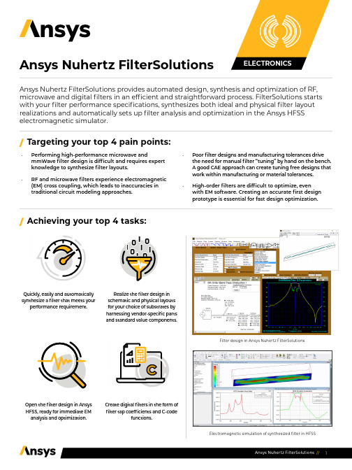
Ansys Nuhertz FilterSolutions Ansys Nuhertz FilterSolutions provides automated design, synthesis and optimization of RF, microwave and digital filters in an efficient and straightforward process. FilterSolutions starts with your filter performance specifications, synthesizes both ideal and physical filter layout realizations and automatically sets up filter analysis and optimization in the Ansys HFSS electromagnetic simulator.•Performing high-performance microwave and mmWave filter design is difficult and requires expertknowledge to synthesize filter layouts.•RF and microwave filters experience electromagnetic (EM) cross coupling, which leads to inaccuracies intraditional circuit modeling approaches. •Poor filter designs and manufacturing tolerances drivethe need for manual filter “tuning” by hand on the bench. A good CAE approach can create tuning free designs that work within manufacturing or material tolerances.•High-order filters are difficult to optimize, even with EM software. Creating an accurate first designprototype is essential for fast design optimization.Open the filter design in AnsysHFSS, ready for immediate EManalysis and optimization.Create digital filters in the form of filter tap coefficients and C-codefunctions./Targeting your top 4 pain points:/Achieving your top 4 tasks:Quickly, easily and automaticallysynthesize a filter that meets yourperformance requirement.Realize the filter design in schematic and physical layouts for your choice of substrates byharnessing vendor-specific partsand standard value components.Filter design in Ansys Nuhertz FilterSolutionsElectromagnetic simulation of synthesized filter in HFSS/W hat differentiates Ansys Nuhertz FilterSolutions? •Performance specification for Layout-to-EM-Optimization in a single smooth workflow•Ability to evaluate the widest range of filter topologies (Bessel, Butterworth, Chebyshev I and II, Elliptic, Gaussian, Delay, Hourglass, Legendre, Matched, Raised Cosine, Tubular, Zigzag, Coupled-Resonator and Cross-Coupled Folded Resonator)•Highly accurate distributed filter layout synthesis based on EM-derived model discontinuities and couplings•Integrates with HFSS for gold-standard EM analysis accuracy and for EM-based optimization•Ability to synthesize filter topologies for analog and digital filter topologies; a single tool for creating accurate filters for both analog and digital signal processing (DSP) applications•Planar filter realizations in the widest available media classes (microstrip, stripline, asymmetric stripline, suspended substrate)/Ansys Nuhertz FilterSolutions provides automatic filter design for: •Lumped filters , presenting synthesized filter schematics that fulfill the filter performance specification. Also provides values for filters realized on PCBs with surface mount or thru-hole discrete components.•Distributed (transmission line filters) - High-performance distributed filters manufactured on microwave or mmWave substrates. These filters are usually realized with transmission lines, open or shorted stubs, vias, coupled lines and cross-coupled transmission line systems. A broad class of microwave and mmWave filters can be realized through precision patterning of conductors on one to three planar substrates.•Digital filters realized in software for digital signal processing (DSP) systems or on microcontrollers. These are software programs, applied to digital signal processing operating on data from digital sampling systems.•Zero-inductor analog filters - Popular at lower frequencies (audio and mid-frequency analog systems), these filters can be realized on PCB process technology with OpAmps in an analog filter format.•IC-based filters in the form of non-programmable digital filters can also be implemented in IC processes utilizing MOSFETS and capacitors to occupy minimum real estate and utilize a switched-capacitor approach.LUMPED (PASSIVE) FILTER MODULE Synthesizes a lumped component filter (single or double-termination) of a selected filter topology to realize user-specified performance characteristics. Standard value components may be applied, with standard (or non-standard) tolerance values for Monte-Carlo analysis. Components have ideal or finite Q or may be based upon vendor component library models.CAPABILITIESDISTRIBUTED FILTER MODULE The Distributed Filter module synthesizes filter layouts on physics-accurate materials, incorporating transmission lines and hybrid lumped elements. Filter layouts can be realized in a variety of substrate formats, including microstrip, suspended substrate and stripline. Physical layouts (including metallization and substrate material properties) can be realized quickly and accurately. Filter layouts are fully parameterized and may be opened in HFSS for immediate EM analysis; all geometries, materials, ports and analysis setups are automatically created. HFSS designs are fully parameterized and optimization setups are provided, so the designer can proceed directly to design optimization to desired response goals.ACTIVE FILTER MODULE Some filter designs call for elimination of inductors and active filter designs with OpAmps can sometimes provide an attractive alternative. The FilterSolutions Active Filter module synthesizes filters to meet user-specified performance requirements in a wide range of filter topologies, such as Thomas, Akerberg-Mossberg, Sallen-Key, Multiple Feedback, Leapfrog, GICs and more. Incorporate OpAmp models from your favorite vendor and include finite Q and gain effects in your active filter designs.SWITCHED-CAPACITOR FILTER MODULEAnother zero-inductor realization: Switched capacitor filters are generally realized in semiconductor processes where capacitors and switching transistors occupy comparatively small spaces. Switched-capacitor filters may be used to realize digital filters and involve sampling circuit topologies. The Switched-Capacitor Filter module synthesizes designs in IIR and FIR realizations, as well as Bilinear, Matched-Z, Step Invariant, Modified Impulse Invariant and custom Z-transform designs.ANSYS, Inc. *******************866.267.9724© 2021 ANSYS, Inc. All Rights Reserved.DISTRIBUTED FILTER DESIGN TOPOLOGIES Lumped Translation, Inductor Translation, Stepped Impedance, Shunt Stub Resonators, Open Stub Resonators, Spaced Stubs, Dual Resonators, Spaced Dual Resonators, Parallel Edge Coupled, Hairpin, Miniature Hairpin, Ring Resonator, Interdigital, ComblineACTIVE FILTER IMPLEMENTATIONS Thomas 1 and 2, Sallen & Key, Parallel, Akerberg, Multiple Feedback (MFB), GIC Biquad, GIC Ladder, Leap FrogDIGITAL FILTER DESIGNS BASED ON THE FOLLOWING DIGITAL TRANSFORMATIONSBilinear, Impulse Invariant (IIR), Matched Z, Step Invariant, FIR Approximation. FIR Filter Types: Rectangular, Bartlett, Hanning, Hamming, Blackman, Blackman-Harris, Kaiser, Dolph-Cheby, Remez, Raised Cosine, Root Raised Cosine, Cosine Filter, Sine Filter, Matched Filter, DelayFilter DIGITAL FILTER MODULE For DSP and sampled systems, FilterSolutions takes user-specified performance specifications and a desired topology and synthesizes filter coefficients to realize the digital filter. Digital transformations are provided to Bilinear, Impulse Invariant, Step Invariant, Matched-Z and Finite Impulse Response (FIR) approximation. Filter realizations are provided in the form of the discrete transfer function, filter tap/block coefficients or as C-code ready for incorporation into a DSP code block.ZMATCH MODULE Zmatch starts with complex load definitions and synthesizes a matching network for maximum power transfer. Includes both Discrete Frequency and Broadband Match modes. Optimal matching networks are provided in lumped, distributed and hybrid realizations.FILTER TYPES AVAILABLE (LUMPED AND DISTRIBUTED FILTERS)Gaussian, Bessel, Butterworth, Legendre, Chebyshev (I and II), Hourglass, Elliptic, Raised Cosine, Matched, Delay FILTER CLASSES AVAILABLE (LUMPED AND DISTRIBUTED FILTERS)Lumped Translation, Inductor Translation, Stepped Impedance, Shunt Stub Resonators, Open Stub Resonators, Spaced Stubs, Dual Resonators, Spaced Dual Resonators, Parallel Edge Coupled, Hairpin, Miniature Hairpin, Ring Resonator, Interdigital, Combline。
EMI Filter Design(the 2nd edition)1. Why Call EMI Filters Black Magic?1.1 A Standard Filter Company Contrasted with an EMI Company 11.2 Power Density Spectrum or Envelope 21.3 Power Transfer 31.4 Specifications: Real World or Imagined 32. Source Impedances of Various Power Lines 92.1 Skin Effect 102.2 Applying Transmission-Line Concepts and Impedances 122.3 Applying Transmission-Line Impedances to Differential and Common Modes 14 2.4 Differences Among Power-Line Measurements 152.5 Simple Methods of Measuring AC and DC Power Lines 153. Various AC Load Impedances 233.1 Resistive Load 233.2 Off-Line Regulator with Capacitive Load 233.3 Off-Line Regulator with Inductor Ahead of the Capacitor 293.4 Power Factor Correction Circuit and Coil 304. The DC Circuit-Load and Source4.1 Various Source Impedances 354.2 Switcher Load 364.3 DC Circuit EMI Solutions or Recommendations 384.4 Lossey Components 404.5 Radiation Emissions 415. Typical EMI Filters: Pros and Cons 425.1 The p Filter 425.2 T Filter5.3 L Filter 475.4 Typical Commercial Filter 495.5 Dissipative Filter 505.6 Cauer Filter 515.7 The R-C Shunt 525.8 Conventional Filters 555.9 Filter Matrix for Line and Load Conditions 556.Differential Mode Components6.1 Capacitor Construction and Self-Resonant Frequency 566.2 Capacitor Design 596.3 Inductor Construction and SRF 706.4 Inductor Design 756.5 Convert from Balanced to Unbalanced or the Reverse 777. Common Mode Components 797.1 Capacitor to Ground 797.2 Z for Zorro 807.3 Converting Common Mode to a Differential Mode Filter 817.4 Equation for the Common Mode via the Differential Mode of Section 7.3 857.5 Common Mode Inductor Used for Differential Mode 907.6 Other Wave Shapes 918. Electromagnetic Pulse and Voltage Transients 928.1 The Three Theories 968.2 Location of the Arrester 998.3 How to Calculate the Arrester 999. What Compromises the Filter?9.1 Two or More Filters in Cascade 1019.2 Poor Filter Grounding 1029.3 The "Floating" Filter 1039.4 Unknown Capacitor in the Following Equipment 1059.5 The Input and Output Too Close Together 1059.6 Gaskets 10610. Waves as Noise Sources 10810.1 The Spike Wave 10810.2 The Pulse Wave 11010.3 The Trapezoid Wave 11010.4 The Quasi-Square Wave 11110.5 Why Differentiate? 11310.6 The Power Spectrum 11411. Study of the Off-Line Regulator 11611.1 With or Without Critical Value of Inductance: Size and Weight Differences of Filters 11611.2 The Added Power Line Harmonic Content Caused by the Off-Line Regulator 12512. Initial Filter Design Requirements12.1 Differential Mode Design Goals 12712.2 Common Mode Design Goals 12912.3 Estimate of Common Mode Load Impedance 12913. Review of A Matrices 13413.1 Chain Matrix A: Transfer Functions 13413.2 Review of A Matrices 13614. Filter Design Techniques14.1 The Unit Matrix 14514.2 The RS Matrix 14614.3 The LINESIM Matrix 14714.4 The LISN Matrix 14814.5 The DIN and DOUT Matrices 15314.6 The RCSHU Matrix 15514.7 The Series Inductor LSER and the Shunt Capacitor CSHU 15714.8 The L Matrix 15814.9 The p Matrix 16014.10 The T Matrix 16114.11 The Cauer Matrix or Elliptical Filter 16215. Matrix Applications 16515.1 The Single-Phase AC Filter 16615.2 The Three-Phase Filter 16915.3 The DC-to-DC Filter 17615.4 Low-Current Filters 17715.5 F0 the Easy Way 17815.6 Remote High-Voltage Supply Fed from a Local DC Power Supply 18316. Applications Using Round or Square Conducting Rods16.1 Very High Current Filters 18716.2 High-Current Second Method 20416.3 High-Current Method 3 21016.4 Review of High-Current Filters 21217. Packaging Information 21617.1 Layout 21617.2 Estimated Volume 21917.3 Volume-Weight Ratio 22218. Questionable Designs 22318.1 28 V at 35 A 22318.2 60 Hz and 120 V with Transorbs 22418.3 The 28 V DC Filter 22718.4 120 V AC 400 Hz 22718.5 Review 22819. Review of Filter Design 22919.1 Filter Design Review 22919.2 Filters in Tandem 23319.3 Q 236Glossary 239Index 249。

科技信息2014年第1期SCIENCE&TECHNOLOGYINFORMATION0引言开关稳压电源核心部分是直流变换器,以内部功率损耗小、转换效率高、体积小、重量轻的优点被广泛应用。
高频功率场效应管的采用,以及新型拓扑技术和集成更多控制和监视功能的小型PWM 集成芯片的出现大大减小了电源的体积。
开关稳压电源工作频率基本在50KHZ 以上,是线性稳压电源工作频率的1000倍以上,使得开关电源滤波效率大大提高。
随着电子技术和应用的迅速发展,开关稳压电源在仪器仪表、计算机、通信、医疗仪器等方面得到了越来越多的广泛应用,发挥了不可取代的巨大作用。
按功率开关的连接方式划分,开关稳压电源分为单端正激式开关电源电路、单端反激式开关电源电路、推挽式开关电源电路。
本文采用单端反激式开关稳压电源电路并在电感电流连续导电模式工作,同时采用高性能固定频率电流模式控制器UC3842驱动开关管,并通过电流电压反馈网络使得输出更精准。
在理论分析同时通过仿真软件saber 进行了验证。
1反激变换器工作原理图1反激变换器图2工作于连续模式原理图下的电感电流如图1所示电路的工作原理如下。
该电路输出接负反馈闭环的采样电压Vom 与参考电压比较,产生的误差信号控制Q1的导通时间,是输出采样电压在负载变化和输入电压变化时跟随参考电压变化。
图中所示变压器为反激变换器类型。
Q1导通时初级绕组就有电流通过,Np 的电压恒定,其电流线性上升,设二极管导通压降为1V,斜率为d i /d t =(V dc -1)/L p 。
在导通之前初级电流上升达到I p =(V dc -1)T on /L p ,L p 为初级励磁电感,整流二极管D1由于反向偏置而截止,因此次级绕组中没有电流I s 通过,初级绕组耦合到次级绕组的能量以磁能形式存在次级绕组中,能量为E =L p (I p )22°当Q1截止时变压器感应的电压与输入电压正好相反,使得二极管正向偏置导通,储存在次级绕组中的磁能以电能形式释放给负载电路,在Q1关断瞬间,次级电流幅值为I s =I p (N p /N m )。
Designation:A1009–05(Reapproved2010)Standard Specification forSoft Magnetic MnZn Ferrite Core Materials for High Frequency(10kHz-1MHz)Power Transformer and Filter Inductor Applications1This standard is issued under thefixed designation A1009;the number immediately following the designation indicates the year of original adoption or,in the case of revision,the year of last revision.A number in parentheses indicates the year of last reapproval.A superscript epsilon(´)indicates an editorial change since the last revision or reapproval.1.Scope1.1This specification covers the requirements to which the specified grades of soft magnetic manganese zinc(MnZn) ferrite materials shall conform.Cores made from these mate-rials are used primarily in power transformers andfilter inductors.1.2The values stated in customary(cgs-emu and inch-pounds)units are to be regarded as standard.The values given in parentheses are mathematical conversions to SI units,which are provided for information only and are not considered standard.2.Referenced Documents2.1ASTM Standards:2A340Terminology of Symbols and Definitions Relating to Magnetic TestingA1013Test Method for High-Frequency(10kHz-1MHz) Core Loss of Soft Magnetic Core Components at Con-trolled Temperatures Using the Voltmeter-Ammeter-Wattmeter Method3.Terminology3.1The terms and symbols used in this specification are defined in Terminology A340.3.2Definitions of Terms Specific to This Standard:3.2.1Inductance Index(AL value)—the self inductance per winding turn squared(L/N2)expressed in units of nanohenries per turns squared(nH/N2).where:n=nano=10–9,nH=inductance in nanohenries,andN=number of turns on winding(example:0.005H with a100turn coil=0.005/(100)2H/N2=500nH/N2).3.2.2Mated Core Set—Two or more core segments as-sembled with the magneticflux path perpendicular to the mating surface.3.2.3Air core inductance,L air,is the inductance of a core with the same magnetic path length and cross-sectional core area but with the relative permeability of air.3.2.3.1Customary UnitsL air54P AN210–9/l1,Hwhere:N=number of turns on winding;A=cross-sectional area of core specimen,cm2;andl1=effective magnetic path length,cm.3.2.3.2SI UnitsL air54P AN210–7/l1,Hwhere:N=number of turns on winding;A=cross-sectional area of core specimen,m2;andl1=effective magnetic path length,m.4.Classification4.1The soft magnetic MnZn ferrite material-type designa-tions for power transformer andfilter inductor materials covered by this specification are listed in Table1,Table2,and Table X1.1.The prefix of the type designations identifies each material’s intended use.Power transformer materials are de-noted with the prefix P andfilter materials are denoted with the prefix F.4.2Thefirst and second digits of the type designations for a power transformer material identify the typical core loss density of the material in mW/cm3,and the remainder of the type designation identifies the temperatures in°C in which the core material must not exceed the maximum core loss density.1This specification is under the jurisdiction of ASTM Committee A06onMagnetic Properties and is the direct responsibility of Subcommittee A06.02onMaterial Specifications.Current edition approved Nov.1,2010.Published December2010.Originallyapproved st previous edition approved in2005as A1009–05.DOI:10.1520/A1009-05R10.2For referenced ASTM standards,visit the ASTM website,,orcontact ASTM Customer Service at service@.For Annual Book of ASTMStandards volume information,refer to the standard’s Document Summary page onthe ASTM website.Copyright©ASTM International.100Barr Harbor Drive,P.O.box C-700West Conshohocken,Pennsylvania19428-2959,United States4.3The last four digits of the type designations forfilter materials identify the typical relative inductance permeability.5.Ordering Information5.1Orders for material under this specification shall include such of the following information as is required to describe the material adequately.5.1.1ASTM specification number including year of issue or revision.5.1.2ASTM soft magnetic MnZn ferrite material-type des-ignation.5.1.3Core shape,size,dimensions,and dimensional toler-ances.5.1.4Whether the core is to be purchased with or without a gap.5.1.4.1The Inductance Index(AL value)or the mechanical gap depth.5.1.4.2If the mated core set is ordered gapped by an Inductance Index(AL value),the purchaser must specify whether the mated core set consists of a gapped core half mated with an ungapped core half or if both core halves are equally gapped.5.1.4.3If the mated core set is ordered gapped by an Inductance Index(AL value),the purchaser must supply the producer with a test coil and the testing conditions(circuit mode,turns on coil,frequency,andflux density).5.1.4.4The tolerance of either the Inductance Index(AL value)or the mechanical gap depth.5.1.5Quantity in pieces.5.1.6Exceptions to the specification or special require-ments.6.Magnetic Properties6.1The size of a soft magnetic MnZn ferrite power trans-former core for relatively high frequencies(>50kHz)is often constrained by the core loss at the operating temperature.Each power material type is identified by a maximum core loss density limit at the temperatures where the core loss density is intended to be below this maximum limit as shown in Table1.6.2The size of a soft magnetic MnZn ferrite power trans-former core for relatively low frequencies(<50kHz)is often constrained by the saturationflux density.The minimum saturationflux density for each power material is shown in Table1.6.3The size of a soft magnetic MnZn ferritefilter inductor core is often constrained by the Inductance Index(AL value) which is dependent on the material permeability.Eachfilter material type is identified by its minimum and maximum relative inductance permeability as shown in Table2.7.Mechanical Properties7.1Typical material constants for soft magnetic MnZn ferrite materials are given in Table X1.2of Appendix X1. 8.Dimensional Tolerances8.1For sintered(unground)dimensions,the tolerances shall be62%.8.2For machined heights,the tolerances shall be60.005in.(0.13mm).8.3For machined gap depths,the tolerances shall be 60.0007in.(0.017mm).9.Workmanship,Finish and Appearance9.1All mating surfaces of the core shall be free of dirt or any other foreign material.Foreign material or surface crazing that interfere mechanically or electrically are not allowed. 9.2The largest dimension of a chip,crack,pit,or surface void must not exceed one third the smallest dimension of the surface under consideration.10.Test Methods10.1Core losses are determined in accordance with the procedure of Test Method A1013.10.2Flux densities are determined by calculatingflux per unit core area from the integrated voltage measured on a secondary winding when the current through the primary winding is set for the desired magnetizingfield strength. 10.3Relative inductance permeability is determined by dividing the measured inductance by the air core inductance.µL5L/L air10.4The inductance is typically measured using a digital LCR meter or equivalent.Procedures described by the manu-facturer in the manuals of the LCR meter should be followed. See also5.1.4.3.10.5The size and shape of the test core specimen is of the producer’s choice but must have uniform cross-sectional core area throughout its magnetic path length and be ungapped.TABLE1Power Transformer Material Type Designations andMagnetic RequirementsASTM Power MaterialTypeMaximum Core LossDensity ASpecifiedTemperaturesThat CoreLoss DensityMust NotExceedMaximumMinimum Saturation FluxDensity BCustomaryUnits,mW/cm3SI Units,W/m3SI Units,°CCustomaryUnits,GSI Units,TP5025-100656500025-10050000.5P509965650009950000.5P707080800007050000.5P7099808000010050000.5P804090900004050000.5A Core loss test conditions:100kHz,1000G(0.1T)at temperature of minimum core loss.B Saturationflux density test conditions:1kHz,15Oe(1200A/m),at25°C.TABLE2Filter Inductor Material Type Designations andMagnetic RequirementsASTM Filter Material TypeMinimum RelativeInductance Permeability,AµLMaximum RelativeInductance Permeability,AµLF010K700013000F500037506500F300022503900A Relative inductance permeability test conditions:100kHz,5G(0.0005T),at25°C.11.Lot Identification11.1The producer shall assign a lot identification code that can be used to identify the specific raw material lots,moldable powder lot,kiln firing,and grinding lot.12.Material Certification Report12.1When specified in the purchase order or contract,the purchaser shall be furnished certification that samples repre-senting each lot have been either tested or inspected as directed in this specification and the requirements have been met.When specified in the purchase order or contract,a report of the test results shall be furnished.12.1.1For power transformer materials,the producer shall include with each shipment a certified report of the core loss,sintered dimensions,and Inductance Index (AL value)or gap length.12.1.2For filter materials,the manufacturer shall include with each shipment a certified report of the Inductance Index (AL value).12.2The material certification report shall carry the lot identification.13.Keywords13.1core loss density;high frequency magnetic materials;MnZn;permeability;soft ferrite materialsAPPENDIX(Nonmandatory Information)X1.PROPERTIESASTM International takes no position respecting the validity of any patent rights asserted in connection with any item mentioned in this ers of this standard are expressly advised that determination of the validity of any such patent rights,and the risk of infringement of such rights,are entirely their own responsibility.This standard is subject to revision at any time by the responsible technical committee and must be reviewed every five years and if not revised,either reapproved or withdrawn.Your comments are invited either for revision of this standard or for additional standards and should be addressed to ASTM International Headquarters.Your comments will receive careful consideration at a meeting of the responsible technical committee,which you may attend.If you feel that your comments have not received a fair hearing you should make your views known to the ASTM Committee on Standards,at the address shown below.This standard is copyrighted by ASTM International,100Barr Harbor Drive,PO Box C700,West Conshohocken,PA 19428-2959,United States.Individual reprints (single or multiple copies)of this standard may be obtained by contacting ASTM at the above address or at 610-832-9585(phone),610-832-9555(fax),or service@ (e-mail);or through the ASTM website ().Permission rights to photocopy the standard may also be secured from the ASTM website (/COPYRIGHT/).TABLE X1.1Typical Magnetic Properties for Power Transformer MaterialsASTM Power Material TypeTypical Core Loss Density at Temperature of Minimum Core Loss A Temperatures of Minimum Core LossCustomary Units,mW/cm 3SI Units,W/m 3SI Units,°C PS025–100505000025–100P5099505000099P7070707000070P70997070000100P8040808000040ACore loss test conditions:100kHz,1000G (0.1T)at temperature of minimum core loss.TABLE X1.2Physical and Mechanical Properties for Soft Magnetic MnZn Ferrite Typical Material ConstantsCoefficient of linear expansion10x 10–6/°C Tensile strength 7ksi (50MPa)Compressive strength60ksi (410MPa)Density4.8g/cm 3(4800kg/m 3)。
滤波拓扑概况用于D类功率放大器的滤波器拓扑共有三种:(1) FB-C,铁氧体磁珠和电容;(2) LC,电感和电容;以及(3) “无滤波器”。
某个特定设计应该选择哪种滤波技术,取决于应用的扬声器电缆长度和PCB布局。
下面是这三种滤波器拓扑的优缺点:FB-C滤波如果扬声器电缆长度适中,FB-C滤波足以满足EMI限制。
与LC滤波相比,FB-C滤波方案更为精简,成本效益更高。
但是,由于只能在频率大于10MHz的情况下生效,FB-C滤波的应用围受到很大的限制。
而且,在频率低于10MHz的情况下,如果扬声器电缆走线不合理,也会导致传导辐射超标。
LC滤波相比之下,LC滤波可以在频率大约为30kHz的情况下即开始起到抑制作用。
当某设计中所用的电缆线较长,而PCB布局又不是很好时,LC滤波无疑是一个“保险的”选择。
但是,LC滤波需要昂贵而庞大的外部元件,这显然不适合便携式设备。
而且,当频率大于30MHz,主电感会自谐振,还会需要额外的元件来抑制电磁干扰。
“无滤波器”滤波“无滤波器”放大器拓扑是最具成本效益的方案,因为它省去了额外的滤波元件。
采用较短的双绞线扬声器电缆时,D类放大器完全可以满足电磁兼容性标准。
但是,和FB-C滤波一样,如果扬声器电缆走线不合理,可能出现传导辐射超标。
还需注意,Maxim的D 类放大器也可以实现“无滤波”工作,只要在放大器的开关频率下扬声器是感性负载。
在输出电压进行转换时,转换频率下的大电感值可使过载电流保持相对恒定。
图1:TPA3001D1结构图图2显示了典型的PWM信号是如何从图1中的比较器功能块形成的。
可将音频输入与2 50-kHz的三角波相比较。
当音频输入电压大于250-kHz三角波电压时,非反相比较器输出状态为高,而当250-kHz三角波大于音频信号时,非反相比较器输出状态为低。
非反相比较器输出为高时,反相比较器输出为低;而当非反相比较器输出为低时,反相比较器输出为高。
平均PWM非反相输出电压VOUT+(avg) 为忙闲度乘以电源电压,此外D 表示忙闲度,或"开启"时间t(on) 除以总周期T。