W 系列液压扳手说明书
- 格式:pdf
- 大小:4.13 MB
- 文档页数:20
液压扳手的使用方法及注意事项液压扳手的使用方法步骤一:准备工作在使用液压扳手之前,需要进行一些准备工作,以确保安全和顺利的操作。
1.确保工作区域清洁整齐,没有杂物和障碍物。
2.检查液压扳手的工作状态和油液是否充足,如有问题及时处理。
3.穿戴适当的个人防护装备,如安全帽、护目镜和手套。
步骤二:正确使用液压扳手1.根据需要选择合适的液压扳手型号和规格。
2.将液压扳手的开关置于关闭状态。
3.将液压扳手的活塞置于松开状态,确保可以自由移动。
4.将液压扳手的夹具放置在需要操作的螺栓或螺母上。
5.轻轻转动液压扳手的开关,使其夹紧螺栓或螺母。
6.逆时针旋转液压扳手的开关,使其施加力矩。
7.当达到所需力矩时,立即停止旋转液压扳手的开关。
8.将液压扳手的开关置于关闭状态,释放夹紧力。
9.将液压扳手从螺栓或螺母上移开。
步骤三:注意事项为了确保使用液压扳手的安全和有效性,需要注意以下事项:1. 安全操作•在使用液压扳手之前,务必仔细阅读和理解使用说明书。
•在使用液压扳手时,要保持专注,避免分心或受到干扰。
•不要将手指或其他物体放入液压扳手的夹具中。
•不要在液压扳手工作时进行维修或调整。
•使用液压扳手时,要注意周围的安全,确保没有人员或物体受到伤害。
2. 维护保养•定期检查液压扳手的工作状态和油液是否充足,如有问题及时处理。
•使用液压扳手后,清洁并储存于干燥的地方,避免受潮和腐蚀。
•定期对液压扳手进行维护保养,如更换密封件和润滑油。
3. 其他注意事项•在使用液压扳手时,要根据具体情况选择合适的工作方式和力矩大小。
•不要超过液压扳手的额定工作范围,以免损坏设备或导致意外发生。
•在使用液压扳手时,要注意周围环境的温度和湿度,避免影响工作效果。
总结液压扳手是一种常用的工具,它可以帮助我们进行螺栓和螺母的紧固和松开。
在使用液压扳手时,我们需要注意安全操作和维护保养,以确保工作的安全和有效性。
通过正确的使用方法和遵守注意事项,我们可以更好地利用液压扳手完成各种工作任务。
WX系列中空液压扳手操作与维护手册始创立于1899年的工业动力与顶升设备的制造者Phone: (800) 323-9114 • Fax: (708) 865-0894 •注意WX 2, 4, 8, 16, 32 系列中空液压扳手在设计上是应用于在最小施工空间内安装和拆卸螺纹紧固件,在石油平台、电厂、钢结构工地和其他现场,其要求螺栓安装时具有精确的大扭矩和螺栓预紧与拆卸时施加的最大扭矩。
Simplex不能负责在应用中进行对工具进行更改,并且这种更改没有得到Simplex的确认。
警告本手册中包括重要的安全信息在使用工具前阅读本手册雇主负有将这本手册中的信息交到操作者手中的责任不遵守下面的警告可能导致人身伤害。
操作前准备工作•始终按照相应的安全规范来操作、检查和维护本工具,参考标准:美国国家标准ANSI B30.1-液压油缸和千斤顶•本液压扳手使用气动或电动液压泵驱动。
当泵与扳手连接时遵守泵的安全和使用说明。
•仅在设备额定的压力和扭矩内使用本液压扳手。
•仅可将泵的最高压力设置为10,000psi (700公斤压强)•使用一对额定压力等级为10,000psi (700公斤压强)的液压软管连接泵和扳手•不要互换扳手上的进口雌雄旋转接头或软管端头的连接接头。
反接进口接头将使扳手的工作方向颠倒以致损坏工具。
•不要使用损坏、磨损或老化的软管和接头。
确保软管无裂缝、开口或泄漏。
•使用软管上的快速连接接头将液压扳手和泵连接起来。
确保弹簧加载保持圈完全到位,并且安全环紧靠弹簧加载保持圈旋紧,以防止快速接头在压力下弹开。
•当软管连接好没有打压前,充入液压油。
在泵启动前,确保泵的油箱液压油位。
•不可将任何标签和危险警示标记撕下。
液压扳手使用•不要用手推拉充压的软管。
飞溅的液压油可能溅入皮肤,导致严重的伤害。
如果液压油溅入皮肤,请立即看医生。
•决不要向未连接起来的半个快速接头打压•当操作和维护液压扳手时始终佩戴保护眼镜•操作工具时始终佩戴安全帽、手套和工作服。
液压扭矩扳手使用方法1. 液压扭矩扳手是一种用于紧固螺栓和螺母的工具,通过液压力量来提供精确的扭矩控制。
2. 在使用液压扭矩扳手之前,需要先将扳手连接到液压泵或液压动力源。
3. 调整液压泵的压力,确保扭矩扳手能够提供所需的扭矩数值。
4. 确保螺纹连接牢固,以免泄漏或失去扭矩精度。
5. 在使用液压扭矩扳手时,应该遵循制造商的建议和操作手册。
6. 在紧固螺栓或螺母之前,应该先了解所需的扭矩数值,以便进行正确的调整。
7. 使用液压扭矩扳手时,应该避免过度使用力量,以免损坏工件或扭矩扳手本身。
8. 确保在使用液压扭矩扳手时佩戴安全手套和护目镜,以确保安全操作。
9. 在使用液压扭矩扳手时,应该遵循相关的安全标准和操作规程。
10. 在使用液压扭矩扳手时,要时刻注意周围的工作环境,确保周围没有人员或障碍物。
11. 液压扭矩扳手的使用过程中需要保持润滑和清洁,以确保正常运行。
12. 在操作液压扭矩扳手时,需要确保其工作面的环境温度在适宜范围内,以免影响扳手的工作效率。
13. 使用液压扭矩扳手时,应该确保螺栓或螺母的工作表面干燥和清洁,以确保精确的扭矩传递。
14. 在操作液压扭矩扳手之前,应该检查扭矩扳手的工作状态和液压系统的工作状态,确保一切正常。
15. 在使用液压扭矩扳手时,应该确保螺栓或螺母的工作位置处于适当的角度,以便正确施加扭矩。
16. 在使用液压扭矩扳手时,要确保其扭矩值的准确性,可通过校准仪器来检验。
17. 当使用液压扭矩扳手时,应该避免在过载或超过额定扭矩范围内操作,以免损坏工具。
18. 在操作液压扭矩扳手时,应该遵循正确的工作程序和工具使用方法,以确保工作效率和安全性。
19. 在使用液压扭矩扳手之前,需要对其进行检查和维护,确保其正常工作。
20. 在使用液压扭矩扳手时,需要确保相关的液压系统与配件齐全齐全,以确保工作的连贯性。
21. 使用液压扭矩扳手时,应该根据工件的要求选择合适的扭矩数值,以确保紧固件的正常工作。
液压扭力扳手操作说明书前言亲爱的用户:在利用该扭力扳手器具前,建议您认真学习这些指导条款。
ITH GmbH的扭斩扳手工具是按DIN ISO 9001标准进行设计与加工的。
平安方面遵循CE标准规定的要求。
超级感激他们的先进设计,ITH扭力扳手利用平安操作间单。
但是,在操作利历时,有很多事项必需注意。
基于那个缘故,请确信所有利用该设备工作的人员,都阅读过而且明白得参数表格的第七章节的内容,其题目为“平安注意事项”。
:++49/(0)291/9962-0:++49/(0)291/9962-11目录章节内容文件1.0 扭力扳手(收发)地址及(技术)参数。
2.0 EEC认证。
3.0 实验报告。
4.0 扭力值表格。
5.0 扭力扳手(组合体)操作指导。
6.0 简明操作指导。
7.0 平安注意事项。
8.0 高压泵备用部件清单。
9.0 高压泵备用部件图。
10.0 扭力扳手备用部件图及部件清单。
11.0 扭力值显示表操作指导。
10.0 扭力扳手压力与扭力参数。
11.0 备用部件及附属部件。
注意事项:这些指导条款是按DIN8418标准VCMA-相关文件确立的。
若是您在具体需要时,对本文要求进行补充,欢迎您的建议。
专门针对幸免意外事故的发生。
1.0 扭力扳手组合体的大体参数表格1.1 (供发)地址:1.1.1 制造方:ITH GmbH1.1.2 购买方:Voith Siemens Hydro GmbH & Co. KG1.1.3 交货日期:04/12/011.2 扭力扳手组合体技术参数1.2.1 扭力扳手1.2.2 压力站1.2.3 软管1.2.4 连接配件1.2.5 弯管接头2.0 EC认证2.0 实验装置3.0 校对:A:扭臂长度:1米 D:实验力矩:B:试重重量:50千克 E:显示值按转换因素换算C:读出数值:2774.0 显时值表格注明:5.0 扭力扳手操作说明5.1 连接主电源时,用EEC连接部件的插头插入,确信有效电源有三相,并有一个接地(230伏单相交流,只用一相有效电源)。
液压力矩扳手安全操作规程引言液压力矩扳手是一种常用的工业工具,用于紧固高强度螺栓和螺母。
本文档旨在介绍液压力矩扳手的安全操作规程,以确保操作人员的人身安全和设备的安全运行。
液压力矩扳手简介液压力矩扳手是一种通过液压系统控制扭矩输出的工具。
其主要由一个液压缸、一个扭矩输出部件和一个控制系统组成。
液压缸通过液压油的压力来产生扭矩,扭矩输出部件将扭矩传递给螺栓或螺母,控制系统用于控制扭矩的大小。
安全操作规程1. 熟悉设备在使用液压力矩扳手之前,必须熟悉设备的结构和工作原理。
阅读设备的操作手册,并了解各个部件的功能和操作方法。
2. 穿戴个人防护装备在操作液压力矩扳手时,必须穿戴个人防护装备,包括安全帽、防护眼镜、防护手套和防滑鞋。
这些装备能有效地保护操作人员的人身安全。
3. 检查设备在使用液压力矩扳手之前,必须检查设备是否完好无损。
检查液压缸、扭矩输出部件和控制系统是否有漏油和磨损。
确保液压系统的工作压力在设备规定范围内。
4. 固定工件在使用液压力矩扳手之前,必须将工件固定好。
工件必须保持稳定,避免发生意外滑动或移动。
5. 设定扭矩根据工作需要,设定正确的扭矩数值。
在设定扭矩之前,必须确保设备的工作压力稳定,以及液压缸和扭矩输出部件的密封性良好。
6. 正确使用液压力矩扳手将液压力矩扳手的扭矩输出部件对准需要紧固的螺栓或螺母,并将其固定。
然后,打开液压系统使其工作。
在液压缸施加压力的同时,扭矩输出部件会旋转并产生扭矩。
当扭矩达到设定值时,及时停止施力。
7. 维护和保养定期检查和保养液压力矩扳手,确保其正常工作。
清洁设备表面,清理液压系统中的杂质和沉淀物。
定期更换液压油,并根据操作手册对设备进行润滑。
8. 遵守安全操作规程在使用液压力矩扳手时,必须遵守相关的安全操作规程。
不得擅自改变设备的结构和工作参数。
定期接受相关培训,提高操作技能和安全意识。
总结液压力矩扳手是一种重要的工业工具,但在操作过程中存在一定的安全风险。
沃顿WODEN汇总了有关液压扳手的使用方法1) 线控开关按钮功能:按下(RUN)按钮,油缸推进;松开按钮,油缸自动复位。
按下(STOP)按钮,油泵停止。
2) 液压泵起动前,先打开(旋松)压力调节阀,再打开电源(ON),检查液压泵运转是否正常;然后点动线控按钮数次,运转数分钟,将压力调节到所需预设压力值。
额定压力为70Mpa。
3) 调节压力时,应按住线控按钮,当听到扳手“啪”一声,快速释放杆跳下,扳手到位停止转动,压力表从0急速上升,另一只手缓慢向上调节压力调节阀,并可用锁紧螺母锁紧。
4) 空运转,将液压扳手放在地上,按下(RUN)钮,扳手开始转动,当听到扳手“啪”的一声,则扳手到位停止转动;此时松手按钮,扳手自动复位,当再次听到扳手“啪”的一声,则复位完成。
即:RUN—推进—啪—松手—复位—啪。
重复做几个工作循环,观察扳手转动无异常时,可将扳手放至螺帽上作业。
5) 拆松螺帽:将液压泵压力调到最高(70Mpa),确认扳手转向为拆松方向,找好反作用支点,靠稳,反复进行油缸的进退工作循环。
如果拆不动,则采取除锈措施,如果螺母还拆不动,则换用更大型号的液压扳手。
6) 锁紧螺帽:查扭矩对应表确定液压泵的压力设定,确认扳手转向为锁紧方向,找好反作用支点,靠稳,反复进行油缸的进退工作循环,直至螺帽不动为止。
7) 液压扳手作业停止时,应及时关闭电源。
8) 工作完毕后切断电源,按卸压阀卸去系统余压,完全打开压力调节阀,再拆卸油管。
9) 扳手搬运时必须卸下油管后进行。
一、操作前检查:1) 易燃易爆环境不得使用电动液压泵,应使用气动液压泵。
2) 检查电动泵作业电压满足220V。
3) 检查液压扳手泵压力调整、过滤、喷油三联装置,进行排水、添加46#抗磨液压油、进气压力调整。
4) 检查液压油泵油标的油位在0线以上,液压油清澈透明。
应添加专用液压油, 严禁混用其它油。
5) 检查超高压软管有无折弯等损伤;连接时先理顺软管不得纠结,插头插座擦干净无污物,将快装接头插到底,确保连接可靠,并用手将螺纹套锁紧,否则快装接头内单向阀未顶开无法正常供油。

HI-FORCE HTWP21系列气动扳手泵操作手册Hi-Force HTWP21 系列气动扳手泵是特别为操作工作压力为700 bar (10 000 psi) 的双作用高压液压扭矩扳手设计,本使用说明适用于以下型号:HTWP2140P –气源压力7.0 bar气动扳手泵使用前请仔细查看泵上铭牌的产品信息。
安全说明在操作泵之前请认真仔细阅读这些操作说明和安全事项否则可能会导致人身伤亡或设备损坏●请确认连接到设备上的泵是完好无损的,并且是在700 Bar压力下进行操作。
●在操作泵时,总是放置在平坦的水平面上。
●在使用或者运输时,不要将泵倒置,侧放。
●检查软管是否损坏或者磨损。
不要使用已经磨损,弯折,损坏和泄露的软管。
●不要使用软管来拖拉泵或者扭矩扳手。
●不要使用已经大幅度弯折和扭曲的软管。
●不要手拉带有压力的软管。
从软管中漏出的带有压力的液压油可以穿透皮肤。
如果液压油进入皮肤,这是十分严重的医疗紧急情况。
需要立即看医生。
●在液压软管和TWS/TWH还没有连接到泵的时候,请不要启动泵。
●在操作泵时,请配带好眼,耳和手的防护设备。
●当需要对泵进行维护保养或者调试时,请断开气源。
(除了压力释放阀的调试)HI-FORCE HTWP21系列气动扳手泵操作手册零件识别请参考下图:1. 油箱2. 油温/位表3. 注油呼吸盖4. 电机5. 油压力表6. 可调式压力释放阀7. 扳手前进接头 (最大工作压力700Bar)8. 扳手回缩接头 (最大工作压力700Bar)9. 放油塞10. 空气压力表11. 线控信号连接12. 线控气源连接13. 空气压力调节器14. 空气润滑器控制15. 空气润滑存储杯16. 线控软管17. 控制面板18. 排气消声器19. 气源进口G3/8” (3/8” BSP)HI-FORCE HTWP21系列气动扳手泵操作手册HI-FORCE HTWP21系列气动扳手泵操作手册操作前准备打开包装后立即检查泵是否无损坏,一旦发现损坏请立即联系承运商。
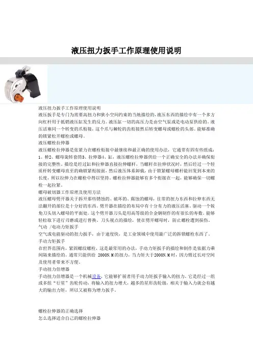
液压扭力扳手工作原理使用说明液压扭力扳手工作原理使用说明液压扳手是专门为需要高扭力和狭小空间约束的当地描绘的,液压东西的描绘中有一个多方向杠杆用于抵销液压缸发生的反力。
液压缸一切的高压力是由空气泵或是电动泵供给的。
液压活塞同一个转变的爪衔接,这个爪与棘轮的齿衔接然后转变螺母或螺栓的头部。
能够准确的锁紧松开螺栓或螺母。
液压螺栓拉伸器液压螺栓拉伸器是张紧力在螺栓衔接中最继续和最正确的使用办法,它通常有四有些组成:1、桥2、螺母旋转套筒3、拉伸器4、缸,液压螺栓拉伸器供给一个正确安全的办法并确保衔接的完整性。
描绘是经过缸和拉伸器直接拉伸螺杆,当螺杆在拉伸状况时,然后经过一个轻质杆转变螺母直至的确锁紧衔接面,然后液压体系卸载,由于锁紧螺母螺杆能回复到本来的长度,所以拉伸力在螺栓中得以坚持。
螺栓拉伸器能够有多个衔接在一起,能够确保一切螺栓一起拉紧。
螺母破切器工作原理及使用方法液压螺母劈开器关于拆开那些锈蚀的、破坏的、腐蚀的螺母,往常的扭力东西和拉伸东西无法翻开的部位是十分好的东西。
劈开器在描绘的布局中有十分有力的液压活塞。
驱动一个锐角刀头切入螺母的平面处。
这个劈开器刀头是用高等级的合金钢制作的有很长的寿数。
能够轻松取下进行刃磨或进行替换。
刀头视点的描绘,使在劈开螺母时,防止螺栓遭到损伤。
气动 /电动力矩扳手空气或电能驱动的扭力扳手,由于速度快,是工业领域中使用最广泛的拆锁螺栓东西了。
手动力矩扳手在世界范围内,紧固螺纹螺栓,这是最常用的办法,手动力矩扳手的描绘和制作是依据力乘间隔来描绘的。
通常只能供给 2000N.M的扭力,当力矩大于2000N.M时,因力臂过长对空间及使用者带来不方便。
手动扭力倍增器手动扭力倍增器是一个机械设备,它能够扩展者用手动力矩扳手输入的扭力。
它是经过一组或多组“行星”齿轮传动,将输入的扭力增大,越多的星形齿轮级,相关于输入力就会有越大的输出力矩,所以又被称为增力扳手。
螺栓拉伸器的正确选择怎么选择适合自己的螺栓拉伸器当前常用的两种紧固方法有两种:1:螺栓拉伸方法,在描绘中通常给出的是预紧力为多少KN;螺栓拉伸方法是运用液压油缸直接对螺栓端头施加外力,将螺栓拉伸到所需长度,然后用手悄悄将螺母拧紧,使施加的载荷得以保存。
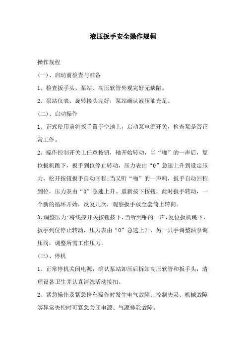
液压扳手安全操作规程
操作规程
(一)、启动前检查与准备
1、检查扳手头、泵站、高压软管外观完好无缺陷。
2、泵站仪表、旋转接头完好,泵站确认液压油充足。
(二)、启动操作
1、正式使用前将扳手置于空地上,启动泵电源开关,检查泵是否正常工作。
2、操作控制开关上任意按钮,轴开始转动,当“啪”的一声后,复位扳机跳下,扳手到位停止转动,压力表由“0”急速上升到设定压力,松开按钮扳手自动回程;当又听“啪”的一声响,扳手自动回程到位,压力表由“0”急速上升。
重新按下按钮,此时扳手转动,一个新的循环开始,反复几次,观察扳手放至套筒上转向。
3、调整压力:将线控开关按钮按下,当听到啪的一声,复位扳机跳下,扳手到位停止转动,压力表由“0”急速上升,另一只手调整油泵调压阀,调整所需工作压力。
(三)、停机
1、正常停机关闭电源,确认泵站卸压后拆卸高压软管和扳手头,清理设备卫生并认真清洗活动接扣。
2、紧急操作及紧急停车操作时发生电气故障、控制失灵、机械故障等异常失控时可紧急关闭电源、气源排除故障。
Char-Lynn®Spool Valve Hydraulic MotorsW Series Geroler ® Motors 400ek a r B g n i k r a P h t iw Repair InformationHousing2StationaryPiston Housing ArrayNote:3Disassembly1 Cleanliness is extremely important when repairing hydraulic motors. Work in a clean area. Before disconnecting the hydraulic motor thor-oughly clean the exterior. Remove motor from application before disassembly; drain the oil from the motor.Required Tools• 5/16 inch Hex Key• Bullet for Shaft Seal Installation - Eaton Tool No. 600633• Bearing Removal Tool - Eaton Tool No. 600636• Bearing Installation Tool - Eaton Tool No. 600637• Torque wrench - 68 Nm [600 lb-ft] capacity• Seal Press Tool - Eaton Tool No. 600642• Piston/Seal Installation Tool - Eaton Tool No. 600705Alignment studs (2)456HousingShaft, OutputShaft with Pressure Limiting ValvesBrake Shaft SealRing, RetainingHousingPress Bearing and Retaining Ring out Frontof Housing.Bearing, BallRing, RetainingHousing5 Remove bearing and retaining ring with special tool; insert tool cone end first and drive these two parts out from back side of housing. Seal will be damaged when tool is inserted and must be replaced upon reassembly.6 Remove retaining ring, washer, backup washer and pressure seal from housing.7 Check all mating surfaces. To reduce the chance of leakage, replace any parts that have scratches or burrs. Wash all metal parts in clean solvent. Blow them dry with pressurized air. Do not wipe parts dry with paper towels or cloth. Lint in a hydraulic system will cause damage.4 Remove retaining ring from front of housing (motor disassemblyat this point no longer in vertical position).Housing78Reassembly8 Position housing in the vertical position on a clean smooth surface,lubricate pressure seal with petroleum jelly and insert in housing, seal lip in the down position. Use seal press tool No. 600642 and press seal into position in housing.9 Place backup washer, washer, and retaining ring on top ofpressure seal. Make sure retaining ring is fully engaged in groove in housing.Ring, Retaining HousingWasher, Backup (Thin)Pressure Seal in PlaceWasher (Thick)Press Seal into Housing910 Place seal bullet over shaft. With bullet and shaft seal surface lubricated with petroleum jelly, place shaft on a clean smooth hard surface, output end of shaft up. Position housing over shaft and carefully lower housing over bullet and shaft.ShaftSeal BulletHousingPress Bearing and Retaining Ring into Housing11 Remove bullet from shaft end and place retaining ring and bearing on shaft, along with bearing driver tool. Press these parts into housing.IMPORTANT NOTE: When handling motor assembly without bearing installed, extra care should be taken to make sure that the back end of the Output Shaft always stays flush with the back end of housing surface. If Output Shaft moves, in either direction,more than 0,79mm [1/32 in.], Output Shaft should be removed from the housing so that the Seal may be inspected for cuts. If necessary, replace Seal per steps 8 and 9,and then reinstall Output Shaft per step 10.1012 Install retaining ring, making sure retaining ring is fully engaged in ring groove in housing.13 Reposition housing shaft end down. The illustrations have been created from the master parts drawing and are for part reference only.14 Install seal in seal groove of housing.15 Place drive in shaft, engage spline. Mark drive using mark on shaft as a reference point.Timing procedure is shown on page 13.16Place Geroler over drive (seal groove up), star point or star star valley aligned with mark on drive per your rotation preference.17 Align bolt holes on Geroler with housing holes. Install two alignment studs * into bolt holes one on each side of valve housing.Ring, RetainingHousingGeroler* Note: Alignment studs are recommended for reassembly, studs will assist in the alignment of remaining parts.Alignment Studs (2)W Series with Parking Brake1118 Install seal in seal groove of Geroler.19 Install spacer plate on Geroler.20 Place drive collar over the drive extension. The collar should slide over the extension smoothly and turn freely on the extension.21 Place the brake shaft over the drive collar, align the flat sides of the collar with the flat sides of the inner form on the brake shaft.The brake shaft should lay flat against the spacer plate.22 Install seal into brake shaft housing seal groove (needle bearing bore side).Brake Shaft Housing 23 Align the brake release port (in the brake shaft housing) with the main flow ports in the valve housing; all three ports should be in the same plane, then slide brake shaft housing down alignment studs onto spacer plate.Note: The OD of the brake shaft should slide into the needle bearing smoothly. Check to see that the drive collar/brake shaft interface was assembled properly, twist the brake shaft back and forth, there should be very little play—if the brake shaft can be turned back and forth and seems to be a sloppy fit, reassemble parts (steps 20-23).28 Rotate piston housing so that the face with the small diameter thru hole faces the brake shalt housing. Place the piston housing on the brake shaft housing and align the 3,17 [.125] dia. angled hole with the 3,17 [.125] dia. straight hole coming out of the brake shalt housing. 29 Place the washer (eliminated early year 2000 - page 3 shows early version) into the counterbore in the piston. The washer should lay flat.30 Place one spring (belleville) into the piston counterbore, the OD of the belleville washer should touch the washer. Place a second spring (belleville) into the piston counterbore with its ID touching the ID of the first belleville washer.31 Install both seals into the two grooves in the piston housing.32 Place the end cap onto the piston housing with the counterbore surface facing the piston housing, also check to see if the top of the identification tag is parallel with the main port face.33 Dip cap screw threads in clean hydraulic oil prior to assembly.34 Insert and finger tighten 5 of the 7 cap screws through; the end cap, piston housing, brake shaft housing, spacer plate and then into the threaded housing. Remove alignment studs (2) and replace each with remaining cap screws.Note: Cap screws have a sealant under the head.35 Pre-torque screws (in a crisscross pattern) to 34 Nm [300 lb-in],re-torque (in a crisscross pattern) to 48,1 - 53,7 Nm [425-475 lb-in].12Motor Timing13Installation of piston seals27Evenly apply 0.1 to 0.15 cc seal lubricant to large U-cup piston seal.27A Carefully stretch U-cup piston seal over the piston and into the large groove on the piston. The groove in the piston seal (which makes that seal cross section look like a U) should be aligned toward the small piston diameter (actuator end) of the piston. Verify that the U-cup is not twisted in the groove (assembly procedure 1 above).27B Evenly apply 0.1 to 0.15 cc seal lubricant to small o-ring.27C Carefully stretch o-ring over the small piston diameter and into the small groove on the piston. Verify that o-ring in not twisted in the groove.27D Press piston with seals into piston assembly tool No. 600705 (assembly procedure 2 and 3 above).27E Place tool with piston and seals onto piston housing and using the your hand, a soft mallet, or a press; push the piston into the piston housing until it is recessed in the housing.27F Rotate piston housing so that the face with the small diameter thru hole faces the brake shalt housing. Place the piston housing on the brake shaft housing and align the 3,17 [.125] dia. angled hole with the 3,17 [.125] dia. straight hole coming out of the brake shalthousing.12345ToolPiston Housing14Notes:15W Series with Parking BrakeFor More Detailed Information Contact Eaton Hydraulics 14615 Lone Oak Road Eden Prairie, MN 55344.Specifications and performance data, Brochure 10-01-109Replacement part numbers and kit information — Parts Information 06-01-165.Each Order Must Include the Following:How to Order Replacement Parts 1. Product Number2. Date Code3. Part Name4. Part Number5. Quantity of Parts© 2008 Eaton Corporation All Rights Reserved Printed in USADocument No. C-MOLO-TS028-E Supersedes 07-01-158December 2008EatonFluid Power GroupHydraulics Business USA 14615 Lone Oak Road Eden Prairie, MN 55344USATel: 952-937-9800Fax: 952-294-7722/hydraulicsEatonFluid Power GroupHydraulics Business Europe Route de la Longeraie 71110 Morges SwitzerlandTel: +41 (0) 21 811 4600Fax: +41 (0) 21 811 4601EatonFluid Power GroupHydraulics Business Asia Pacific11th Floor Hong Kong New World Tower 300 Huaihai Zhong Road Shanghai 200021 ChinaTel: 86-21-6387-9988 Fax: 86-21-6335-3912。