4编码器使用说明
- 格式:docx
- 大小:281.21 KB
- 文档页数:9

4线至2线编码器是一种常用的数字电路,用于将4条输入线的组合信号编码成2位二进制代码输出。
在电路图中,4线至2线编码器通常使用特定的符号标识,以便工程师和技术人员能够清晰地理解其功能和结构。
下面将介绍4线至2线编码器的电路符号及其含义。
1. 电路符号的基本构成4线至2线编码器的电路符号通常由矩形框表示主体部分,内部有4条输入线和2条输出线。
输入线和输出线的连接方式一般以箭头或者直线的形式表示,以区分其输入和输出的方向。
另外,符号的周围可能会有标注文字或者符号,用于表示特定的功能或者特性。
2. 输入线和输出线的标识在4线至2线编码器的电路符号中,输入线通常用A、B、C、D等字母来表示,分别对应编码器的4条输入线。
输出线则用Q0和Q1等标识来表示,分别对应编码器的2位二进制代码输出。
这样的标识方式既简洁明了,又能够准确地表达信号的传输和编码关系。
3. 标注文字的含义在电路符号的周围可能会有标注文字,用于表示特定的功能或者特性。
可以在符号上方标注“4-to-2 Encoder”,用以说明该电路符号代表的是4线至2线编码器。
还可以标注输入线和输出线的具体含义,以及符号所代表的器件型号或者规格参数等信息。
4. 特殊形式的电路符号除了基本的矩形框和箭头形式外,有时候4线至2线编码器的电路符号还可能采用其他特殊形式,以更好地反映其内部结构和工作原理。
可以在符号内部绘制逻辑门的标志,以说明编码器的内部是由何种逻辑门组成的。
这样的特殊形式可以在一定程度上提高电路符号的直观性和表达能力。
总结起来,4线至2线编码器的电路符号是工程师和技术人员交流交流的重要工具,其合理的构成和标识方式能够有效地传达编码器的功能和结构信息。
了解和掌握4线至2线编码器的电路符号及其含义对于理解和设计数字电路具有重要的意义。
希望通过本文的介绍,读者能够对4线至2线编码器的电路符号有一个清晰的认识,并能够在实际工作中熟练运用。
电子电路中,4线至2线编码器是一种常见的数字逻辑电路,用于将4个输入线的组合信号转换成2位的二进制代码输出。

依爱消防编码器使用方法
《依爱消防编码器使用方法》
一、产品特点
依爱消防编码器采用最新的4位数字码技术,它不仅精巧小巧,而且功能强大,可靠性高。
它可以用来编码防火墙上的门窗或其他闭合空间存放的火灾物品,可以更容易地识别出来,从而更有效地更快扑灭火灾并减少损失。
二、使用方法
1、将依爱消防编码器安装在防火墙上的门窗上,以便及时识别和跟踪材料存放的空间。
2、调整编码器,将其设置为4位数字码,使用者可以随意选择,但必须记住每个编码的内容,以便及时识别和跟踪。
3、在使用过程中,用户应仔细检查编码器,确保它处于良好的状态。
4、如果在使用过程中发现任何异常情况,应及时进行排查和解决,以保证编码器的正常使用。
5、如果需要更改编码器,应先把旧编码撤消,然后重新设置新的编码。
三、注意事项
1、在使用依爱消防编码器时,应确保编码的安全性,并经常更改编码,以防止他人猜测编码内容。
2、使用前,应仔细检查编码器,确保其处于良好的状态,以确
保它的正常运转。
3、在使用过程中,应保持编码器的清洁,以防止外界侵入和损坏编码器。
4、在使用过程中,应关闭编码器,以免浪费电力。
5、如有疑问,请及时联系依爱消防公司,以获得及时帮助。

USB2.0数字、脉冲采集控制板RBH8100光电隔离48通道数字输入48通道数字输出 8路脉冲/4个编码器接口硬件使用说明书北京瑞博华控制技术有限公司二00九年八月光电隔离48通道数字输入48通道数字输出8路脉冲/4个编码器接口这是一款USB接口的脉冲信号、编码器信号、开关量采集与控制综合采集卡 在相同的硬件情况下,通过不同的CPLD编程和驱动程序配合,本板有多种规格,并不断推出新的规格,敬请提出定制要求。
各个规格的说明将补充说明。
RBH8100-1:基本开关量输入输出型:48通道开关量输入,48通道输出RBH8100-9:脉冲及编码器型:48路开关量输入,8路脉冲(4通道编码器) RBH8100-20:高速开关量型:16路开关量输入,速度达到5MHz以上RBH8100-21:高速开关量型:1-4路开关量输入,速度达到80MHz以上RBH8100-30:光电隔离多通道开关量输入,1024通道以上RBH8100-31:光电隔离多通道开关量输输出,1024通道以上RBH8100-41:光电隔离多通道脉冲计数输入,512通道以上RBH8100-42:光电隔离多通道脉冲测周期输入,512通道以上一、性能特点:本板采用USB2.0总线接口。
有脉冲信号、编码器信号、开关量输入与输出等功能。
本板通过采用高密度CPLD逻辑芯片、成熟的硬件及软件设计技术、精细地布线以及优良的制版工艺,实现了高速、高精度实时脉冲与开关量采集,具有以下性能特点:1、采用USB2.0接口,光电隔离模拟量采集。
一方面满足高速采集的速率要求,另一方面满足USB接口在工业现场的可靠性要求。
2、实时连续采集技术。
无论是开关量信号、脉冲信号、还是编码器信号都采用实时连续采集方式,在硬件时钟控制下实时采集,从而实现计数不丢失、开关量状态连续监测的功能。
3、防止串通道技术。
USB接口的采集卡,容易出现通道间串扰,本板采用先进的校验与重发机制,彻底解决了串通道问题,为本产品在工业现场的应用打下基础。

FEATURES• Integrated quadrature sensor IC • Pole size independent operation• 4-pin quadrature, open collector outputs• -40°C to 150°C operating temperature range • Zero speed operation • No calibration required• Insensitive to mechanical vibration• Protection against reverse polarity and short circuit POTENTIAL APPLICATIONS• Industrial speed and direction and position feedback • Encoders• Conveyer rollers speed, process line speed and direction • Gearbox output speed• Positioning roller speed and direction • Garage door opening systems • Induction motors • Fan speed systems• Electric actuated blind position • Pumps and compressors• Integrated seals and bearingsPORTFOLIOThe Honeywell VM821Q1 AMR 4-Pin Quadrature Sensor IC joins the following related products:• VM721D1 AMR 2-Pin PWM Speed and Direction Sensor IC •VM721V1 AMR 2-Pin Speed Sensor ICDESCRIPTIONHoneywell’s Anisotropic Magnetoresistive (AMR) 4-Pin Quadrature Sensor Integrated Circuit (IC) is designed todetect the speed and direction and position of a ring magnet encoder target using a unique* bridge design. The frequency of the output is proportional to the rotational speed of the target, and the rotational direction is encoded by the phase between the outputs. The sensor IC works over a wide range of speeds, temperatures and air gaps.VALUE TO CUSTOMERSThe VM821Q1 sensor IC has a higher sensitivity AMR bridge array that operates with a larger airgap than Hall-effect sensor ICs, which allows for enhanced design flexibility and assembly tolerances. The sensor IC has been optimized to provide an output that is not affected by target runout or sudden air gap changes. It is insensitive to magnet pole size, allowing one sensor to be paired with different ring magnet applications.DIFFERENTIATIONHoneywell’s unique solution utilizes the AMR bridge in saturation, which provides a more stable output response when the system has vibration, sudden air gap changes, or target runout without requiring complex magnitude compensation algorithms. The AMR signal has greatersensitivity than Hall-effect sensor ICs, and does not require automatic gain control or chopper stabilization that can lead to increased jitter over the operating range. *Patent PendingAMR 4-Pin Quadrature Sensor Integrated CircuitVM821Q132336294Issue E23Advanced Sensing TechnlologiesAdvanced Sensing Technologies AMR 4-Pin Quadrature Sensor ICVM821Q1AMR 4-Pin Quadrature Sensor ICVM821Q1Figure 1. Block DiagramNOTICEAbsolute maximum ratings are the extreme limits the device will momentarily withstand without damage to the device. Electrical and mechanical characteristics are not guaranteed if the rated voltage and/or currents are exceeded, nor will the device necessarily operate at absolute maximum ratings.Phase Calculation DefinitionThis method isolates phase from duty cycle. It also best correlates to analysis of the fundamental frequency in the frequency domain.Where:A rising = rising edge of output A A falling = falling edge of output AB rising = nearest falling edge of output B to A rising B falling = next falling edge of output BT = period of one cycleB rising + B falling2Phase (°) =A rising + A falling2-*((360TNOTICELarge, stray magnetic fields in the vicinity of the sensor may adversely affect sensor performance.For more informationHoneywell Advanced SensingTechnologies services its customers through a worldwide network of sales offices and distributors. For application assistance, current specifications, pricing or the nearest AuthorizedDistributor, visit /ast or call:Asia Pacific +65 6355-2828Europe +44 (0) 1698 481481USA/Canada +1-800-537-6945Honeywell Advanced Sensing Technlogies830 East Arapaho Road Richardson, TX /ast4Advanced Sensing TechnlologiesAMR 4-Pin Quadrature Sensor ICVM821Q1Figure 5. Dimensions and Product Marking (For reference only mm/[in])0,80Date code (one digit: 1-9)ADDITIONAL INFORMATIONThe following associated literature is available on the Honeywell web site at :• Installation instructions• Application notes • Technical notes • CAD Models• Evaluation samples available from your local Honeywell contact32336294-E-EN | E | 05/21© 2021 Honeywell International Inc.Product MarkingFigure 4. Sensor IC Mounting OrientationRadialAxialWarranty/RemedyHoneywell warrants goods of its manufacture as being free of defective materials and faulty workmanship during theapplicable warranty period. Honeywell’s standard product warranty applies unless agreed to otherwise by Honeywell in writing; please refer to your order acknowledgment or consult your local sales office for specific warranty details. If warranted goods are returned to Honeywell during the period of coverage, Honeywell will repair or replace, at itsoption, without charge those items that Honeywell, in its sole discretion, finds defective. The foregoing is buyer’s sole remedy and is in lieu of all other warranties, expressed or implied, including those of merchantability and fitness for a particular purpose. In no event shall Honeywell be liable for consequential, special, or indirect damages.While Honeywell may provide application assistancepersonally, through our literature and the Honeywell web site, it is buyer’s sole responsibility to determine the suitability of the product in the application.Specifications may change without notice. The information we supply is believed to be accurate and reliable as of this writing. However, Honeywell assumes no responsibility for its use.。

实验四编码器、译码器、数码管一、实验目的1.掌握编码器、译码器和七段数码管的工作原理和特点。
2.熟悉常用编码器、译码器、七段数码管的逻辑功能和他们的典型应用。
3. 熟悉“数字拨码器”(即“拨码开关”)的使用。
二、实验器材1. 数字实验箱 1台2. 集成电路:74LS139、 74LS248、 74LS145、 74LS147、 74LS148 各1片74LS138 2片3. 电阻: 200Ω 14个4. 七段显示数码管:LTS—547RF 1个三、预习要求1.复习编码器、译码器和七段数码管的工作原理和设计方法。
2. 熟悉实验中所用编码器、译码器、七段数码管集成电路的管脚排列和逻辑功能。
3. 画好实验用逻辑表。
四、实验原理和电路按照逻辑功能的不同特点,常把数字电路分成两大类:一类叫做组合逻辑电路,另一类叫做时序逻辑电路。
组合逻辑电路在任何时刻其输出信号的稳态值,仅决定于该时刻各个输人端信号的取值组合。
在这种电路中,输入信号作用以前电路的状态对输出信号无影响。
通常,组合逻辑电路由门电路组成。
(一)组合逻辑电路的分析方法:a.根据逻辑图,逐级写出函数表达式。
b.进行化简:用公式法或图形法进行化简、归纳。
必要时,画出真值表分析逻辑功能。
(二)组合逻辑电路的设计方法:从给定逻辑要求出发,求出逻辑图。
一般分以下四步进行。
a.分析要求:将问题分析清楚,理清哪些是输入变量,哪些是输出函数。
进行逻辑变量定义(即定义字母A、B、C、D ……所代表的具体事物)。
b. 根据要求的输入、输出关系,列出真值表。
c. 进行化简:变量比较少时,用图形法;变量多时,可用公式法化简。
化简后,得出逻辑式。
d. 画逻辑图:按逻辑式画出逻辑图。
进行上述四步工作,设计已基本完成,但还需选择元件——数字集成电路,进行实验论证。
值得注意的是,这些步骤的顺序并不是固定不变的,实际设计时,应根据具体情况和问题难易程度进行取舍。
(三)常用组合逻辑电路:1.编码器编码器是一种常用的组合逻辑电路,用于实现编码操作。
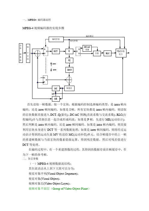
一、MPEG4 编码器流程MPEG-4视频编码器的实现步骤首先读取一帧数据,取一个宏块,根据编码控制选择编码类型,是intra 帧内编码,还是inter 帧间编码。
如果是I 帧,所有宏块都是intra 帧内编码,则读取的宏块数据直接进入DCT 、Q(量化)、DC/AC 预测(直流系数与交流系数)、RLC(行程编码)并与其他信息一起合成形成码流;如果是P 帧,先进行ME(运动估计),然后判断是intra 帧内编码,还是inter 帧间编码。
如果是intra 帧内编码,则直接利用宏块本身进行DCT 等一系列数据处理;如果是inter 帧间编码,则将经过运动估计得到的运动矢量MV 传送给MC(运动补偿)单元,结合帧缓存中的上一帧的重建帧数据与当前宏块的像素值做运算,得到残差数据,然后对残差值进行DCT 等处理。
在编码过程中,有一个重建图像的过程,其得到的数据存放在帧缓存中,作为下一帧的参考帧。
二、各层参数(一)MPEG-4视频数据流结构:其位流语法从上到下大致可以分为:视觉对象序列(Visual Object Sequence),视觉对象(Visual Object),视频对象层(Video Object Layer),视频对象平面层(Group of Video Object Plane ) 帧缓存VLC 多路复合编码控制MVME MCDCT Q IQIDCTRLC intrainter 编码模式量化参数DC/AC 预测扫描取一个宏块读取一帧数据视频对象平面(Video Object Plane)。
VS(Visual Object Sequence):由一系列VO视频对象组成。
场景是一个或多个声视频对象的组合。
场景的逻辑结构可以用一棵树表示,树中的节点是声视频对象。
MPEG4系统用二进制场景格式BIFS描述场景中声视频对象的空间和时间位置及它们之间的关系。
MPEG4的视频比特流提供了对场景的分层描述。
DatasheetAXIS M7104Video EncoderCost-effective,4-channel video encoder with ZipstreamAXIS M7104is a cost-effective,4-channel video encoder that adds the benefits of IP surveillance to an analog camera system.It supports standard-resolution analog cameras as well as PTZ control over RS-485/422.The encoder features a memory card slot for edge storage and support for intelligent analytics such as motion detection and active tampering alarm.Enhanced security features such as signed firmware and secure boot ensure the integrity and authenticity of the encoder’s firmware.Plus,Zipstream with support for H.264/H.265video compression significantly reduces bandwidth and storage requirements.>Full frame rate in all resolutions>Zipstream with support for H.264/H.265>Signed firmware and secure boot>Extended capacity for analytics>PoE and PTZ supportAXIS M7104Video EncoderSystem on chip(SoC)Model ARTPEC-7Memory1024MB RAM,512MB FlashBattery backed-up real-time clockVideoVideo compression H.264(MPEG-4Part10/AVC)Baseline,Main and High Profiles H.265(MPEG-H Part2/HEVC)Main ProfileMotion JPEGResolution176x144/176x120(PAL/NTSC)to720x576/720x480(PAL/NTSC) Frame rate25/30fps in all resolutionsUp to30fps in quad view in full resolutionVideo streaming Multiple,individually configurable streams in H.264,H.265andMotion JPEGAxis Zipstream technology in H.264and H.265Controllable frame rate and bandwidthVBR/MBR H.264/H.265Quad viewImage settings Compression,color,brightness,contrast,rotation:0°,90°,180°, 270°,aspect ratio correction,mirroring of images,text andimage overlay,privacy mask,enhanced deinterlace filter,videotermination,anti-aliasing,sharpness,noise reduction,localenhancementPan/Tilt/Zoom Wide range of analog PTZ cameras supported,drivers included in the firmwareUp to100preset positions/camera,Guard tour,PTZ control queueSupports Windows compatible joysticksNetworkIP address One IP address for four channelsSecurity IP address filtering,HTTPS a encryption,IEEE802.1X a networkaccess control,user access log,centralized certificatemanagementNetwork protocols IPv4,IPv6USGv6,ICMPv4/ICMPv6,HTTP,HTTPS a,TLS a,QoS Layer 3DiffServ,FTP,SFTP,CIFS/SMB,SMTP,mDNS(Bonjour),UPnP®, SNMP v1/v2c/v3(MIB-II),DNS/DNSv6,DDNS,NTP,NTS,RTSP, RTP,SRTP/RTSPS,TCP,UDP,IGMPv1/v2/v3,RTCP,ICMP,DHCP, ARP,SSHSystem integrationApplication Programming Interface Open API for software integration,including VAPIX®and AXIS Camera Application Platform;specifications at AXIS Video Hosting System(AVHS)with One-Click Camera ConnectionOne-click cloud connectionONVIF®Profile G,ONVIF®Profile M,ONVIF®Profile S and ONVIF®Profile T,specification at Event triggers Analytics,video loss,edge storage eventsMQTT subscribeEvent actions File upload:FTP,SFTP,HTTP,HTTPS network share and emailNotification:email,HTTP,HTTPS and TCPExternal output activationMQTT publishPre-and post-alarm video bufferingPTZ presetStatus LEDData streaming Event dataAnalyticsApplications IncludedAXIS Motion Guard,AXIS Fence Guard,AXIS Loitering GuardAXIS Video Motion Detection,active tampering alarmSupportedSupport for AXIS Camera Application Platform enablinginstallation of third-party applications,see /acap CybersecurityEdge security Software:Signed firmware,brute force delay protection,digest authentication,password protection,AES-XTS-Plain64256bitSD card encryptionHardware:Secure bootNetwork security IEEE802.1X(EAP-TLS)a,IEEE802.1AR,HTTPS/HSTS a,TLSv1.2/v1.3a,Network Time Security(NTS),X.509Certificate PKI,IP address filteringDocumentation AXIS OS Hardening GuideAxis Vulnerability Management PolicyAxis Security Development ModelTo download documents,go to /support/cybersecu-rity/resourcesTo read more about Axis cybersecurity support,go to/cybersecurityGeneralCasing Stand alone,metal casing,wall mountSustainability PVC freePower8-28V DC,max4.7WPower over Ethernet(PoE)IEEE802.3af/802.3at Type1Class3 Connectors Four analog composite video BNC inputRJ4510BASE-T/100BASE-T/1000BASE-T PoERS485/RS422,2pcs,2pos,full duplex,terminal block Storage Support for microSD/microSDHC/microSDXC cardSupport for SD card encryption(AES-XTS-Plain64256bit)Support for recording to network-attached storage(NAS)For SD card and NAS recommendations see Operatingconditions0°C to50°C(32°F to122°F)Humidity10-85%RH(non-condensing)Storageconditions-40°C to65°C(-40°F to149°F)Humidity5-95%RH(non condensing)Approvals EMCEN55032Class A,EN61000-3-2,EN61000-3-3,EN55024,EN61000-6-1,EN61000-6-2,FCC Part15Subpart B Class A,ICES-003Class A,VCCI Class A,RCM AS/NZS CISPR32Class A,KC KN32Class A,KC KN35SafetyIEC/EN/UL62368-1EnvironmentIEC60068-2-1,IEC60068-2-2,IEC60068-2-6,IEC60068-2-14,IEC60068-2-27,IEC60068-2-78NetworkNIST SP500-267Dimensions187x37mm(7.4x1.5in)Weight650g(1.4lb)IncludedaccessoriesInstallation guide,Windows®decoder1-user license,DC inputplug,2pcs2-pin RS485/RS422plugsOptionalaccessoriesFor more accessories,see VideomanagementsoftwareAXIS Companion,AXIS Camera Station,Video managementsoftware from Axis Application Development Partners availableat /vmsLanguages English,German,French,Spanish,Italian,Russian,SimplifiedChinese,Japanese,Korean,Portuguese,Traditional Chinese Warranty Axis3-year warranty,see /warrantya.This product includes software developed by the OpenSSL Project for use in the OpenSSL Toolkit.(),and cryptographic software written by Eric Young (*****************).Environmental responsibility:/environmental-responsibility©2019-2023Axis Communications AB.AXIS COMMUNICATIONS,AXIS,ARTPEC and VAPIX are registered trademarks ofAxis AB in various jurisdictions.All other trademarks are the property of their respective owners.We reserve the right tointroduce modifications without notice.T10137686/EN/M20.8/2301。
安装指南Avigilon™模拟视频编码器型号:ENC-4P-H264重要安全信息本手册针对本摄像机的使用提供有关安装与操作信息以及预防措施。
安装不当可能导致意外故障。
安装本设备之前,请仔细阅读本手册。
请为设备用户提供本手册,以备日后使用。
l请勿靠近水使用或受到淋湿或溅湿。
l请勿将装有液体的物品放置在设备的上方。
l请勿受雨淋或受潮。
l仅限室内使用。
如果在室外使用,则需要使用规定的室外安装转换器或防护罩。
如需更多信息,请咨询Avigilon。
l安装设备仅限合格人员来完成,且必须符合当地所有法规。
l本产品专用电源为标有“2级”或“LPS”或“有限功率电源”的UL认证电源单元,额定输出电压为12 VDC或24 VAC,最小额定功率为8 W;或者,采用以太网供电(PoE),额定电压为48 VDC,最小额定功率为8 W。
l与本产品连接的任何外部电源只能与同型号系列的其他Avigilon产品连接。
外部电源接头必须进行适当绝缘。
l严禁与市供电源直接连接。
l请勿安装在任何热源附近,比如散热器、热风口、炉灶或其他热源。
l请勿使线缆受到过大压力、过重负载或拧扯。
l请勿拆开或拆解设备。
产品不含用户可自行维修部件。
l将所有维修交给合格人员完成。
可能需要维修的情况有以下几种:摄像机损坏(比如,因液体溅湿或坠落物而损坏),受雨淋或受潮,不正常运行或者掉落。
l清洁设备机身时,请勿使用强效洗涤剂或腐蚀性洗涤剂。
l仅使用Avigilon推荐的附件。
l如果未按照本文档的说明来使用控制或调节装置或者操作步骤,可能会导致有害辐射泄露。
合规声明本设备符合FCC规程的第15部分规定。
摄像机运行遵守以下两个条件:(1)本设备不会产生有害干扰;(2)本设备必须承受收到的任何干扰,包括可能导致意外运行的干扰。
本A类数码设备符合加拿大ICES-003标准。
FCC声明测试结果表明,根据FCC规程第15部分,本设备符合A类数码设备的规定。
这些规定用于提供合理保护,以免在商业环境中运行时受到有害干扰。