Distributed-Temperature-Sensor多路温度传感器大学毕业论文外文文献翻译及原文
- 格式:doc
- 大小:283.50 KB
- 文档页数:19
Met One Instruments, IncCorporate Sales & Service: 1600 NW Washington Blvd. Grants Pass, OR 97526 Tel (541) 471-7111 Fax (541) 471-7116 **********************MODEL T-200PLATINUM RESISTANCE TEMPERATURE SENSOROPERATION MANUALCopyright NoticeT-200-9800 OPERATION MANUAL© Copyright 2001 Met One Instruments, Inc. All Rights Reserved Worldwide. No part of this publication may be reproduced, transmitted, transcribed, stored in a retrieval system, or translated into any other language in any form by any means without the express written permission of Met One Instruments, Inc.Technical SupportShould you require support, please consult your printed documentation to resolve your problem. If you are still experiencing difficulty, you may contact a Technical Service representative during normal business hours—7:00 a.m. to 4:00 p.m. Pacific Time, Monday through Friday.Voice: (541) 471-7111Fax: (541) 471-7116E-Mail: ******************Mail: Technical Services DepartmentMet One Instruments, Inc.1600 NW Washington BlvdGrants Pass, OR 97526T-200 PLATINUM RESISTANCE TEMPERATURE SENSOROPERATION MANUALCONTENTSPage1. Specifications 42. Installation in Power Aspirated Shield (PN 327C or 076B) 63. Installation in Wind Aspirated Shield (PN 073B or 5980) 64. Sensor Connections 7ILLUSTRATIONSFigure1 Platinum Resistance Temperature Sensor Dimensions 52. Terminal Board Identification for Connection of RTD toProcessor Mounted in 49.03 Rack Mount 83. RTD Schematics 9TABLESTable1 Typical Sensor Formulas 102. Typical Computed Values, Celsius 113. Typical Computed Values, Fahrenheit 12PLATINUM RESISTANCE TEMPERATURE SENSOR1.0 SPECIFICATIONSResistance Element PlatinumNominal Resistance R o = 100 ± 0.1ΩSensitivity α = 0.00385 ± 0.00002 Ω/Ω/︒COperating Range -50︒C to +100︒COperating Environment Atmospheric air temperature (sheltered fromnormal precipitation)Time constant Less than 10 seconds in well stirred water bathTime Stability Temperatures, as computed from the probecalibration data, must be within ±0.05︒C over aone-year period from the time of calibration Sensor Sheath Type 300 series stainless steelLead WiresNumber FourGauge # 22Material Standard CopperPlating OptionalInsulation TeflonDimensions See FIGURE 12.0 INSTALLATION IN POWER ASPIRATED SHIELDS2.1 To mount the sensor, assemble retaining bracket for selected sensor to mount onmounting butts located in the neck of shield assembly. The supplied clip assemblyshould only be used for sensors with a nominal cross-sectional diameter of 0.25 inch.Attach sensor and install in sensor cavity.2.2 When used in the Model 327C Motor Aspirated Temperature Shield, a cable partnumber 1734 will be required to connect to the sensor, See FIGURE 3CAUTIONLower tip of sensor must not fall lower than 3 ¼ inches from under side of umbrellashield. If sensor tip falls below this point, remount. Failure to do so may result intemperature reading errors exceeding specifications during periods of maximum solarradiation.2.3 Thread the sensor leads through the air duct assembly and out from the grommetlocated on the underside of the tube. Mount the triple shield assembly to the air ductassembly.2.4 For additional information, see Manual 327C.2.5 When used in the Power Aspirated Shield Model 076B, the 1734 cable is not requiredand the sensor is connected directly to the terminal block inside the internal junction box of the 076B Shield.2.6 The temperature sensor is held in place by the two nylon ¼” sensor holders in thecenter tube of the removable lower section of the 076B Power Aspirated Shield. Insert the sensor down into the center section. The sensor should not touch the bottom of the shield but should be about 2 inch above the bottom plate in the shield center section. 2.7 For additional information, see Manual 076B3.0 INSTALLATION IN WIND ASPIRATED SHIELD3.1 The sensor units are precision instruments sturdily constructed for worst-caseenvironmental abuse, but careful handling should be observed when unpacking andinstalling so as not to cause damage that may degrade their performance.3.2 Using the adapter plate part number 10418, the T-200 Sensor can be used in both theModel 5980 and Model 073B Wind Aspirated Temperature Shields.3.3 The temperature probe should first be inserted through the rubber seal in the cord gripfitting of the 10418 Adapter Plate. It should extend approximately 2” above the plate.Once set to the correct position, the collar of the cord grip fitting can be tightened tosecure the probe in the collar.3.4 For additional information, see Manuals 073B or 59804.0 SENSOR CONNECTIONS4.1 Care must be exercised when installing the RTD and connecting it to the processor.Because of the low level signals (i.e. 4 μ V = 0.01︒C) being processed, errors can beinduced by noisy connectors, thermally induced junction voltages, and FRI generatedvoltages.4.2 Low thermal solder should be used to make signal wire (two per RTD) connections ifthere is a possibility of the junctions being at different temperatures. Where pre-tinned wire is used, the wire should be stripped or scraped to the copper before using lowthermal solder.4.3 Proper signal polarity must be observed when connecting RTDs to the Met OneInstruments 21.32 or 21.43 Processors. FIGURE 2 indicates polarity designations and gives pin assignments to be followed. FIGURE 3 gives the RTD schematics.4.4 When connecting to data logger or other devices, this polarity should also be maintainedto insure accurate measurement from the sensor.4.5 The typical connections to be made are l+ and l- to drive the RTD, and E+ and E- tobring the signal back to the processor. l+ and E+ and l- and E- are normally tiedtogether within the RTD probe as close to the actual platinum sensor as possible. Noother connection between the two wires should be made.RTD SCHEMATICSTABLE 1TYPICAL SENSOR FORMULASR P = R O * (1 + α * T + K + L)K = α * δ * (T/100) * (1 – T/100)L = α * β * (T/100) * (T/100) * (T/100) * (1 – T/100)R P = Sensor Resistance at temperature TT = Temperature in CelsiusR O = Sensor resistance at 0︒ Celsius, 100α = Nominal sensitivity, 0.00385δ = Nonlinearity, α * δ = 0.00580195β = Low temperature correction,α * β = 0, temperature above 0︒ Celsiusα * β = 0.00042735, temperature below 0︒ CelsiusTYPICAL COMPUTED VALUES, CELSIUSPROGRAM IECRVST/BASRO = 100 ALPHA= 3.85 E-3DELTA = 1.507 BETA = 0.111Temperature Resistance Temperature Resistance Temperature Resistance Centigrade Ohms Centigrade Ohms Centigrade Ohms -50 80.307 0 100.000 50 119.395 -49 80.704 1 100.391 51 119.780 -48 81.101 2 100.781 52 120.165 -47 81.498 3 101.172 53 120.550 -46 81.894 4 101.562 54 120.934 -45 82.291 5 101.953 55 121.319 -44 82.687 6 102.343 56 121.703 -43 83.083 7 102.733 57 122.087 -42 83.479 8 103.123 58 122.471 -41 83.875 9 103.513 59 122.855 -40 84.271 10 103.902 60 123.239 -39 84.667 11 104.292 61 123.623 -38 85.063 12 104.681 62 124.007 -37 85.458 13 105.071 63 124.390 -36 85.853 14 105.460 64 124.774 -35 86.248 15 105.849 65 125.157 -34 86.643 16 106.238 66 125.540 -33 87.038 17 106.627 67 125.923 -32 87.433 18 107.016 68 126.306 -31 87.828 19 107.404 69 126.689 -30 88.222 20 107.793 70 127.072 -29 88.617 21 108.181 71 127.454 -28 89.011 22 108.570 72 127.837 -27 89.405 23 108.958 73 129.219 -26 89.799 24 109.346 74 128.602 -25 90.193 25 109.734 75 128.984 -24 90.587 26 110.122 76 129.366 -23 90.980 27 110.509 77 129.748 -22 91.374 28 110.897 78 130.130 -21 91.767 29 111.284 79 130.511 -20 92.160 30 111.672 80 130.893 -19 92.553 31 112.059 81 131.274 -18 92.946 32 112.446 82 131.656 -17 93.339 33 112.833 83 132.037 -16 93.732 34 113.220 84 132.418 -15 94.125 35 113.607 85 132.799 -14 94.517 36 113.994 86 133.180 -13 94.910 37 114.380 87 133.561 -12 95.302 38 114.767 88 133.941 -11 95.694 39 115.153 89 134.322 -10 96.086 40 115.539 90 134.702 -9 96.478 41 115.925 91 135.083 -8 96.870 42 116.311 92 135.463 -7 97.262 43 116.697 93 135.843 -6 97.653 44 117.083 94 136.223 -5 98.045 45 117.469 95 136.603 -4 98.436 46 117.854 96 136.982 -3 98.827 47 118.240 97 137.362 -2 99.218 48 118.625 98 137.741 -1 99.609 49 119.010 99 138.1210 100.000 50 119.395 100 138.500TYPICAL COMPUTED VALUES, FAHRENHEITPROGRAM IECRVST/BASRO = 100 ALPHA= 3.85E-3DELTA = 1.507 BETA = 0.111Temperature Resistance Temperature Resistance Temperature Resistance Fahrenheit Ohms Fahrenheit Ohms Fahrenheit Ohms -70 77.656 30 99.566 130 121.105 -68 78.098 32 100.000 132 121.532 -66 78.540 34 100.434 134 121.959 -64 78.982 36 100.868 136 122.386 -62 79.424 38 101.302 138 122.813 -60 79.865 40 101.716 140 123.239 -58 80.307 42 102.169 142 123.666 -56 80.748 44 102.603 144 124.092 -54 81.189 46 103.036 146 124.518 -52 81.630 48 103.469 148 124.944 -50 82.071 50 103.902 150 125.370 -48 82.511 52 104.335 152 125.796 -46 82.951 54 104.768 154 126.221 -44 83.391 56 105.200 156 126.647 -42 83.831 58 105.633 158 127.072 -40 84.271 60 106.065 160 127.497 -38 84.711 62 106.497 162 127.922 -36 85.150 64 106.929 164 128.347 -34 85.590 66 107.361 166 128.771 -32 86.029 68 107.793 168 129.196 -30 86.468 70 108.224 170 129.620 -28 86.907 72 108.656 172 130.045 -26 87.345 74 109.087 174 130.469 -24 87.784 76 109.518 176 130.893 -22 88.222 78 109.949 178 131.317 -20 88.660 80 110.380 180 131.740 -18 89.098 82 110.811 182 132.164 -16 89.536 84 111.241 184 132.587 -14 89.974 86 111.672 186 133.011 -12 90.412 88 112.102 188 133.434 -10 90.849 90 112.532 190 133.857 -8 91.286 92 112.962 192 134.280 -6 91.723 94 113.392 194 134.702 -4 92.160 96 113.822 196 135.125 -2 92.597 98 114.251 198 135.5470 93.034 100 114.681 200 135.9692 93.470 102 115.110 202 136.3924 93.907 104 115.539 204 136.8146 94.343 106 115.968 206 137.2358 94.779 108 116.397 208 137.65710 95.215 110 116.826 210 138.07912 95.651 112 117.254 212 138.50014 96.086 114 117.683 214 138.92116 96.522 116 118.111 216 139.34218 96.957 118 118.539 218 139.76320 97.392 120 118.967 220 140.18422 97.827 122 119.395 222 140.60524 98.262 124 119.823 224 141.02526 98.697 126 120.250 226 141.44628 99.131 128 120.678 228 141.86630 99.566 130 121.105 230 142.286。
. sensorssensors(English name: transducer/sensor) is a kind of detection device, can feel the measured information, and will feel information transformation according to certain rule become electrical signal output, or other form of information needed to satisfy the information transmission, processing, storage, display, record and control requirements.Sensor's features include: miniaturization, digital, intelligent, multi-functional, systematic and network. It is the first step of automatic detection and automatic control. The existence and development of the sensor, let objects have sensory, such as touch, taste and smell let objects become live up slowly. Usually according to its basic cognitive functions are divided into temperature sensor, light sensor, gas sensor, force sensor, magnetic sensor, moisture sensor, acoustic sensor, radiation sensitive element, color sensor and sensor etc. 10 major categories.temperature transducerTemperature sensors (temperature transducer) refers to can feel temperature translates into usable output signal of the sensor. The temperature sensor is the core part of the temperature measuring instrument, wide variety. According to measuring methods could be divided into two types: contact and non-contact, according to the sensor material and electronic component features divided into two categories, thermal resistance and thermocouple.1 principle of thermocoupleThermocouple is composed of two different materials of metal wire, the welded together at the end. To measure the heating part of the environment temperature, can accurately know the temperature of the hot spots. Because it must have two different material of the conductor, so called the thermocouple. Different material to make the thermocouple used in different temperature range, their sensitivity is also each are not identical. The sensitivity of thermocouple refers to add 1 ℃hot spot temperature changes, the output variation of potential difference. For most of the metal material support thermocouple, this value about between 5 ~ 40 microvolt / ℃.As a result of the thermocouple temperature sensor sensitivity has nothing to do with the thickness of material, use very fine material also can make the temperature sensor. Also due to the production of thermocouple metal materials have good ductility, the slight temperature measuring element has high response speed, can measure the process of rapid change.Its advantages are:(1)high precision measurement. Because of thermocouple direct contact with the object being measured, not affected by intermediate medium.(2)the measurement range. Commonly used thermocouple from 1600 ℃to 50 ℃ ~ + sustainable measurement, some special thermocouple minimum measurable to - 269 ℃ (e.g., gold iron nickel chrome), the highest measurable to + 2800 ℃ (such as tungsten rhenium).(3) simple structure, easy to use. Thermocouple is usually composed of two different kinds of metal wire, but is not limited by the size and the beginning of, outside has protective casing, so very convenient to use. The thermocouple type and structure of the form.2. The thermocouple type and structure formation(1)the types of thermocoupleThe commonly used thermocouple could be divided into two types: standard thermocouple and non-standard thermocouple. Standard thermocouple refers to the national standard specifies its thermoelectric potential and the relationship between temperature, permissible error, and a unified standard score table of thermocouple, it has with matching display instrument to choose from. Rather than a standard thermocouple or on the order of magnitude less than the range to use standardized thermocouple, in general, there is no uniform standard, it is mainly used for measurement of some special occasions.Standardized thermocouple is our country from January 1, 1988, thermocouple and thermal resistance of all production according to IEC international standard, and specify the S, B, E, K, R, J, T seven standardization thermocouple type thermocouple for our country unified design.(2)to ensure that the thermocouple is reliable, steady work, the structure of thermocouple requirements are as follows:①of the two thermocouple thermal electrode welding must be strong;②two hot electrode should be well insulated between each other, in case of short circuit;③compensation wires connected to the free cod of a thermocouple to convenient and reliable;④protect casing thermal electrodes should be able to make sufficient isolation and harmful medium.3.The thermocouple cold end temperature compensationDue to the thermocouple materials are generally more expensive (especiallywhen using precious metals), and the temperature measurement points are generally more far, the distance to the instrument in order to save materials, reduce cost, usually adopt the compensating conductor) (the free end of the cold junction of the thermocouple to the steady control of indoor temperature, connected to the meter terminals. It must be pointed out that the role of the thermocouple compensation wire extension hot electrode, so that only moved to the control room of the cold junction of the thermocouple instrument on the terminal, it itself does not eliminate the cold end temperature change on the influence of temperature, cannot have the compensation effect. So, still need to take some of the other correction method to compensate of the cold end temperature especially when t0 indicates influence on measuring temperature 0 ℃.Must pay attention to when using thermocouple compensating conductor model match, cannot be wrong polarity, compensation conductor should be connected to the thermocouple temperature should not exceed 100 ℃.传感器传感器(英文名称:transducer/sensor)是一种检测装置,能感受到被测量的信息,并能将感受到的信息,按一定规律变换成为电信号或其他所需形式的信息输出,以满足信息的传输、处理、存储、显示、记录和控制等要求。
露点温度传感器发展趋势综述聂晶,刘曦(北京航空航天大学仪器科学与光电工程学院,北京 100191)摘要:介绍了目前露点温度传感器领域的研究现状,阐述了光学式、谐振式、电学式、热学式、重量式、化学式露点温度传感器的原理及构造,指出光学式露点温度传感器测量精度极高,其中冷镜式露点仪可作为湿度计量标准;谐振式露点温度传感器具有体积小、成本低、响应时间短、灵敏度高、可靠性好的特点;电学式露点温度传感器灵敏度高、功耗小,便于实现小型化、集成化;重量法是准确度最高的湿度绝对测量方法;化学法常用来测量低湿环境下的有机混合气体。
探讨了露点温度传感器在环境监测、工业制造、医疗诊断等领域的应用情况,指出未来露点温度传感器将会向高精度、高稳定性、高响应的方向发展,且应用范围将进一步拓展,以满足极端环境下的测量需求。
关键词:湿度测量;露点温度传感器;湿度传感器中图分类号:TB94;TP212 文献标志码:A 文章编号:1674-5795(2024)01-0043-17Review of the development trends of dew point temperature sensorsNIE Jing, LIU Xi(School of Instrumentation and Optoelectronic Engineering, Beihang University, Beijing 100191, China) Abstract: Introducing the current research status in the field of dew‐point temperature sensors, and expounding the principles and structures of optical, resonant, electrical, thermal, weight and chemical dew‐point temperature sensors. It is pointed out that the optical dew point temperature sensor has high measurement accuracy, and the cold mirror dew point sensor can be used as the humidity measurement standard. The resonant dew point temperature sensor has the characteris‐tics of small size, low cost, short response time, high sensitivity and good reliability. The electrical dew point temperature sensor has high sensitivity and low power consumption, which is convenient for miniaturization and integration. Gravimetric method is the most accurate absolute humidity measurement method and the basis for establishing humidity benchmark. Chemical methods are often used to measure organic gas mixtures in low humidity. The application of dew point tempera‐ture sensor in environmental monitoring, industrial manufacturing, medical diagnosis and other fields is discussed. It is pointed out that dew point temperature sensors will develop towards high precision, high stability and high response in the future, and their application range will be further expanded to meet the measurement needs in extreme environments.Key words: humidity measurement; dew point temperature sensor; humidity sensor0 引言湿度表示大气中水汽含量的多少,即大气的干、湿程度。
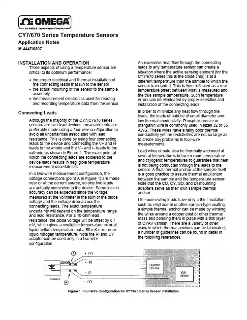
CY7/670 Series Temperature SensorsApplication NotesM-4447/0307INSTALLATION AND OPERATIONThree aspects of using a temperature sensor are critical to its optimum performance:• the proper electrical and thermal installation of the connecting leads that run to the sensor• the actual mounting of the sensor to the sample assembly• the measurement electronics used for reading and recording temperature data from the sensorConnecting LeadsAlthough the majority of the CY7/CY670 series sensors are two-lead devices, measurements are preferably made using a four-wire configuration to avoid all uncertainties associated with leadresistance. This is done by using four connecting leads to the device and connecting the V+ and I+ leads to the anode and the V– and I– leads to the cathode as shown in Figure 1. The exact point at which the connecting leads are soldered to the device leads results in negligible temperature measurement uncertainties.In a two-wire measurement configuration, thevoltage connections (point A in Figure 1) are made near or at the current source, so only two leads are actually connected to the device. Some loss in accuracy can be expected since the voltagemeasured at the voltmeter is the sum of the diode voltage and the voltage drop across the connecting leads. The exact temperatureuncertainty will depend on the temperature range and lead resistance. For a 10-ohm leadresistance, the diode voltage will be offset by 0.1 mV, which gives a negligible temperature error at liquid helium temperature but a 50 mK error near liquid nitrogen temperature. Note the PI and CY adapter can be used only in a two-wire configuration.An excessive heat flow through the connecting leads to any temperature sensor can create asituation where the active sensing element (for the CY7/670 series this is the diode chip) is at adifferent temperature than the sample to which the sensor is mounted. This is then reflected as a real temperature offset between what is measured and the true sample temperature. Such temperature errors can be eliminated by proper selection and installation of the connecting leads.In order to minimize any heat flow through the leads, the leads should be of small diameter and low thermal conductivity. Phosphor-bronze ormanganin wire is commonly used in sizes 32 or 36 AWG. These wires have a fairly poor thermalconductivity yet the resistivities are not so large as to create any problems in four-wire measurements.Lead wires should also be thermally anchored at several temperatures between room temperature and cryogenic temperatures to guarantee that heat is not being conducted through the leads to the sensor. A final thermal anchor at the sample itself is a good practice to assure thermal equilibrium between the sample and the temperature sensor. Note that the CU, CY, SO, and DI mounting adapters serve as their own sample thermal anchor.I the connecting leads have only a thin insulation such as vinyl acetal or other varnish type coating, a simple thermal anchor can be made by winding the wires around a copper post or other thermal mass and bonding them in place with a thin layer of CYAV varnish. There are a variety of other ways in which thermal anchors can be fabricated; a number of guidelines can be found in detail inthe following references.Figure 1. Four-Wire Configuration for CY7/670 Series Sensor InstallationSensor MountingGeneral CommentsBefore installing the CY7/670 series sensor,identify which lead is the anode and which lead isthe cathode by referring to the accompanyingdevice drawings. Be sure that lead identificationremains clear even after installation of the sensor,and record the serial number and location.The procedure used to solder the connectingleads is not very critical and there is very littledanger in overheating the sensor. If for somereason the leads need to be cut short, they shouldbe heat sunk with a copper clip or needle-nosepliers before soldering. Standard rosin-coreelectronic solder (m.p. 180C) is suitable for mostapplications. Applications involving the use of theSD package up to 200 °C require a higher meltingpoint solder. A 90% Pb 10% Sn solder has beenused quite successfully with a rosin flux.For all adapters except the CY, CU, and DI, theleads are gold-plated Kovar. Prolonged solderingtimes may cause the solder to creep up the gold-plated leads as the solder and the gold alloy. Thisis not detrimental to the device performance.When installing the sensor:• Make sure there are no shorts or leakageresistance between the leads or between theleads and ground. CYAV varnish or epoxy maysoften varnish-type insulations so that highresistance shunts appear between wires ifsufficient time for curing is not allowed. Teflonspaghetti tubing is useful for sliding over bareleads when the possibility of shorting exists.• Avoid putting stress on the device leads andallow for the contractions that occur duringcooling that could fracture a solder joint or lead ifinstalled under tension at room temperature.The CY7/670 series sensor is designed for easyremoval for recalibration checks or replacement,and the following discussions for each of theadapters are geared in this direction. If semi-permanent mountings are desired, the use of OB-CY10 or OB-CY20 low temperature epoxy canreplace the use of CYAG grease. In all cases, themounting of the sensor should be periodicallyinspected to verify that good thermal contact to themounting surface is maintained.CY7/670-SDThe SD version is the basic package for theCY7/670 series sensor line, from which all otherconfigurations are made using the appropriateadapter. The base of the device has a goldmetallized surface and is the largest flat surfaceon the sensor. The base is electrically isolatedfrom the sensing element and leads, and allthermal contact to the sensor must be madethrough the base. A thin braze joint around the sides of the SD package is electrically connected to the sensing element. Contact to the sides with any electrically conductive material must be avoided. When viewed base down and with leads towards the observer, the positive lead (anode) is on the right. For a removable mount, the SD sensor can be held against the mounting surface with the CO adapter (see below) or similar clamping mechanism. Any method of clamping the sensor must avoid excessive pressure and should be designed so that thermal contractions or expansions do not loosen contact with the sensor. For uses restricted to below 325 K, a thin layer of CYAG grease should be used between the sensor and sample to enhance thermal contact.The SD package can also be bonded with a low temperature epoxy. The sensor should be pressed firmly against the surface during curing to assure a thin epoxy layer and a good thermal contact. The device may be removed in the future by using the appropriate epoxy stripper.The SD adapter can be soldered using a rosin flux (non-corrosive) if extreme care is exercised.1. Tin the base of the sensor using a lowwattage, temperature controlled soldering iron that will not exceed 200 °C. Use only aminimal amount of solder. Tin the surface towhich the sensor is to be bonded and again,avoid an excessive thickness of solder. Clean both the sensor and the mounting surface ofany residual flux.2. Reheat the mounting surface to the meltingpoint of the solder, press the device intoposition and allow the sensor to warm to themelting point of the solder.3. After both tinned surfaces have flowedtogether, remove the heat source and let thesample and sensor cool.Under no circumstance should the sensor be heated above 200 °C and the solder must be limited to only the base of the sensor. Excess solder running up the sides of the SD package can create shorts. Repeated mounting and demounting of a soldered sensor may eventually cause wetting deterioration and ruin the thermal contact to the sensing element, although the nickel buffer layer should minimize these problems.CAUTIONThe preferred method for mounting the SD sensor is either the CO adapter or bonding with epoxy. Omega Engineering, Inc. will not warranty replace any device damaged by a user-designed clamp or damaged through solder mounting.2CY7/670-LRThe gold-coated copper LR adapter is designedfor insertion into a 1/8-inch diameter tube. A thinlayer of CYAG grease should be applied to thecopper adapter before insertion. This easesinstallation at room temperature and enhances thethermal contact.CY7/670-CU/DI/CYThe gold-coated copper CU, DI and CY adaptersserve as both a sensor and a thermal anchorassembly. These adapters are designed to bemounted to a flat surface using a 4-40 brassscrew. Avoid over-tightening the screw; use onlyenough force to firmly hold the sensor in place.Brass is recommended for the screw as thedifferential thermal contraction between theadapter and the screw will cause the mountingassembly to tighten as opposed to loosen whenthe system is cooled. A thin layer of CYAG greaseshould be used to enhance the thermal contactbetween the adapter and the mounting surface.The CU adapter has four color-coded leads: red(I–), green (V–), clear (V+), and blue (I+). The CYadapter has two color-coded leads: yellow (+) andgreen (–). The green lead on the DI adapter is thecathode.CY7/670-ET/MTBoth adapters are gold-plated copper hex headbolts with the SD package mounted in a slot onthe adapter head. The ET adapter screws into a ¼inch deep, 6-32 threaded hole while the MTadapter screws into a 6 mm deep, 3 × 0.5 mmthreaded hole. Before assembly, the threadsshould be lightly greased with CYAG grease. Donot over-tighten, since the threads are copper andcan be easily sheared. Finger-tight should besufficient.CY7/670-BOThe BO adapter should be mounted in the samemanner as the CU. The BO adapter contains itsown thermal anchor and is an epoxy-freeassembly.CY7/670-COThe CO adapter is used to attach the CY7/670-SDpackage to a flat surface. The adapter is a spring-loaded clamp designed to maintain pressure onthe SD package as the temperature is varied.1. Remove the hold down cap that holds thethree-piece CO assembly together. The COassembly should appear as shown in theaccompanying drawings.2. Bolt the assembly into a 4-40 threaded hole.The stop on the brass screw should restagainst the mounting surface and it alsoprevents overcompressing the spring.3. Lift the edge of the clip using a small pair ofpliers or screwdriver.4. Slide the SD package into place underneaththe clip and gently lower the clip onto the lid ofthe SD package. Note that a slot is cutunderneath the clip to accept the SD package.Refer to the drawing for details.If the device is to be used only below 325 K, alayer of CYAG grease should be used betweenthe SD package and mounting surface to enhancethe thermal contact.Sensor OperationTemperature controllers and thermometerinstrumentation offered by Omega Engineering,Inc. are designed to be directly compatible with theCY7/670 series sensor to give optimumperformance and accuracy together with directtemperature readouts. Simply follow theinstructions provided with the instrumentconcerning sensor connection and instrumentoperation. If a user-supplied current source,voltmeter, or other instrumentation is going to beused with the CY7/670 series sensor, specialattention should be given to the following details.The CY7/670 series sensors are designed tooperate at a constant current of 10 µA while thevoltage variation with temperature measurementdepends directly on the specifications of thecurrent source and the voltmeter. A current sourceoperating at the level of +0.01 µA (±0.01 K) isprobably suitable for most applications. Thevoltmeter resolution required can be estimatedfrom the sensitivity (dV/dT) of the CY7/670 sensor:Temperature Sensitivity(K) (mV/K)305 2.477 1.94.2 33Multiplying the above sensitivity by the desiredtemperature resolution in K will give the requiredvoltage resolution in mV.The static impedance of the CY7/670 seriessensor operating at 10 µA current is on the orderof 100,000 ohms. Therefore, the input impedanceof the voltmeter must be significantly larger thanthis to avoid measurement errors. Voltmeters withinput impedances of greater than 109 or 1010ohms should be used.Good quality instrumentation must be used and allinstrumentation and wiring should be properlygrounded and shielded. Temperaturemeasurement errors will result if there is excessiveAC noise or ripple in the circuitry. Further detailscan be found in the article by Krause and Dodrillgiven in the references.Note: All materials mentioned above that are usedin sensor installation are available from OMEGAEngineering, Inc.3REFERENCESKrause, J.K. and Swinehart, P.R. (1985). Demystifying Cryogenic Temperature Sensors. Photonics Spectra. August, 61–68. Krause, J.K. and Dodrill, B.C. (1986). Measurement System Induced Errors in Diode Thermometry. Review of Scientific Instruments 57 (4), 661–665.Sparks, L.L. (1983). Temperature, Strain, and Magnetic Field Measurements. In Material at Low Temperatures, Ed. By R.P. Reed and A.F. Clark. American Society of Metals, Metals Park, 515–571.White, G.K. (1979). Experimental Techniques in Low Temperature Physics. Clarendon Press, Oxford.CY7/670-SDBasic sensor package style.Temperature range: 1.4 to 475 KMass: 0.03 gCY7/670-ETBasic sensor soldered onto SAE-threaded copper adapter.Temperature range: 1.4 to 325 KMass: 1.4 gCY7/670-BOBasic sensor soldered onto bolt-oncopper block with leads thermallyanchored to block.Temperature range: 1.4 to 325 KMass: 1.5 gCY7/670-CU/DIBasic sensor mounted intobolt-on disk with leads thermallyanchored to disk with lowtemperature epoxy. CU version is4-lead. DI is 2-lead.Temperature range: 1.4 to 325 KMass (excluding leads): 4.3 g CY7/670-COBasic sensor with spring-loadedbrass clamp to hold sensor tosample.Temperature range: 1.4 to 475 KMass (without sensor): 1.7 gCY7/670-CYBasic sensor epoxied intorelatively large copper disk. 30AWG stranded copper lead pair isthermally anchored to disk.Temperature range: 1.4 to 325 KMass (excluding leads): 4.3 gCY7/670-LRBasic sensor soldered intocylindrical copper adapter.Temperature range: 1.4 to 325 KMass: 0.15 gCY7/670-MTBasic sensor soldered into metric-threaded copper adapter.Temperature range: 1.4 to 325 KMass: 1.4 gServicing USA and Canada:Call OMEGA Toll FreeOMEGA Engineering, Inc.One Omega Drive, Box 4047Stamford, CT 06907-0047 U.S.A.Headquarters: (203) 359-1660Sales: 1-800-826-6342 / 1-800-TC-OMEGACustomer Service: 1-800-622-2378 / 1-800-622-BESTEngineering: 1-800-872-9436 / 1-800-USA-WHENFAX: (203) 359-7700 TELEX: 996404EASYLINK 62968934 CABLE OMEGAServicing Europe: United Kingdom Salesand Distribution CenterOMEGA Technologies Ltd.25 Swannington Road, Broughton Astley, LeicestershireLE9 6TU, EnglandTelephone: 44 (0455) 285520 FAX: 44 (0455) 283912。

OMEGARH62C-MVHumidity Temperature TransducerOMEGAnet On-Line Service Internet e-mail **************For immediate technical or application assistance:USA and Canada:Mexico and Latin America:Sales Service: 1-800-826-6342 / 1-800-TC-OMEGA Tel: (95) 800-TC-OMEGA Customer Service: 1-800-622-2378 / 1-800-622-BEST FAX: (95) 203-359-7807Engineering Service: 1-800-872-9436 / 1-800-USA-WHEN En Español: (203) 359-7803TELEX: 996404 EASYLINK: 62968934 CABLE: OMEGA e-mail:*****************Servicing North America:USA: ISO 9001 Certified Canada:One Omega Drive, Box 4047976 Bergar Stamford, CT 06907-0047Laval (Quebec) H7L5A1Tel: (203) 359-1660Tel: (514) 856-6928FAX: (203)359-7700FAX: (514) 856-6886e-mail:**************e-mail:**************Servicing Europe:Benelux:Postbus 8034, 1180 LA Amstelveen,The Netherlands Tel: (31) 20 6418405 FAX: (31) 20 6434643Toll Free in Benelux: 06 0993344e-mail:************Czech Republic:ul. Rude armady 1868, 733 01 Karvina-Hranice, Czech Repubic Tel: 420 (69) 6311627 FAX: 420 (69)6311114e-mail:***************France:9, rue Denis Papin, 78190 Trappes Tel: (33) 130-621-400 FAX: (33)130-699-120Toll Free in France: 0800-4-06342e-mail:****************Germany/Austria:Daimlerstrasse 26, D-75392Deckenpfronn, Germany Tel: 49 (07056) 3017 FAX: 49 (07056) 8540TollFreeinGermany************e-mail:*****************United Kingdom: ISO 9002 Certified One Omega Drive Riverbend Technology Centre Northbank, Irlam,Manchester, M44 5EX, England Tel: 44 (161) 777-6611 FAX: 44 (161) 777-6622Toll Free in England: 0800-488-488e-mail:***************.ukINTRODUCTIONThis instrument is a portable, compact-sized Humidity Temperature Trans-ducer designed for simple one hand operation. Uses Platinum Resistance Temperature Detector Pt385/1000W (Alpha=0.00385) as temperature sensor, and uses thin film polymer capacitive type relative humidity sensor as hygrom-eter sensor.SAFETY INFORMATIONIt is recommended that you read the safety and operation instructions before using the humidity temperature transducer.CAUTION•Do not immerse the transducer sensor head into liquids since thiscauses permanent damage to the sensor.•The meter when not in use, please use protective metal cap cover thesensor head and rotate clockwise it to extend sensors life.The symbol on the instrument indicates that the operator must refer to an explanation in this manual.1SPECIFICATIONSGENERALLow battery indication: The "Red LED" is displayed when the battery voltage drops below the operating level.Accuracy: Stated accuracy at 23°C ± 5°C, <75% relative humidity. Temperature Coefficient: 0.1 times the applicable accuracy specification per °C from °C to 18°C and 28°C to 50°C.Operating environment: 0°C to 50°C at <75% relative humidity.Storage environment: -20°C to 60°C at <80% relative humidity.Battery: 4 pcs 1.5V (AAA size).Battery Life: 200 hours typical.Dimensions: 170mm(H) x 44mm(W) x 40mm(D).Weight: 200g (including probe and batteries).ELECTRICALTEMPERATURETemperature Scale: Celsius.Temperature Sensor: RTD Pt385/1000W.Measurement Range: -20°C to 100°C.Temperature Output: 10mV/°C.Accuracy:±0.5°C0°C to 50°C±1°C -20°C to 0°C, 50°C to 100°CRELATIVE HUMIDITYHumidity Sensor: Electronic capacitance polymer film sensor. (The sensor is unaffected by water condensate, is immune to most reagent vapors) Measurement Range: 0% to 100%RH.Relative Humidity Output: 10mV/%RH.Accuracy:±2.5%RH (10% to 90%RH)±5%RH (<10%, > 90%RH)Sensor Response Time for 90% of Total Range: 60sec typical.Sensor Stability: ±2%RH, 2 years typical.Sensor Hysteresis (excursion of 10% to 90% to 10% RH): ±1%RH typical. Sensor Temperature Dependence: Negligible between 0°C to 50°C.OPERATON1. Plug the humidity temperature transducer test leads into the Vdc input jack and common or ground input jack on the DMM. Observe polarity.2. Set the DMM to the 200mV range.3. Rotate counter clockwise to remove the protective metal cap.4. Set the power switch to the desired %RH or °C range.5. If the DMM display is over-range. Set the DMM to the 2V range.6. Read the DMM display. (10mV/°C, 10mV/%RH)7. Cover sensor head to extend sensor life when not in use.SPECIAL CONSIDERATIONS•Before a reliable measurement can be made, the measuring hygrometer and medium to be measured must be in temperature and humidity eguilibrium.•Temperature measurement errorsDue to too short measurement time, sunshine during the measurement, heating, cold outer walls, air draft (e.g. fans), radiating hand and / or body heat etc.•Humidity measurement errorsDue to steam, water splashes, dripping water or condensation (not water condensate) on the sensor etc. However, repeatability and long-term stability are not impaired by this.•ContaminationBy dust in the air or measurements in powdery substances. This can be largely avoided by using a corresponding filter. The filter must be cleaned or replaced periodically depending upon the degree of contamination of the measuring site.OPERATOR MAINTENANCEBattery ReplacementPower is supplied by four 1.5V (AAA size) batteries. The "LOW BATT" red LED lighted when replacement is needed. To replace the batteries, remove the screw from the back of the meter and lift off the battery cover. Remove the batteries from battery contacts.CleaningPeriodically wipe the case with a damp cloth and detergent, do not use abrasives or solvents.WARRANTYOMEGA warrants this unit to be free of defects in materials and workmanship and to give satisfactory service for a period of 13 months from date of purchase. OMEGA Warranty adds an additional one (1) month grace period to the normal one (1) year product warranty to cover handling and shipping time. This ensures that OMEGA's customers receive maximum coverage on each product. If the unit should malfunction, it must be returned to the factory for evaluation. OMEGA's Customer Service Department will issue an Authorized Return (AR) number immediately upon phone or written request. Upon examination by OMEGA, if the unit is found to be defective it will be repaired or replaced at no charge. However, this WARRANTY is VOID if the unit shows evidence of having been tampered with or shows evidence of being damaged as a result of excessive corrosion; or current, heat moisture or vibration; improper specification; misapplication; misuse or other operating conditions outside of OMEGA's control. Components which wear or which are damaged by misuse are not warranted. This includes contact points, fuses, and triacs. OMEGA is glad to offer suggestions on the of use of its various products. Nevertheless, OMEGA only warrants that the parts manufactured by it will be as specified and free of defectsOMEGA MAKES NO OTHER WARRANTIES OR REPRESENTATIONS OF ANY KIND WHATSOEVER, EXPRESSED OR IMPLIED, EXCEPT THAT OF TITLE AND ALL IMPLIED WARRANTIES INCLUDING ANY WARRANTY OF MERCHANTABILITY AND FITNESS FOR A PARTICULAR PURPOSE ARE HEREBY DISCLAIMED.LIMITATION OF LIABILITY: The remedies of purchaser set forth herein are exclusive and the total liability of OMEGA with respect to this order, whether based on contract warranty, negligence, indemnification, strict liability or otherwise, shall not exceed the purchase price of the component upon which liability is based. In no event shall OMEGA be liable for consequential, incidental or special damages.Every precaution for accuracy has been taken in the preparation of this manual; however, OMEGA ENGINEERING, INC. neither assumes responsibility for any omissions or errors that may appear nor assumes liability for any damages that result from the use of the products in accordance with the information contained in the manual.SPECIAL CONDITION: Should this equipment be used in or with any nuclear installation or activity, purchaser will indemnity OMEGA and hold OMEGA harmless from any liability or damage whatsoever arising out of the use of theIt is the policy of OMEGA to comply with all worldwide safety and EMC/EMI regulations that apply. OMEGA is constantly pursuing certification of its products to the European New Approach Directives. OMEGA will add the CE mark to every appropriate device upon certification.The information contained in this document is believed to be correct but OMEGA Engineering, Inc. accepts no liability for any errors it contains, and reserves the right to alter specifications without notice.WARNING: These products are not designed for use in, and should not be used for, patient connected application.RETURN REQUESTS / INQUIRIESDirect all warranty and repair requests/inquiries to the OMEGA Customer Service Department. BEFORE RETURNING ANY PRODUCT(S) TO OMEGA, PURCHASER MUST OBTAIN AN AUTHORIZED RETURN (AR) NUMBER FROM OMEGA'S CUSTOMER SERVICE DEP ARTMENT (IN ORDER TO AVOID PROCESSING DELAYS). The assigned AR number should then be marked on the outside of the return package and on any correspondence.The purchaser is responsible for shipping charges, freight, insurance and proper packaging to prevent breakage in transit.FOR WARRANTY RETURNS, please have the following information available BEFORE contacting OMEGA: 1.P.O. number under which the product wasPURCHASED.2.Model and serial number of the product underwarranty, and3.Repair instructions and/or specific problems relativeto the product.FOR NON-WARRANTY REPAIRS, consult OMEGA for current repair charges. Have the following information available BEFORE contacting OMEGA:1.P.O. number to cover the COST of the repair.2.Model and serial number of product , and3.Repair instructions and/or specific problems relativeto the product.OMEGA's policy is to make running changes, not model changes, whenever an improvement is possible. This affords our customers the latest in technology and engineering. OMEGA is a registered trademark of OMEGA ENGINEERING, INC. © Copyright 1999 OMEGA ENGINEERING, INC. All rights reserved. This document may not be copied, photocopied, reproduced, translated, or reduced to any electronic medium or machine-readable from, in whole or in part, without prior written consent of OMEGA ENGINEERING, INC.Where Do I Find Everything I Need for Process Measurement and Control?OMEGA...Of Course!HEATERSþHeating CableþCartridge & Strip HeatersþImmersion & Band HeatersþFlexible HeatersþLaboratory HeatersPRESSURE/STRAIN AND FORCE þTransducers & Strain GaugesþLoad Cells & Pressure GaugesþDisplacement TransducersþInstrumentation & AccessoriesFLOW/LEVELþRotameters, Gas Mass Flowmeters & Flow Computers þAir Velocity IndicatorsþTurbine/Paddlewheel SystemsþTotalizers & Batch Controllers TEMPERATUREþThermocouple, RTD & ThermistorProbes, Connectors, Panels &AssembliesþWire: Thermocouple, RTD &ThermistorþCalibrators & Ice Point ReferencesþRecorders, Controllers & ProcessMonitorsþInfrared PyrometersENVIRONMENTALMONITORING AND CONTROLþMetering & Control InstrumentationþRefractometersþPumps & TubingþAir, Soil & Water MonitorsþIndustrial Water & WastewaterTreatmentþpH, Conductivity & DissolvedOxygen InstrumentspH/CONDUCTIVITYþpH Electrodes, Testers &AccessoriesþBenchtop/Laboratory MetersþControllers, Calibrators,Simulators & PumpsþIndustrial pH & ConductivityEquipmentDATA ACQUISITIONþData Acquisition & EngineeringSoftwareþCommunications-BasedAcquisition SystemsþPlug-in Cards for Apple, IBM& CompatiblesþDatalogging SystemsþRecorders, Printers & PlottersM-2862/0799。
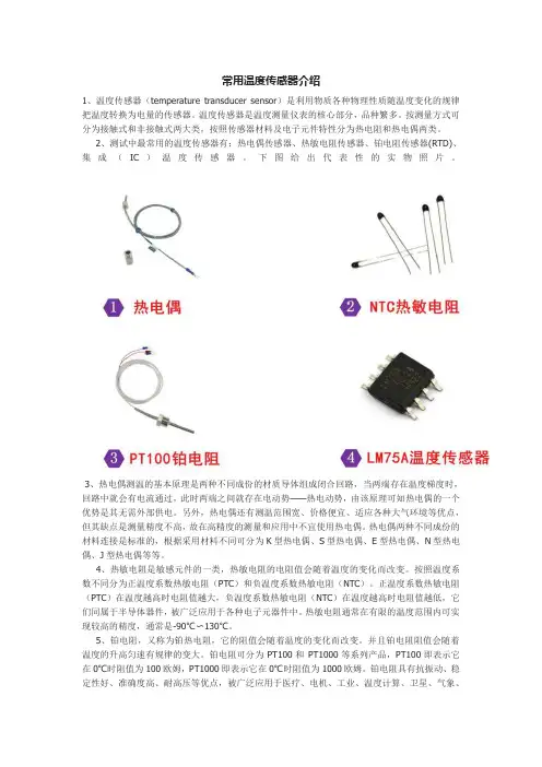
常用温度传感器介绍1、温度传感器(temperature transducer sensor)是利用物质各种物理性质随温度变化的规律把温度转换为电量的传感器。
温度传感器是温度测量仪表的核心部分,品种繁多。
按测量方式可分为接触式和非接触式两大类,按照传感器材料及电子元件特性分为热电阻和热电偶两类。
2、测试中最常用的温度传感器有:热电偶传感器、热敏电阻传感器、铂电阻传感器(RTD)、集成(IC)温度传感器。
下图给出代表性的实物照片。
3、热电偶测温的基本原理是两种不同成份的材质导体组成闭合回路,当两端存在温度梯度时,回路中就会有电流通过,此时两端之间就存在电动势——热电动势,由该原理可知热电偶的一个优势是其无需外部供电。
另外,热电偶还有测温范围宽、价格便宜、适应各种大气环境等优点,但其缺点是测量精度不高,故在高精度的测量和应用中不宜使用热电偶。
热电偶两种不同成份的材料连接是标准的,根据采用材料不同可分为K型热电偶、S型热电偶、E型热电偶、N型热电偶、J型热电偶等等。
4、热敏电阻是敏感元件的一类,热敏电阻的电阻值会随着温度的变化而改变。
按照温度系数不同分为正温度系数热敏电阻(PTC)和负温度系数热敏电阻(NTC)。
正温度系数热敏电阻(PTC)在温度越高时电阻值越大,负温度系数热敏电阻(NTC)在温度越高时电阻值越低,它们同属于半导体器件,被广泛应用于各种电子元器件中。
热敏电阻通常在有限的温度范围内可实现较高的精度,通常是-90℃〜130℃。
5、铂电阻,又称为铂热电阻,它的阻值会随着温度的变化而改变。
并且铂电阻阻值会随着温度的升高匀速有规律的变大。
铂电阻可分为PT100和PT1000等系列产品,PT100即表示它在0℃时阻值为100欧姆,PT1000即表示它在0℃时阻值为1000欧姆。
铂电阻具有抗振动、稳定性好、准确度高、耐高压等优点,被广泛应用于医疗、电机、工业、温度计算、卫星、气象、阻值计算等高精温度设备中。
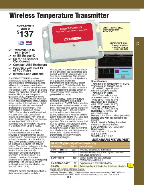
The OMWT-TEMP15 wirelesstemperature transmitter is a battery-operated digital temperature sensor with a microprocess or controlled 418 MHz FCC certified radio transmitter.The OMWT-TEMP15 has an on-board time of day clock that allows it to spend most of the time in a low-power quiescent state. At pre-determined time intervals, the clock will wake up the on-board microprocessor. Unique serial number information and digital temperature data are read from a digital temperature sensor. This information is combined with aCRC-16 error check and transmitted in a very short data packet that results in a transmitter “on” time of only 15 milliseconds. This architecture allows the OMWT-TEMP15 toconsume very little energy, resulting in a battery life of up to 3 years. The electronics are coated with a conformal rubber material thatprovides a moisture barrier against condensation. Submersion in water is not recommended. A hole in the top ABS cover permits a special tool to be inserted to activate the service switch. The device is shipped with the transmitter turned off (anytime the device is to be shipped, the transmitter should be turned off;otherwise, it must be placed in a shielded container to preventinterference that might cause shipping problems). The unit is started by pushing the service switch (the user feel the button click).When the service switch is pushed, a data transmission immediatelyOMWT-TEMP15Starts at$137ߜTransmits Up to180 m (600')*ߜ64-Bit Unique ID ߜUp to 100 SensorsCan CoexistߜCompact ABS Enclosure ߜComplies with Part 15of FCC RulesߜInternal Loop Antennanumerical dataOMWT-TEMP15, $137,shown larger than actual size.Wireless Temperature Transmitter。
外文翻译(原文)Distributed Temperature SensorIn the human living environment, temperature playing an extremely important role。
No matter where you live, engaged in any work, ever-present dealt with temperature under. Since the 18th century, industry since the industrial revolution to whether can master send exhibition has the absolute temperature touch. In metallurgy, steel, petrochemical, cement, glass, medicine industry and so on, can say almost eighty percent of industrial departments have to consider the factors with temperature. Temperature for industrial so important, thus promoting the development of the temperature sensor.Major general through three sensor development phase: analog integrated temperature sensor. The sensor is taken with silicon semiconductor integrated workmanship, therefore also called silicon sensor or monolithic integrated temperature sensor. Such sensing instruments have single function (only measuring temperature), temperature measurement error is smaller, price low, fast response, the transmission distance, small volume, micro-consumption electronic etc, suitable for long distance measurement temperature, temperature control, do not need to undertake nonlinear calibration, peripheral circuit is simple. It is currently the most common application at home and abroad, an integrated sensor。
简谈温度传感器及研究进展摘要:温度传感器是使用范围最广,数量最多的传感器,在日常生活,工业生产等领域都扮演着十分重要的角色。
从17世纪温度传感器首次应用以来,依次诞生了接触式温度传感器,非接触式温度传感器,集成温度传感器。
近年来在智能温度传感器在半导体技术,材料技术等新技术的支持下,温度传感器发展迅速。
由于智能温度传感器的软件和硬件的合理配合既可以大大增强传感器的功能、提高传感器的精度,又可以使温度传感器的结构更为简单和紧凑,使用更加方便,因此智能温度传感器是当今的一个研究热点。
微处理器的引入,使得温度信号的采集,记忆,存储,综合,处理与控制一体化,使温度传感器向智能化方向发展。
关键词:温度传感器;智能温度传感器;接触式温度传感器中图分类号:TP212.1 文献标识码:AAbstract:temperature transducer is used most widely, the largest number of sensors, in daily life, such as industrial production field plays a very important role.Since the 17th century temperature sensor for the first time application, was born in turn contact temperature sensor, non-contact temperature sensor, integrated temperature sensor.Intelligent temperature sensor in recent years in semiconductor technology, materials technology, under the support of new technologies such as the temperature sensor is developing rapidly.Due to the software and hardware of the intelligent temperature sensor reasonable matching can greatly enhance the function of the sensor, improve the precision of the sensor, and can make the temperature sensor has simple and compact structure, use more convenient, thus intelligent temperature sensor is a hot spot nowadays.The introduction of the microprocessor, which makes the temperature signal collection, memory, storage, comprehensive, processing and control integration, make the temperature sensor to the intelligent direction.Key words:temperature transducer; Smart temperature sensor; Contact temperature sensors前言:温度作为国际单位制的七个基本量之一,测量温度的传感器的各种各样,温度传感器是温度测量仪表的核心部分,十分重要。
分布式光纤温度传感器在电缆隧道中的应用文章探索了分布式光纤温度传感器(DTS)在电缆隧道中的应用,实验结果显示分布式光纤温度传感器能够在电缆隧道温度监测方面进行很好的应用。
系统温度范围:-40℃~85℃,测温光纤长:1.8km,测量温度精度:±1℃,空间分辨率:1.5m,为电缆隧道温度监测提供了科学依据。
标签:分布式光纤温度传感器;电缆;隧道;温度监测;拉曼散射Abstract:This paper explores the application of distributed fiber optic temperature sensor (DTS)in cable tunnel. The experimental results show that the distributed fiber optic temperature sensor can be used in cable tunnel temperature monitoring. The temperature range of the system is -40℃~85℃,the fiber length of measuring temperature is 1:1.8 km,the precision of measuring temperature is ±1℃,and the spatial resolution is 1:1.5 m,which provides a scientific basis for the temperature monitoring of cable tunnel.Keywords:distributed optical fiber temperature sensor;cable;tunnel;temperature monitoring;Raman scattering1 概述电网作为城市生命线工程系统的基础设施系统,由于涉及千家万户用电需求,是维持国民生产、生活的基础。
1. Using threaded adapters if necessary (included), screw the sensor into the desired location using Teflon tape to seal the threads. Use Flex-a-lite part no. 32082 (1 ½” diameter) or 32084 (1 ¾” diameter) to mount sensor inline with radiator hose (Preferred location - see Detail A). Alternatively, the sensor can be mounted in the intake manifold (see Detail B) or cylinder head or block (see Detail C). DO NOT overtighten.2. Carefully strip the ends of the wires. Fold the wire back on itself to effectively double the thickness (see Detail D ). Using a quality crimping tool, crimp the female connectors provided on the ends. Attach the wires to terminals 10 & 11 on the VSC (it doesn’t matter which wire goes to which spade, but both wires must be connected). Make sure the temperature. sensor wires are at least 2-3” away from exhaust manifolds or other extreme heat sources.3. Start the vehicle and check for leaks. When the engine has reached desired operating temperature, adjust the VSC to turn the fan(s) on (see page 2). Detail A Detail B Important:Before beginning, be sure that the Variable Speed Control unit (VSC) is mounted close enough to the temperature sensor so that the wires will reach the control unit. The lead on the sensor is approxi-mately 4 feet.Installation Instructions#31163 Variable Speed Control with Screw-in Temperature Sensor01-11-08 Page 1 of 2 part no. 91163FOLLOW THESE INSTRUCTIONS CAREFULLY TO A VOID DAMAGING THE CONTROL UNIT, FAN MOTORS, AND YOUR VEHICLE! WHEN CRIMPING WIRES, ALWAYS USE A QUALITYCRIMPING TOOL (DO NOT USE PLIERS). Detail CDetail DPage 2 of 2 01-11-08 part no. 91163The Flex-a-lite Limited WarrantyFlex-a-lite Consolidated, 7213-45th St. Ct. E. Fife, WA 98424, Telephone No. 253-922-2700, warrants to the original purchasing user, that all Flex-a-lite products to be free of defects in material and workmanship for a period of 365 days (1 year) from date of purchase. Flex-a-lite products failing within 365 days (1 year) from date of purchase may be returned to the factory through the point of purchase, transportation charges prepaid. If, on inspection, cause of failure is determined to be defective material or workmanship and not by misuse, accidental or improper installation, Flex-a-lite will replace the product free of charge, transportation prepaid. Flex-a-lite will not be liable for incidental, progressive or consequential damages. Some states do not allow the exclusion or limitation of incidental or consequential damages, so the above limitation or exclusion may not apply to you. This warranty gives you specific legal rights and you may have other rights, which vary from state to state. The Flex-a-lite warranty is in compliance with the Magnuson-Moss Warranty Act of 1975.1. Turn ignition on. After 6 seconds, LED #L4 should light up. If not, check to make sure that there is 12 Volts at terminal #9 on VSC. The delay is to allow starter to start the vehicle withoutthe fans drawing any power.2. With your engine running, engage the A/C. The fans should come on and cycle with the A/C clutch. LED’s #L1, L3 and L4 should be lit when fans are running. If they do not turn on, verifythat the A/C clutch is engaged and make sure you have a positive signal when the clutch is engaged at terminal #8 (OR negative signal at terminal on #7 if A/C compressor is triggered by a negative signal) on the VSC. Shut off A/C and let engine continue to idle, or drive the vehicle a short distance to bring the engine to operating temperature (monitor the vehicle’s tempera-ture gauge).3. Verify that the operating temperature has been reached by feeling the upper radiator hose. Hot water should be flowing through hose into the radiator. If the fans have not cycled on yet,slowly adjust the screw on the VSC until the fans cycle on. Turning the screw counterclock-wise will keep the engine at a lower temperature, and turning in the opposite direction will keep the engine at a higher temperature. NOTE: THE TOTAL MOVEMENT OF THE ADJUST-MENT SCREW IS ABOUT ¾ OF A TURN. TURNING THE SCREW BEYOND THE LIMITS WILL DAMAGE THE UNIT!4. Once desired temperature is set, let the engine continue to idle and make sure the fans willcycle to maintain desired temperature. When fans are running, LED’s #L1 and L4 should be lit. VERIFY THE DIRECTION OF BLADE ROTATION. IF THE FAN IS MOUNTED TO THE ENGINE SIDE OF THE RADIATOR, THE FAN SHOULD BE PULLING AIR THROUGH THE RADIATOR.Initial Start-up and Adjustment ProcedureThe Variable Speed Control has new features!At the set temperature, the fans will come on at 60%; this reduces the load on your charging system. If the temperature rises, the fan speed will increase. If your set temperature is 195°F, then between 195° and 205° the fan speed will increase from 60% to 100%. So after a 10-degree rise from the set point, the fans will be running at 100%.Turning screw counterclockwise = cooler temp.Turning screw clockwise = warmer temp.。
中英文资料外文翻译文献The introduction to The DS18B201. DESCRIPTIONThe DS18B20 digital thermometer provides 9-bit to 12-bit Celsius temperature measurements and has an alarm function with nonvolatile user programmable upper and lower trigger points. The DS18B20 communicates over a 1-Wire bus that by definition requires only one data line for communication with a central microprocessor. It has an operating temperature range of -55°C to +125°C and is accurate to ±0.5°C over the range of -10°C to +85°C. In addition, the DS18B20 can derive power directly from the data line (“parasite power”), eliminating the need for an external power supply.Each DS18B20 has a unique 64-bit serial code, which allows multiple DS18B20s to function on the same 1-Wire bus. Thus, it is simple to use one microprocessor to control many DS18B20s distributed over a large area. Applications that can benefit from this feature include HV AC environmental controls, temperature monitoring systems inside buildings, equipment, or machinery, and process monitoring and control systems.2.FEATURESUnique 1-Wire® Interface Requires Only One Port Pin for Communication1●Each Device has a Unique 64-Bit Serial Code Stored in an On-Board ROM●Multi-drop Capability Simplifies Distributed Temperature-Sensing Applications ●Requires No External Components●Can Be Powered from Data Line; Power Supply Range is 3.0V to 5.5V●Measures Temperatures from -55°C to +125°C (-67°F to +257°F)●±0.5°C Accuracy from -10°C to +85°C●Thermometer Resolution is User Selectable from 9 to 12 Bits●Converts Temperature to 12-Bit Digital Word in 750ms (Max)●User-Definable Nonvolatile (NV) Alarm Settings●Alarm Search Command Identifies and Addresses Devices Whose Temperature isOutside Programmed Limits●Software Compatible with the DS1822●Applications Include Thermostatic Controls, Industrial Systems, ConsumerProducts, Thermometers, or Any Thermally Sensitive System3.OVERVIEWFigure 1 shows a block diagram of the DS18B20, and pin descriptions are given in the Pin Description table. The 64-bit ROM stores the device’s unique serial code. The scratchpad memory contains the 2-byte temperature register that stores the digital output from the temperature sensor. In addition, the scratchpad provides access to the 1-byte upper and lower alarm trigger registers (TH and TL) and the 1-byte configuration register. The configuration register allows the user to set the resolution of the temperature to-digital conversion to 9, 10, 11, or 12 bits. The TH, TL, and configuration registers are nonvolatile (EEPROM), so they will retain data when the device is powered down.The DS18B20 uses Maxim’s exclusive 1-Wire bus protocol that implements bus communication using one control signal. The control line requires a weak pull up resistor since all devices are linked to the bus via a 3-state or open-drain port (the DQ2pin in the case of the DS18B20). In this bus system, the microprocessor (the master device) identifies and addresses devices on the bus using each device’s unique 64-bit code. Because each device has a unique code, the number of devices that can be addressed on one DS18B20 bus is virtually unlimited. The 1-Wire bus protocol, including detailed explanations of the commands and “time slots,” is covered in the 1-Wire Bus System section.Another feature of the DS18B20 is the ability to operate without an external power supply. Power is instead supplied through the 1-Wire pull up resistor via the DQ pin when the bus is high. The high bus signal also charges an internal capacitor (CPP), which then supplies power to the device when the bus is low. This method of deriving power from the 1-Wire bus is referred to as “parasite power.” As an alternative, the DS18B20 may also be powered by an external supply on VDD.Figure 1.DS18B20 Block Diagram4.OPERATION—MEASURING TEMPERATURThe core functionality of the DS18B20 is its direct-to-digital temperature sensor. The resolution of the temperature sensor is user-configurable to 9, 10, 11, or 12 bits, corresponding to increments of 0.5°C, 0.25°C, 0.125°C, and 0.0625°C, respectively. The default resolution at power-up is 12-bit. The DS18B20 powers up in a low-power idle state. To initiate a temperature measurement and A-to-D conversion, the master must issue a Convert T [44h] command. Following the conversion, the resulting3thermal data is stored in the 2-byte temperature register in the scratchpad memory and the DS18B20 returns to its idle state. If the DS18B20 is powered by an external supply, the master can issue “read time slots” (see the 1-Wire Bus System section) after the Convert T command and the DS18B20 will respond by transmitting 0 while the temperature conversion is in progress and 1 when the conversion is done. If the DS18B20 is powered with parasite power, this notification technique cannot be used since the bus must be pulled high by a strong pull up during the entire temperature conversion.The DS18B20 output temperature data is calibrated in degrees Celsius; for Fahrenheit applications, a lookup table or conversion routine must be used. The temperature data is stored as a 16-bit sign-extended two’s complement number in the temperature register (see Figure 2). The sign bits (S) indicate if the temperature is positive or negative: for positive numbers S = 0 and for negative numbers S = 1. If the DS18B20 is configured for 12-bit resolution, all bits in the temperature register will contain valid data. For 11-bit resolution, bit 0 is undefined. For 10-bit resolution, bits 1 and 0 are undefined, and for 9-bit resolution bits 2, 1, and 0 are undefined. Table 1 gives examples of digital output data and the corresponding temperature reading for 12-bit resolution conversions.4Table 1.Temperature/Data Relationship5.64-BIT LASERED ROM CODEEach DS18B20 contains a unique 64–bit code (see Figure 3) stored in ROM. The least significant 8 bits of the ROM code contain the DS18B20’s 1-Wire family code: 28h. The next 48 bits contain a unique serial number. The most significant 8 bits contain a cyclic redundancy check (CRC) byte that is calculated from the first 56 bits of the ROM code. The 64-bit ROM code and associated ROM function control logic allow the DS18B20 to operate as a 1-Wire device using the protocol detailed in the 1-Wire Bus System section.Figure 3.64-Bit Lasered ROM Code6.MEMORYThe DS18B20’s memory is organized as shown in Figure 4. The memory consists of an SRAM scratchpad with nonvolatile EEPROM storage for the high and low alarm trigger registers (TH and TL) and configuration register. Note that if the DS18B20 alarm function is not used, the TH and TL registers can serve as general-purpose memory.Byte 0 and byte 1 of the scratchpad contain the LSB and the MSB of the temperature register, respectively. These bytes are read-only. Bytes 2 and 3 provide access to TH and TL registers. Byte 4 contains the configuration register data. Bytes 5, 6, and 7 are reserved for internal use by the device and cannot be overwritten. Byte 8 of the scratchpad is read-only and contains the CRC code for bytes 0 through 7 of the scratchpad. The DS18B20 generates this CRC using the method described in the CRC Generation section.Data is written to bytes 2, 3, and 4 of the scratchpad using the Write Scratchpad [4Eh] command; the data must be transmitted to the DS18B20 starting with the least56significant bit of byte 2. To verify data integrity, the scratchpad can be read (using the Read Scratchpad [BEh] command) after the data is written. When reading the scratchpad, data is transferred over the 1-Wire bus starting with the least significant bit of byte 0. To transfer the TH, TL and configuration data from the scratchpad to EEPROM, the master must issue the Copy Scratchpad [48h] command.7.CONFIGURATION REGISTERByte 4 of the scratchpad memory contains the configuration register, which is organized as illustrated in Figure 5. The user can set the conversion resolution of the DS18B20 using the R0 and R1 bits in this register as shown in Table 2. The power-up default of these bits is R0 = 1 and R1 = 1 (12-bit resolution). Note that there is a direct tradeoff between resolution and conversion time. Bit 7 and bits 0 to 4 in the configuration register are reserved for internal useby the device and cannot be overwritten.8.1-WIRE BUS SYSTEMThe 1-Wire bus system uses a single bus master to control one or more slave devices. The DS18B20 is always a slave. When there is only one slave on the bus, the system is referred to as a “single-drop” system; the system is “multi-drop” if there are multiple slaves on the bus. All data and commands are transmitted least significant bit first over the 1-Wire bus. The following discussion of the 1-Wire bus system is broken down into three topics: hardware configuration, transaction sequence, and1-Wire signaling (signal types and timing).9.TRANSACTION SEQUENCEThe transaction sequence for accessing the DS18B20 is as follows:Step 1. InitializationStep 2. ROM Command (followed by any required data exchange)Step 3. DS18B20 Function Command (followed by any required data exchange)It is very important to follow this sequence every time the DS18B20 is accessed, as the DS18B20 will not respond if any steps in the sequence are missing or out of order. Exceptions to this rule are the Search ROM [F0h] and Alarm Search [ECh] commands. After issuing either of these ROM commands, the master must return to Step 1 in the sequence.(1)INITIALIZATIONAll transactions on the 1-Wire bus begin with an initialization sequence. The initialization sequence consists of a reset pulse transmitted by the bus master followed7by presence pulse(s) transmitted by the slave(s). The presence pulse lets the bus master know that slave devices (such as the DS18B20) are on the bus and are ready to operate.(2)ROM COMMANDSAfter the bus master has detected a presence pulse, it can issue a ROM command. These commands operate on the unique 64-bit ROM codes of each slave device and allow the master to single out a specific device if many are present on the 1-Wire bus. These commands also allow the master to determine how many and what types of devices are present on the bus or if any device has experienced an alarm condition. There are five ROM commands, and each command is 8 bits long. The master device must issue an appropriate ROM command before issuing a DS18B20 function command.1.SEARCH ROM [F0h]When a system is initially powered up, the master must identify the ROM codes of all slave devices on the bus, which allows the master to determine the number of slaves and their device types. The master learns the ROM codes through a process of elimination that requires the master to perform a Search ROM cycle (i.e., Search ROM command followed by data exchange) as many times as necessary to identify all of the slave devices. If there is only one slave on the bus, the simpler Read ROM command can be used in place of the Search ROM process.2.READ ROM [33h]This command can only be used when there is one slave on the bus. It allows the bus master to read the slave’s 64-bit ROM code without using the Search ROM procedure. If this command is used when there is more than one slave present on the bus, a data collision will occur when all the slaves attempt to respond at the same time.3.MATCH ROM [55h]The match ROM command followed by a 64-bit ROM code sequence allows8the bus master to address a specific slave device on a multi-drop or single-drop bus. Only the slave that exactly matches the 64-bit ROM code sequence will respond to the function command issued by the master; all other slaves on the bus will wait for a reset pulse.4.SKIP ROM [CCh]The master can use this command to address all devices on the bus simultaneously without sending out any ROM code information. For example, the master can make all DS18B20s on the bus perform simultaneous temperature conversions by issuing a Skip ROM command followed by a Convert T [44h] command. Note that the Read Scratchpad [BEh] command can follow the Skip ROM command only if there is a single slave device on the bus. In this case, time is saved by allowing the master to read from the slave without sending the device’s 64-bit ROM code. A Skip ROM command followed by a Read Scratchpad command will cause a data collision on the bus if there is more than one slave since multiple devices will attempt to transmit data simultaneously.5.ALARM SEARCH [ECh]The operation of this command is identical to the operation of the Search ROM command except that only slaves with a set alarm flag will respond. This command allows the master device to determine if any DS18B20s experienced an alarm condition during the most recent temperature conversion. After every Alarm Search cycle (i.e., Alarm Search command followed by data exchange), the bus master must return to Step 1 (Initialization) in the transaction sequence.(3)DS18B20 FUNCTION COMMANDSAfter the bus master has used a ROM command to address the DS18B20 with which it wishes to communicate, the master can issue one of the DS18B20 function commands. These commands allow the master to write to and read from the D S18B20’s scratchpad memory, initiate temperature conversions and determine the power supply mode.91.CONVERT T [44h]This command initiates a single temperature conversion. Following the conversion, the resulting thermal data is stored in the 2-byte temperature register in the scratchpad memory and the DS18B20 returns to its low-power idle state. If the device is being used in parasite power mode, within 10µs (max) after this command is issued the master must enable a strong pull up on the 1-Wire bus. If the DS18B20 is powered by an external supply, the master can issue read time slots after the Convert T command and the DS18B20 will respond by transmitting a 0 while the temperature conversion is in progress and a 1 when the conversion is done. In parasite power mode this notification technique cannot be used since the bus is pulled high by the strong pull up during the conversion.2.READ SCRATCHPAD [BEh]This command allows the master to read the contents of the scratchpad. The data transfer starts with the least significant bit of byte 0 and continues through the scratchpad until the 9th byte (byte 8 – CRC) is read. The master may issue a reset to terminate reading at any time if only part of the scratchpad data is needed.3.WRITE SCRATCHPAD [4Eh]This comm and allows the master to write 3 bytes of data to the DS18B20’s scratchpad. The first data byte is written into the TH register (byte 2 of the scratchpad), the second byte is written into the TL register (byte 3), and the third byte is written into the configuration register (byte 4). Data must be transmitted least significant bit first. All three bytes MUST be written before the master issues a reset, or the data may be corrupted.4.COPY SCRATCHPAD [48h]This command copies the contents of the scratchpad TH, TL and configuration registers (bytes 2, 3 and 4) to EEPROM. If the device is being used in parasite power mode, within 10µs (max) after this command is issued the master must enable a10strong pull-up on the 1-Wire bus.5.RECALL E2 [B8h]This command recalls the alarm trigger values (TH and TL) and configuration data from EEPROM and places the data in bytes 2, 3, and 4, respectively, in the scratchpad memory. The master device can issue read time slots following the Recall E2command and the DS18B20 will indicate the status of the recall by transmitting 0 while the recall is in progress and 1 when the recall is done. The recall operation happens automatically at power-up, so valid data is available in the scratchpad as soon as power is applied to the device.6.READ POWER SUPPL Y [B4h]The master device issues this command followed by a read time slot to determine if any DS18B20s on the bus are using parasite power. During the read time slot, parasite powered DS18B20s will pull the bus low, and externally powered DS18B20s will let the bus remain high.10.WIRE SIGNALINGThe DS18B20 uses a strict 1-Wire communication protocol to ensure data integrity. Several signal types are defined by this protocol: reset pulse, presence pulse, write 0, write 1, read 0, and read 1. The bus master initiates all these signals, with the exception of the presence pulse.(1)INITIALIZATION PROCEDURE—RESET AND PRESENCE PULSES All communication with the DS18B20 begins with an initialization sequence that consists of a reset pulse from the master followed by a presence pulse from the DS18B20. This is illustrated in Figure 6. When the DS18B20 sends the presence pulse in response to the reset, it is indicating to the master that it is on the bus and ready to operate.During the initialization sequence the bus master transmits (TX) the reset pulse by pulling the 1-Wire bus low for a minimum of 480µs. The bus master then releases11the bus and goes into receive mode (RX). When the bus is released, the 5kΩ pull-up resistor pulls the 1-Wire bus high. When the DS18B20 detects this rising edge, it waits 15µs to 60µs and then transmits a presence pulse by pulling the 1-Wire bus low for 60µs to 240µs.TimingBus master pulling lowDS18B20 pulling lowResistor pullupFigure 6.Initialization Timing(2)READ/WRITE TIME SLOTSThe bus master writes data to the DS18B20 during write time slots and reads data from the DS18B20 during read time slots. One bit of data is transmitted over the 1-Wire bus per time slot.1.WRITE TIME SLOTSThere are two types of write time slots: “Write 1” time slots and “Write 0” time slots. The bus master uses a Write 1 time slot to write a logic 1 to the DS18B20 and a Write 0 time slot to write a logic 0 to the DS18B20. All write time slots must be a minimum of 60µs in duration with a minimum of a 1µs recovery time between individual write slots. Both types of write time slots are initiated by the master pulling the 1-Wire bus low (see Figure 7).To generate a Write 1 time slot, after pulling the 1-Wire bus low, the bus master must release the 1-Wirebus within 15µs. When the bus is released, the 5kΩ pull-up resistor will pull the bus high. To generate a Write 0 time slot, after pulling the 1-Wire1213bus low, the bus master must continue to hold the bus low for the duration of the time slot (at least 60µs).The DS18B20 samples the 1-Wire bus during a window that lasts from 15µs to 60µs after the master initiates the write time slot. If the bus is high during the sampling window, a 1 is written to the DS18B20. If the line is low, a 0 is written to the DS18B20.DS18B20Write Time SlotSTART OF SLOTVccBus master pulling low Resistor pullupFigure 7.DS18B20 Write Time Slot2.READ TIME SLOTSThe DS18B20 can only transmit data to the master when the master issues read time slots. Therefore, the master must generate read time slots immediately after issuing a Read Scratchpad [BEh] or Read Power Supply [B4h] command, so that the DS18B20 can provide the requested data. In addition, the master can generate read time slots after issuing Convert T [44h] or Recall E 2 [B8h] commands to find out the status of the operation.All read time slots must be a minimum of 60µs in duration with a minimum of a 1µs recovery time between slots. A read time slot is initiated by the master device pulling the 1-Wire bus low for a minimum of 1µs and then releasing the bus (see Figure 8). After the master initiates the read time slot, the DS18B20 will begin transmitting a 1 or 0 on bus. The DS18B20 transmits a 1 by leaving the bus high andtransmits a 0 by pulling the bus low. When transmitting a 0, the DS18B20 will release the bus by the end of the time slot, and the bus will be pulled back to its high idle state by the pull up resister. Output data from the DS18B20 is valid for 15µs after the falling edge that initiated the read time slot. Therefore, the master must release the bus and then sample the bus state within 15µs from the start of the slot.VccBus master pulling lowResistor pullupDS18B20 pulling lowFigure 8.DS18B20 Read Time Slot1415DS18B20介绍1.说明DS18B20数字式温度传感器提供9位到12位的摄氏温度测量,并且有用户可编程的、非易失性温度上下限告警出发点。
Page 1/17Data Sheet 202755JUMO CTI-500Inductive Conductivity/Concentration and Temperature Transmitter with switch contacts Type 202755Brief descriptionThe instrument is used for the measurement/control of conductivity or concentration in liquid media. It is particularly suitable for application in media where severe deposits of dirt, oil, grease or gypsum/lime precipitates are to be expected. The integrated temperature measurement enables fast and accurate temperature compensation, which is of special importance when measuring conductivity. Additional functions permit the combined changeover of measuring range and temperature coefficient.Two built-in switching outputs can be freely programmed to monitor conductivity/concentration and /or temperature limits. It is also possible to assign alarm and control functions (dilution).The instrument is operated either from the membrane keypad and plain-text graphics display (operator language can be changed over) or through the user-friendly PC setup program. The display can be read off by simply rotating the housing cover. This applies to the installation both in horizontally and vertically arranged pipes. By using the setup program, the instrument configuration data can be saved for plant documentation and printed out. To prevent any tampering, the instrument can also be supplied without keypad or display. In this case, the setup program is needed for programming.The JUMO CTI-500 is available either as a combined unit (transmitter and measuring cell together in one unit) or as a split version (transmitter and cell connected by cable). The split version is particularly suitable for plant subjected to strong vibration and/or significant heat radiation at the measurement point, or for installation on sites that are difficult to access.Immersion models up to 2000 mm are available for application in open containers or sluices. Typical areas of application: Freshwater and wastewater engineering, air conditioning systems and cooling tower monitoring (dilution control), rinsing baths (e.g. monitoring electroplating baths), inlet and final checks in factory water treatment plant, concentration monitoring, vehicle wash plant, etc.Block structureKey features•Activation of up to four ranges •Activation of up to four temperature coefficients •Concentration measurement of - caustic soda NaOH - nitric acid HNO 3- a freely definable curve(through the setup program)•Fast-response temperature sensor •Temperature compensation - linear- natural water- individual characteristic (learning function)•Operation- via keypad and LC display - through setup program•Operator languages: English, French, German, Italian, Dutch, Spanish, Polish, Portuguese, Russian, Swedish •By using the setup program:- user-friendly programming - plant documentation•Learning function for the temperature coefficient•Individual characteristic for concentration indication •Dilution controlPage 2/17 Data Sheet 202755Functional description The inductive measurement method permits largely maintenance-free acquisition of the specific conductivity, even in the toughest media conditions. As opposed to the conductive measurement method, problems such as electrode decomposition and polarization do not occur.The conductivity is measured using an inductive probe. A sinusoidal a.c. voltage feeds the transmitting coil. Depending on the conductivity of the liquid to be measured, a current is induced in the receiver coil. The current is proportional to the conductivity of the medium.Instrument descriptionMeasuring cellThe measuring cell consists of a hermetically sealed polypropylene (PP) or polyvinyl-idenefluoride (PVDF) body inside which the two measurement coils are arranged. A bore in the measuring cell enables the medium to flow through. The measurement principle entails an inevitable electrical isolation(1)Temperature sensor, exposed(1a)optionally: internal(2)Cell body in PP(3)Measurement coils(4)Liquid loopExposed temperature sensorThe sensor (in a stainless steel sleeve) exhibits a very fast response to temperature variations. This is especially important for CIP processes (phase separation).Internal temperature sensorThe sensor is integrated in the PP body. This construction ensures that no metal parts come into contact with the sample medium (important with corrosive media). However, temperature acquisition is somewhat slower here.Temperature compensationSince conductivity largely depends on thetemperature of the medium, it is usuallynecessary to compensate for the temperatureeffect.The instrument allows both linear and non-linear temperature compensation.If required, temperature compensation can beswitched off, for example, when thetemperature conditions on the measurementsite are stable or when temperaturecompensation is carried out in the software, inexternal evaluation devices (PLC or similar).Process connectionsTo cover a wide variety of applications, theinstrument can be supplied with differentprocess connections (also as an immersionmodel), see dimensions.Installation at the measurementpointThe operating position is generallyunrestricted. However, it is essential to ensurethat there is a continuous exchange of thesample liquid in the flow channel.TransmitterThe CTI-500 transmitter has been designedfor use on site. A rugged housing protects theelectronics and the electrical connectionsfrom corrosive environmental conditions(IP67).A vent screw with a PTFE membrane preventscondensation.OperationThe JUMO CTI-500 can be operated eitherfrom the instrument keys and the graphics LCdisplay and/or through the setup programfrom a PC or laptop.The instrument can be secured againstunauthorized alteration by a password.Functions of the outputsAnalog outputs•One analog signal output for conductivity/concentration and temperaturerespectively.•The analog output signals are freelyscalable (range start and end values).•The response of the analog outputs toover/underrange or alarm can beprogrammed.•Simulation of the signal output:The analog signal outputs can be freely setin the manual mode.Application: “Dry-run” start-up of the plant,trouble-shooting, servicing.Displays and controls(1)Graphics LC display(2)LEDs for the switching status indication of the outputs K1 and K2(3)KeysVersion without a displayOperation/configuration throughthe setup program onlyVersion with a displayOperation/configuration fromthe keys or through the setupprogramPage 3/17Data Sheet 202755Graphics LC display (1)Switching output 1 or 2 is active (2)Binary input 1 or 2 is operated (3)Keypad is inhibited (4)Alarm has been activated (5)Instrument is in manual mode (6)Instrument status (7)Temperature of medium (8)Conductivity measurement (9)Unit of conductivity measurementSwitching outputsThe instrument features two floating switching outputs (solid-state relays) as standard.These can be used freely for monitoring the conductivity/concentration or the temperature.The following functions can be assigned:❏Limit monitoring (MAX. or MIN. limit comparator) with programmable hysteresis ❏Pulse function (the output switches briefly on reaching the switching point, then opens again).❏Pull-in and drop-out delay ❏Inverted switching outputs❏Response to overrange/underrange or with activated measuring circuit monitoring (pull-in/drop-out).❏“Calibration timer run down" signal.Contact functions(1)(2)(3)(4)(5)(6)(7)(8)(9)Alarm window 1Alarm window 2Pulse contactTrigger conditions longer than pulse timePulse contactTrigger conditions shorter than pulse timeBinary inputsThe two binary inputs serve to implement the following functions:–Key inhibit –HOLD mode–4-fold range changeover–4-fold temperature coefficient changeover–Initiation of dilution function and biocide dosingSpecial functions•The learning function for the temperature coefficient enables exact measurement of media with a non-linear characteristic. During a temperature change, the instrument “learns” the temperature coefficient of the present medium and stores the profile. The stored values then enable the correct indication of thetemperature-compensated conductivity.•Individual characteristic for concentration indication.An individual characteristic with 20 interpolation points can be enteredthrough the setup program. This function can be used to generate specialcharacteristics for specific media (e.g. special detergents). This results in correct measurements that contribute to assuring the quality and saving costs.•Dilution controlVarious processes that find theirapplication in wet cooling towers arestored as sequence control (biocide dosing and subsequent inhibiting of dilution). Additional information can be found in the operating manual.•Calibration timerThe calibration timer draws your attention to a calibration schedule. This function is activated by entering a number of days, after which recalibration has to be carried out (plant or operator requirement).Page 4/17Data Sheet 202755Technical dataGeneralA/D converterresolution:15 bitsampling time:500msec=2 meas. per secSupplyFor operation with SELV andPELV circuits.As standard:19 — 31V DC (24V DC nominal),the instrument incorporates reverse-polarity protectionripple:< 5%extra code 844:24 V AC ±10%, 50 — 60 Hzpower consumptionwith display:≤ 3 Wpower consumptionwithout display:≤ 2.6 WRating of the solid-state relaysU < 50 V AC/DCI ≤ 200 mAElectrical connectionplug-in screw terminals 2.5 mm2 orM12 plug/socket connectorsDisplay (option)graphics LCD with background lighting; contrast is adjustabledimensions: 62 x 23 mmPermissible ambient temp. (transmitter)-5 to +50°Cmax. 93% rel. humidity, no condensationPermissible storage temp. (transmitter)-10 to +75°Cmax. 93% rel. humidity, no condensationEnclosure protection (transmitter)IP67Housingpolyamide (PA)Weightdepending on version and processconnectionapprox. 0.3 — 2kgConductivity/concentrationtransmitterConcentration measurement(implemented in the instrument software)–NaOH (caustic soda)0 —15 % by weight or 25 — 50 % byweight–HNO3 (nitric acid)0 —25 % by weight or 36 — 82 % byweight–customer-specific concentration curve,reely programmable through the setupprogram (see “special functions”)Calibration timeradjustable: 0 — 999 days (0 = off)Output signal for conductivity/concentration0 — 10 V / 10 — 0 V2 — 10 V / 10 — 2 V0 — 20 mA / 20 — 0 mA4 — 20 mA / 20 — 0.4 mAThe output signal is freely scalable.Burden≤ 500Ω for current output≥ 2kΩ for voltage outputAnalog output with “Alarm”Low (0 mA / 0 V / 3.4 mA / 1.4 V)orHigh (22.0 mA / 10.7 V)ora fixed settingMeasuring rangesFour ranges can be selected. One of theseranges can be activated via an external switchor a PLC.Note:The overall tolerance is made up of thetolerance of the transmitter + the tolerance ofthe sensor.Temperature transmitterTemperature acquisitionmanually -200 to 25.0 to 150°C/°For automaticallyTemperature measuring range-200 to 150°C/°FCharacteristiclinearAccuracy≤ 0.5% of measuring rangeAmbient temperature error≤ 0.1%/°CResponse timewith exposed temperature sensort09≤ 6 secwith internal temperature sensort09≤ 2 minOutput signal for temperature0 — 10 V / 10 — 0 V2 — 10 V / 10 — 2 V0 — 20 mA / 20 — 0 mA4 — 20 mA / 20 — 0.4 mAThe output signal is freely scalable withinthe range -20 to +200°C.The sensor can be applied within the range-10 to +100°C.Burden≤ 500Ω for current output≥ 2kΩ for voltage outputMeas. rangesTransmitterTolerance(in % of rangespan)0—500 µS/cm≤0.5%0—1000 µS/cm0—2000 µS/cm0—5000 µS/cm0—10 mS/cm0—20 mS/cm0—50 mS/cm0—100 mS/cm0—200 mS/cm0—500 mS/cm0—1000 mS/cm0—2000 mS/cm aa not compensated for temperatureFunction of the binary inputsSetting parameters Binary input 1Binary input 2Measuring range/ temperature coefficient changeover Range1/TC1open open Range2/TC2closed open Range3/TC3open closed Range4/TC4closed closedKey inhibit closed X “Hold” function X closed Start dilution function close (edge 0 - 1)openStop dilution function open close (edge 0 - 1)Page 5/17 Data Sheet 202755Analog output for “Alarm”Low (0 mA / 0 V / 3.4 mA / 1.4 V)orHigh (22.0 mA / 10.7 V)ora fixed settingTemperature compensationReference temperature15 to 30°C, adjustableTemperature coefficient0.0 to 5.5%/°C, adjustableCompensation range-20 to 150°CFunction–linear–natural water (EN 27 888)–non-linear (learning function, see specialfunctions)SensorMaterialPP (polypropylene), suitable for foodstuffsNote:Temperature, pressure and samplemedium affect the life of the cell!Temperature of the sample mediumPressure10bar max. at 20°C6 bar max. at 60°CProcess-connectionmax.temperature16870660°C16960761769080°Cshort term100°CMeasuring rangeSensorTolerance(in % of rangespan)0—500 µS/cm≤1%0—1000 µS/cm0—2000 µS/cm≤0.5%0—5000 µS/cm0—10 mS/cm0—20 mS/cm0—50 mS/cm0—100 mS/cm0—200 mS/cm0—500 mS/cm0—1000 mS/cm≤1%0—2000 mS/cm a1a not compensated for temperature. Electrical connection - head transmitter (transmitter with cable glands (-82))Data Sheet 202755Page 6/17Data Sheet 202755Page 7/17 Electrical connection (transmitter with M12 connectors (-83))Data Sheet 202755Page 8/17 DimensionsSensor (detail)Page 9/17Data Sheet 202755DimensionsDrilling diagramTransmitter with M12 plug connectors and M12 socket connectorsVersion:Transmitter with separate sensor (split version)(basic type extensions /20, /25, /60 or /65)Transmitter with M16 cable gland(only for the "head transmitter" model)Data Sheet 202755Page 10/17Dimensions / Process connections (head transmitter)Data Sheet 202755Page 11/17Dimensions / Process connections (separate sensor)Page 12/17Data Sheet 202755Dimensions (separate sensor as immersion model)Optional accessory:flange DN32, part no. 00083375Optional accessory:flange DN50, part no. 00083376Page 13/17Data Sheet 202755Mounting examplesWeld-on threaded pipe adapterDN50, DIN 11 851(mating component for proc. connection 607),part no. 00085020DN ø D L H MaterialMaximum temperature Part no.324098172PVC+60°C00439247405011817700439249324088179PP +80°C00449511405010218100449514506312418100449516Data Sheet 202755Page 14/17 Kit for pipe mountingPage 15/17Data Sheet 202755Order details: CTI-500 as “Head transmitter”x = standardo = available as an option(1)Basic type202755JUMO CTI-500 - Inductive transmitter/switching device for conductivity/concentration and temperature (2)Basic type extensions10head transmitter without display/keypad a a The PC setup program is required for programming the instrument, see accessories 15head transmitter with display/keypad (3)Process connection o o 168PVC union nut G11/2A b,cb Special tee is not included in delivery, see accessoriesc Maximum temperature of medium: 60 °Co o 169stainless steel union nut G11/2A bo o 607screwed pipe fitting DN50, DIN 11 851(MK DN50, milk cone)o o 617clamp connection 21/2", ISO 2852d d Mounting items (mounting brackets) do not come with delivery. If required, please include in your order (accessories)o o 690SMS 2"(4)Immersion length o o 0see dimensions (5)Electrical connection o o 82cable glandso o 83M12 plug/socket connectors (instead of the cable glands)e e If required, order 1 set M12 plug / socket connectors, see accessorieso o 84two M16 cable glands and one blind grommet (6)Extra codes x x 000no extra codeo o 268internal temperature sensor o o 768cell material PVDF f fOnly with process connections 168 and 169, in combination with extra code 268o o844supply 24AC V ±10%(1)(2)(3)(4)(5)(6)(6)Order code /---/,...aaList extra codes in sequence, separated by commasOrder example202755/10-108--82/000Page 16/17Data Sheet 202755Order details: CTI-500 as “Transmitter with separate sensor”x = standard0 = available as an option – = not available(1)Basic type202755JUMO CTI-500 - Inductive transmitter/switching device for conductivity/concentration and temperature (2)Basic type extensions20transmitter without display/keypad (without sensor)a,b a The PC setup program is required for programming the instrument, see accessoriesb A calibration kit is absolutely essential for commissioning. If required, please include in your order (accessories)25transmitter with display/keypad (without sensor)b60transmitter without display/keypad including sensor (cable length: 10 m)a 65transmitter with display/keypad including sensor (cable length: 10 m)80replacement sensor with a 10 m long cable without transmitter b,c c Mounting items (union/ring nuts, mounting brackets) do not come with delivery. If required, please include in your order (accessories)(3)Process connection x x000not availableo o o 168PVC union nut G11/2A (media temperature: 60°C max.)d,e d Special tee is not included in delivery e Maximum temperature of medium: 60 °Co o o 169stainless steel union nut G11/2A do o o 607screwed pipe fitting DN50, DIN 11 851(MK DN50, milk cone)o o o 617clamp connection 21/2", ISO 2852c o o o 690SMS 2"o o o 706immersion model(4)Immersion length x x0not available o o o 5000500 mm o o o 10001000 mm o o o 15001500 mmo o o 20002000 mm (max. length)o o oxxxxspecial length (in 250 mm steps; e.g. 0250; 0750; 1250; 1750)(5)Electrical connectionx21attached cable with M12 socket connector on separate sensor o o o o 82cable glands on the operating unito o o o 83M12 plug/socket connectors on operating unit f f If required, order 1 set M12 plug / socket connectors, see accessorieso o o o 84two cable glands and one blind grommet (6)Extra codes x x x x x 000no extra code--o o o268internal temperature sensor o o 768cell material PVDF g gOnly with process connections 168 and 169, in combination with extra code 268o o o o844supply voltage 24 V AC(1)(2)(3)(4)(5)(6)(6)Order code /---/,...aaList extra codes in sequence, separated by commasOrder example202755/65-108-1000-21/000Page 17/17Data Sheet 202755Stock items (shipment: 3 days after receipt of order)Production items(shipment: 10 days after receipt of order)AccessoriesTypePart no.202755/10-168-0-82/00000445842202755/15-168-0-82/00000445843202755/15-607-0-82/00000445845TypePart no.202755/65-607-0-82/00000445840TypePart no.Weld-on threaded adapter DN50, DIN 11 851 (mating component for process connection -607)00085020Special tee DN32, PVC, including threaded socket aa with anti-rotation lug - the cell can only be installed in the correct orientationmax. 60°C, mating component for process connection -16800439247Special tee DN40, PVC, including threaded socket a00439249Union nut G1 1/2, PVC00439199Union nut G1 1/2, stainless steel 00452039Ring nut DN50, DIN 11 85100343368Ring nut SMS DN2" 00345162Flange DN32, material: PPbbonly in conjunction with a separate sensor in the immersion version 202755/60-706-... or 202755/65-706-... or 202755/80-706-...00083375Flange DN50, material: PP b00083376Kit for pipe mounting, stainless steel 00515128Kit for DIN rail mounting00459903Shackle for CTI-500 sensor and immersion fitting with diameter 40 mm 00453191M12 socket connector, 5-pole, straight, for assembly by user necessary for versions 202755/xx-xxx-xxxx-83/xxx 00444313M12 plug connector, 8-pole, straight, for assembly by user 00444307M12 socket connector, 8-pole, straight, for assembly by user replacement part for sensor 202755/80...00444312PC setup software for JUMO CTI-50000447634PC interface cable with TTL / RS232 converter and adapter (serial connection cable)00350260PC interface cable with USB / TTL converter and two adapters (USB connection cable)00456352Switched-mode power supply for DIN rail mounting,Type PS5R-A24input voltage:AC 100to 240V /50to 60Hz output voltage:DC 24V , 0.3A00374661Cover with LC display and keypad (facilitates the programming of transmitters without display and keypad)00443725Special tee DN32, PPaincluding threaded socket (max. 80°C), mating component for process connection -16900449511Special tee DN40, PP a 00449514Special tee DN50, PP a00449516Calibration kit (for calibrating a replacement transmitter or replacement sensor)00459436M12 plug/socket connectors set, suitable for electrical connection 8300529482Additional concentration curves for the usual acids and lyes (20 interpolation points in tabular form),for entry on the CTI-500 through the setup program.on request。
毕业设计(论文)
外文文献翻译
文献、资料中文题目:多路温度传感器
文献、资料英文题目:Distributed Temperature Sensor 文献、资料来源:
文献、资料发表(出版)日期:
院(部):
专业:
班级:
姓名:
学号:
指导教师:
翻译日期: 2017.02.14
毕业论文(设计)外文翻译
题目:基于单片机的多路温度采集系统设计
系部名称:专业班级:
学生姓名:学号:
指导教师:教师职称:
多路温度传感器
一温度传感器简介
1.1温度传感器的背景
在人类的生活环境中,温度扮演着极其重要的角色。
无论你生活在哪里,从事什么工作,无时无刻不在与温度打着交道。
自 18 世纪工业革命以来,工业发展对是否能掌握温度有着绝对的联系。
在冶金、钢铁、石化、水泥、玻璃、医药等等行业,可以说几乎%80 的工业部门都不得不考虑着温度的因素。
温度对于工业如此重要,由此推进了温度传感器的发展。
1.2温度传感器的发展
传感器主要大体经过了三个发展阶段:模拟集成温度传感器。
该传感器是采用硅半导体集成工艺制成,因此亦称硅传感器或单片集成温度传感器。
此种传感器具有功能单一(仅测量温度)、测温误差小、价格低、响应速度快、传输距离远、体积小、微功耗等,适合远距离测温、控温,不需要进行非线性校准,外围电路简单。
它是目前在国内外应用最为普遍的一种集成传感器,典型产品有AD590、AD592、TMP17、LM135 等;模拟集成温度控制器。
模拟集成温度控制器主要包括温控开关、可编程温度控制器,典型产品有LM56、AD22105 和 MAX6509。
某些增强型集成温度控制器(例如 TC652/653)中还包含了A/D 转换器以及固化好的程序,这与智能温度传感器有某些相似之处。
但它自成系统,工作时并不受微处理器的控制,这是二者的主要区别;智能温度传感器。
能温度传感器(亦称数字温度传感器)是在20世纪90年代中期问世的。
它是微电子技术、计算机技术和自动测试技术(ATE)的结晶。
智能温度传感器内部都包含温度传感器、A/D 转换器、信号处理器、存储器(或寄存器)和接口电路。
有的产品还带多路选择器、中央控制器(CPU)、随机存取存储器(RAM)和只读存储器(ROM)。
智能温度传感器的特点是能输出温度数据及相关的温度控制量,适配各种微控制器(MCU);并且它是在硬件的基础上通过软件来实现测试功能的,其智能化程度也取决于软件的开发水平。
温度传感器的发展趋势。
进入21世纪后,温度传感器正朝着高精度、多功能、总线标准化、高可靠性及安全性、开发虚拟传感器和网络传感器、研制单片测温系统等高科技的方向迅速发展。
1.3单点与多点温度传感器
目前市场主要存在单点和多点两种温度测量仪表。
对于单点温测仪表,主要采用传统的模拟集成温度传感器,其中又以热电阻、热电偶等传感器的测量精度高,测量范围
大,而得到了普遍的应用。
此种产品测温范围大都在-200℃~800℃之间,分辨率12位,最小分辨温度在0.001~0.01 之间。
自带LED 显示模块,显示4位到16位不等。
有的仪表还具有存储功能,可存储几百到几千组数据。
该类仪表可很好的满足单个用户单点测量的需要。
多点温度测量仪表,相对与单点的测量精度有一定的差距,虽然实现了多路温度的测控,但价格昂贵。
针对目前市场的现状,本课题提出了一种可满足要求、可扩展的并且性价比高的单片机多路测温系统。
通过温度传感器 DS18B20采集,然后通过C51 单片机处理并在数码管上显示,可以采集室内或花房中四处不同位置的温度,用四个数码管来显示。
第一个数码管显示所采集的是哪一路,哪个通道;后三个数码管显示所采集通道的温度值,精确到0.1度。
二 系统的实现及相关技术
2.1.系统的实现
系统的实现采用多线连接,就是四个DS1820分别连接到单片机的四个IO 口,这种方案虽然占用单片机的四个IO 口,但在单片机IO 口不紧缺的情况下采用这种方案大大的简化了编程难度,缩短了设计周期,同时也能保证系统的稳定。
方案二的框图如“图1-1”所示
图1-1 DS1820多线连接方案
2.2.AT89C51单片机简介
AT89C51是一种带4K 字节FLASH 存储器(FPEROM —Flash Programmable and Erasable Read Only Memory )的低电压、高性能CMOS 8位微处理器,俗称单片机。
AT89C2051是一种带2K 字节闪存可编程可擦除只读存储器的单片机。
单片机的可擦除只读存储器可以反复擦除1000次。
该器件采用ATMEL 高密度非易失存储器制造技术制造,与工业标准的DS1820 DS1820 DS1820 DS1820 AT89C51
单片机
P1.0
P1.1
P1.2
P1.3
P3.4
显示单元 按键控制单元
MCS-51指令集和输出管脚相兼容。
由于将多功能8位CPU和闪烁存储器组合在单个芯片中,ATMEL的AT89C51是一种高效微控制器,AT89C2051是它的一种精简版本。
AT89C51单片机为很多嵌入式控制系统提供了一种灵活性高且价廉的方案。
外形及引脚排列如图“图1-2”所示
图1-2 AT89C51引脚图
主要特性:
²与MCS-51 兼容
²4K字节可编程FLASH存储器
²寿命:1000写/擦循环
²数据保留时间:10年
²全静态工作:0Hz-24MHz
²三级程序存储器锁定
²128³8位内部RAM
²32可编程I/O线
²两个16位定时器/计数器
²5个中断源
²可编程串行通道
²低功耗的闲置和掉电模式
²片内振荡器和时钟电路
管脚说明:
VCC:供电电压。
GND:接地。
P0口:P0口为一个8位漏级开路双向I/O口,每脚可吸收8TTL门电流。
当P0口的管脚第一次写1时,被定义为高阻输入。
P0能够用于外部程序数据存储器,它可以被定义为数据/地址的第八位。
在FIASH编程时,P0 口作为原码输入口,当FIASH进行校验时,P0输出原码,此时P0外部必须被拉高。
P1口:P1口是一个内部提供上拉电阻的8位双向I/O口,P1口缓冲器能接收输出4TTL门电流。
P1口管脚写入1后,被内部上拉为高,可用作输入,P1口被外部下拉为低电平时,将输出电流,这是由于内部上拉的缘故。
在FLASH编程和校验时,P1口作为第八位地址接收。
P2口:P2口为一个内部上拉电阻的8位双向I/O口,P2口缓冲器可接收,输出4个TTL门电流,当P2口被写“1”时,其管脚被内部上拉电阻拉高,且作为输入。
并因此作为输入时,P2口的管脚被外部拉低,将输出电流。
这是由于内部上拉的缘故。
P2口当用于外部程序存储器或16位地址外部数据存储器进行存取时,P2口输出地址的高八位。
在给出地址“1”时,它利用内部上拉优势,当对外部八位地址数据存储器进行读写时,P2口输出其特殊功能寄存器的内容。
P2口在FLASH编程和校验时接收高八位地址信号和控制信号。
P3口:P3口管脚是8个带内部上拉电阻的双向I/O口,可接收输出4个TTL门电流。
当P3口写入“1”后,它们被内部上拉为高电平,并用作输入。
作为输入,由于外部下拉为低电平,P3口将输出电流(ILL)这是由于上拉的缘故。
RST:复位输入。
当振荡器复位器件时,要保持RST脚两个机器周期的高电平时间。
ALE/PROG:当访问外部存储器时,地址锁存允许的输出电平用于锁存地址的地位字节。
在FLASH编程期间,此引脚用于输入编程脉冲。
在平时,ALE端以不变的频率周期输出正脉冲信号,此频率为振荡器频率的1/6。
因此它可用作对外部输出的脉冲或用于定时目的。
然而要注意的是:每当用作外部数据存储器时,将跳过一个ALE脉冲。
如想禁止。