无线控制阀操作说明书(G1707_R)
- 格式:doc
- 大小:742.50 KB
- 文档页数:11
FLUID CONTROL DIVISION Parker Hannifin Corporation 95 Edgewood Avenue New Britain, CT 06051 G7 SERIES Telephone: (860) 827-2300 GENERAL PURPOSE SOLENOID VALVES Fax: (860) 827-2384 (REV0319)IOM 72213-Way Direct Acting Valve Types: 30xxxxxx7INSTALLATION, OPERATING, & MAINTENANCE INSTRUCTIONSThis document is intended for use as a complementary resource to the User Safety Responsibility Statements located in product literature and posted to /safety.WARNINGFAILURE OR IMPROPER SELECTION OR IMPROPER USE OF THE PRODUCTS AND/OR SYSTEMS DESCRIBED HEREIN OR RELATED ITEMS ("Products") COULD CAUSE DEATH, PERSONAL INJURY AND PROPERTY DAMAGE.Possible consequences of failure or improper selection, or improper use of these Products include, but are not limited to:∙ Unintended or mistimed cycling or motion of machine members orfailure to cycle∙ Work piece or component parts being thrown off at high speeds∙ Failure of a device to function properly, for example, failure to clamp orunclamp an associated item or device ∙ Explosion∙ Sudden moving or falling objects∙ Release of toxic or otherwise injurious liquids or gases ∙ Electrical shorts or burn out of equipmentBefore selecting or using any of these Products, it is important that you read and follow the subsequent instructions.This document and other information from Parker Hannifin Corporation, its subsidiaries, and authorized distributors provide Product and/or system options for further investigation by users having technicalexpertise. It is important that you analyze all aspects of the application, follow applicable industry standards, and follow the informationconcerning the Product in the current Product literature and in any other materials provided from Parker or its subsidiaries or authorizeddistributors. Due to the variety of operating conditions and applications for these Products or systems, the user, through its own analysis and testing, is solely responsible for making the final selection of the system and components and assuring that all performance, endurance,maintenance, safety, and warning requirements of the application are met.To the extent that Parker, or its subsidiaries, or authorized distributors provide component or system options based upon data or specifications provided by the user, the user is responsible for determining that such data and specifications are suitable andsufficient for all applications and reasonably foreseeable uses of the components or systems.The Products described herein, including without limitation, Product features, specifications, designs, availability and pricing, are subject to change by Parker Hannifin Corporation and its subsidiaries at any time without notice. Do not, at any time, make alterations or modifications to any Product without the express and written approval of Parker Fluid Control Division. Do not, at any time, make alterations or modifications to any Product without the express and written approval of Parker Fluid Control Division.DescriptionThese valves are 3-way direct acting models. They are available in normally closed, normally open, and universal configurations.Media CodesIdentified below are the codes utilized by Underwriters Laboratories (UL) and the Canadian Standards Association (CSA) for variouscommon fluids. Codes for fluids approved by the agencies for use with each valve are printed on the outside of individual valve packaging. Consult catalog Technical section for additional information.Code MediaA AirAC Acetylene F Common refrigerants, except ammonia G City gas GA GasolineHO Petroleum-based hydraulic oils with viscositiesfrom 125 to 400 SSU at 38°C02 No. 1 and 2 fuel oils with viscosities not morethan 40 SSU at 38°C02-06 No. 2-6 oil OX Oxygen S Steam W WaterFor media and ambient temperature limitations, reference valve nameplate, packaging, and/or catalog specifications.Parker Tracking SystemThis product is equipped with the innovative Parker Tracking System (PTS). Scan a product's PTS code, or enter its PTS ID into any of Parker's web-based PTS programs, including PTS Mobile, the free mobile app, for instant access to technical and commercial resources. Maximize uptime with Parker Tracking System.Visit /pts for more information. Download PTS Mobile for smart phone or tablet:IOM 7221 FLUID CONTROL DIVISIONPrinciples of Operation3-Way Normally Closed: .................................................................... 30xCxxxx7 De-Energized EnergizedDe-EnergizedPressure is connected to “PRS” and flow is blocked by the plunger seal pressing on the body orifice. Flow is permitted from “CYL” to “EXH”.EnergizedThe plunger lifts off the orifice allowing flow through valve from “PRS” to “CYL”. Flow from “CYL” to “EXH” is blocked by the plunger seal pressing on the stop orifice.3-Way Normally Closed with Manual Override: .............................. 31xCxxxx7Operation is per above except for the presence of a manual override feature. The 1/4-turn manual override is designed to be manually actuated by a flathead screwdriver. Regardless of electrical signal to the solenoid coil, flow is permitted from “PRS” to “CYL” when the stem slot is parallel with the ports. When the stem slot is perpendicular to the ports, flow is determined by the state of the solenoid coil.3-Way Normally Open: ...................................................................... 30xFxxxx7 De-Energized EnergizedDe-EnergizedPressure is connected to “PRS” and flow is allowed through the stop orifice to "CYL".EnergizedThe plunger lifts and flow is blocked by the plunger seal pressing on the stop orifice. Flow is permitted from “CYL” to “EXH”.3-Way Universal: ................................................................................ 30xUxxxx7 De-Energized EnergizedDe-EnergizedPressure may be connected to “NC” for Normally Closed operation, “NO” for Normally Open operation, “COM” for Diverting operation. The valve may also be plumbed for Mixing with outlet to COM.EnergizedFlow is permitted or blocked based on the operation type chosen above.InstallationCarefully read all installation, operating, and maintenance procedures prior to installing or servicing valves. Do not use valves as safety shut-off valves during installation or maintenance.WARNINGReturn system to atmospheric pressure beforeinstallation. Turn off electrical power before connecting valves to a power source. Valves to be installed in Hazardous Locations, must be equipped with compatible Hazardous Location solenoid coils. Verify nameplate data and solenoid coil part number before installation.Failure to comply could result in personal injury or death.Mounting Position and Piping:These valves are designed to be multi-poised and will perform properlywhen mounted in any position. For optimum longevity and performance, the valves should be mounted vertically upright to minimize wear and reduce the possibility of foreign matter accumulating inside the sleeve.Valves may be mounted directly on piping, by using the two (2) # 10-32 UNF threaded holes on the bottom of the valve, or with a compatible mounting bracket.If solenoid coil assembly orientation is inconvenient, uninstall nut (orsleeve adapter if present), washer, and nameplate and set them aside. Lift coil firmly to disengage upper and lower coil seals. Take care not to lose upper coil seal. With seals disengaged, rotate coil assembly to desired position. Reinstall components per the subsequent "Coil Replacement" section steps 5-6. Take care not to damage or misplace loose parts.CautionDo not use sleeve or enclosure as a lever when applying torque. Tightening torque for process connections should not exceed the following values for each port size:1/8" NPT: 100 in/lbs. 1/4" NPT: 175 in/lbs.IOM 7221FLUID CONTROL DIVISIONWARNINGWARNINGCautionWARNINGCautionRemove protective closures from the ports. Connect line pressure to "IN" port. Use of pipe thread tape or compound is permissible, but should be applied sparingly to external threads only. Loctite primer #764 and pipe sealant #567 are recommended when using stainless steel fittings with stainless steel valve bodies. Do not allow foreign particles, pipe thread tape, or compound to enter valves.Pressure and Temperature Limits:Application pressure and temperature parameters must conform to valve nameplate ratings. Prior to installation, reference valve labelling and packaging, and refer to the catalog to ensure application pressure and temperature requirements are met. Consult factory for applications requiring higher media or ambient temperatures.Standard valves are supplied with solenoid coils designed for continuous duty service (100% duty cycle).Normal free space must be provided for proper ventilation. When asolenoid coil is energized continuously for extended periods of time, the solenoid coil assembly will become hot. The coil is designed to operate permanently under these conditions. Any excessive heating will be indicated by smoking and/or odor of burning coil insulation.Electrical Connection and Voltage Limits:Electrical supply must conform to nameplate rating. Connect coil leads or terminals to the electrical circuit using standard electrical practices in compliance with local authorities and the National Electrical Code. The conduit solenoid coil and one-piece leaded solenoid coil contain a green “grounding” wire that must be secured to a proper groundlocation. Ensure applied voltage is within Parker-specified tolerances.Do not remove the grounding wire. Doing so could negate a proper ground path and leave the valve assembly unprotected or “electrically hot”. Failure to comply could result in personal injury or death.Prior to installation, reference valve labelling and packaging, and refer to catalog to ensure application electrical requirements are met.Media and Filtration:To ensure valve protection, install a suitable strainer or filter as close as possible to the valve inlet. Dirt or foreign material in the media may cause excessive leakage, wear, or in exceptional cases, malfunction.Prior to installation, reference valve labelling and packaging, and refer to the catalog to ensure application media requirements are met.Lubrication:Lubrication is not required although air line lubrication will substantially increase valve life.Ethylene propylene rubber (EPDM) valve materials must not be exposed to petroleum-based lubricants or other hydrocarbons.General MaintenanceDepending on service conditions, valve media, filtration, lubrication, periodic cleaning, and/or worn component replacement may be required.While in service, valves should be operated at least once per month to ensure proper operation.Periodic inspection of internal valve parts for damage or excessive wear is recommended.Thoroughly clean all parts if dirtied. If pressure vessel parts are worn or damaged, install a complete repair kit. If a replacement solenoid coil is required, install a complete coil kit.Repair Kits and Coil Kits :Scan a valve's unique PTS code, or enter its PTS ID into any of Parker's web-based PTS programs, including the free smart phone app, to order a repair kit and/or coil kit. Alternatively, refer to valve nameplate for the proper kit ordering numbers. Repair kits service the valve pressure vessel and replace relevant valve assembly seals. Coil kits replace the solenoid coil and, where relevant, its seals.Cleaning:All solenoid valves should be cleaned periodically. The time between cleanings will vary depending on the media and service conditions.In general, if voltage to the coil is correct, sluggish valve operation, excessive noise, or leakage indicates that cleaning is required. Inextreme cases, faulty valve operation will occur, and the valve may fail to open or close. Clean any strainers/ filters when cleaning valves.Do not expose plastic or elastomeric materials to any type ofcommercial cleaning fluid. Parts should be cleaned with a mild soap and water solution.Coil ReplacementPrior to servicing valve, depressurize valve, turn off electrical power supply, and disconnect solenoid coil from its power supply.Verify nameplate data and coil part number before installing replacement coil. Install only Hazardous Location replacement coils to valves equipped with Hazardous Location coils. Do not energize coils which are not properly installed to a compatible pressure vessel.Failure to comply could result in personal injury or death.If possible, remove valve from processconnections. If process connection is made to sleeve port, disconnect piping prior to disassembly. Component parts must bereplaced in the proper order and orientation. Take care not to damage seal(s) and/ ororifice(s). Valve contains loose parts. Take care not to misplace or damage them.1. Remove 11/16” hex sleeve adapter. Take care not to damage sleeve adapter seal.2. Uninstall washer, and nameplate. Place them in a secure area.3. To remove coil assembly, firmly lift it from pressure vessel until lower coil seal disengages. This requires significant force. Ensure the upper coil seal is not lost in the process.4. In the case of a multi-piece solenoid coil assembly, remove the solenoid coil from its yoke enclosure. Use new coil in place of old.5.Install all component parts in reverse order of disassembly,ensuring that any seals, washers, and/or nameplates, are properly re-installed to valve. Utilize replacement solenoid coil seals provided in coil kit, if replacing coil.6.Firmly press coil onto pressure vessel to properly engage lower coil seal. Proper lower coil seal engagement takes significant force and achievement of a proper seal will likely be audible.Ensure upper coil seal is installed. Tighten sleeve adapter with an input torque of 43-53 in-lbs.Pressure Vessel MaintenancePrior to servicing valve, depressurize valve, turn off electrical power supply, and disconnect solenoid coil from its power supply.Verify nameplate data and coil part number before installing replacement coil. Install only Hazardous Location replacement coils to valves equipped with Hazardous Location coils.Do not energize coils which are not properly installed to a compatible pressure vessel.Failure to comply could result in personal injury or death.If possible, remove valve from processconnections. If process connection is made to sleeve port, disconnect piping prior to disassembly.Component parts must be replaced in the proper order and orientation.Take care not to damage seal(s) and/ ororifice(s). Valve contains loose parts. Take care not to misplace or damage them.IOM 7221FLUID CONTROL DIVISIONWARNINGCautionValve Disassembly (Refer to subsequent "Figure 1"):1. Refer to steps 1-3 under preceding "Coil Replacement" section.2. These valves feature a 5/32” internal hex on top of sleeve assembly.Employ hex to loosen until finger tight.3. Hold the valve upside down. Fully loosen and remove the sleeve,its internal parts, and seal(s). Sleeve contains loose parts.4. Inspect componentry for wear. Take care not to damage seal(s)and/ or orifice(s).5. If parts are worn or damaged, install a complete repair kit andrefer to subsequent "Valve Assembly" instructions.Valve Assembly (Refer to subsequent "Figure 1"):1. If possible, and to avoid component damage, hold the valveupside down. Carefully hand tighten the sleeve assembly, ensuring all internal parts are installed in the reverse order of disassembly.2. With the valve positioned vertically and upright, employ 5/32”internal hex on top of sleeve and input torque of 130-150 in-lbs. to tighten sleeve assembly to body.3. Re-install solenoid coil assembly per preceding "CoilReplacement" steps 5-6.4. Refer to preceding "Installation" section for complete installationguidance.TroubleshootingPrior to servicing valve, depressurize valve, turn off electrical power supply, and disconnect solenoid coil from its power supply.Do not energize coils which are not installed to a proper pressure vessel.Failure to comply could result in personal injury or death.If possible, remove valve from processconnections. If process connection is made to sleeve port, disconnect piping prior to disassembly. Component parts must bereplaced in the proper order and orientation. Take care not to damage seal(s) and/ ororifice(s). Valve contains loose parts. Take care not to misplace or damage them.Valve Fails to Operate:1. Check electrical supply with voltmeter. Voltage must comply withnameplate rating. Consult catalog Technical section for additional information.2. If supply voltage is too low, locate and correct cause of lowvoltage. Voltage must exceed 85% of rated voltage.3. Check coil with ohmmeter for shorted or open coil. If open refer to"Valve Coil Burn-Out".4. Ensure pressure complies with label rating. If conforming, refer to"Valve is Sluggish or Inoperative".External Leakage (At sleeve flange to body interface, or sleeve adapter):1. Check that sleeve is torqued per preceding "Pressure VesselMaintenance “section, subsection "Valve Assembly".2. Check that sleeve adapter is torqued per preceding "PressureVessel Maintenance “section, subsection "Valve Assembly". 3. If leakage persists at flange, remove sleeve per preceding"Pressure Vessel Maintenance" section, subsection "Valve Disassembly" and inspect flange seal. If damaged or worn, service valve with repair kit per preceding "Pressure Vessel Maintenance" section.4. If leakage persists at sleeve adapter, consult factory forreplacement item ordering number.Internal Leakage (Leakage through valve): 1. Disassemble valve as per preceding "Pressure VesselMaintenance" section, subsection "Valve Disassembly". Clean out extraneous matter. Clean parts per preceding "Maintenance" section, subsection “Cleaning".2. Examine plunger, plunger seal, and spring(s) for damage. Ifdamaged, service valve with repair kit.3. Inspect orifice in the body for damage or wear. Damaged orifice(s)may require valve replacement.4. Under normal operation, and with coil de-energized, check powerat coil wires. Power should be off. If power is present, correct faulty contacts or wiring.Figure 1The representative exploded view below identifies valve components included in repair kits and coil kits, respectively. It is intended to serve as a representative visual aid only. Specific valve models may deviate from this representation.Key:Included in coil kit (replace solenoid coil and its seals)Included in repair kit (service pressure vessel, replace coil seals)Sleeve Adapter Assy., 11/16” (43-53 in-lbs.)WasherUpper Coil Seal Solenoid Coil Assy.Valve Coil Burn-Out:1. Continuous high voltage greater than 10% of rated voltage couldresult in solenoid coil failure. Validate voltage and correct ifnecessary. Consult catalog Technical section valve voltage range. 2. Disassemble valve as per preceding "Pressure VesselMaintenance" section, subsection "Valve Disassembly". Clean out extraneous matter. The plunger must be free to move without binding.3. If valve has been exposed to excessive ambient temperature,ventilate or isolate area from elevated temperatures. May require valve relocation to lower temperature area.4. Order coil kit to replace coil per preceding "Coil Replacement"section.Valve is Sluggish or Inoperative (Electrical, pressure conform):Lower Coil SealSleeve Assy.(130-150 in-lbs.)Plunger Assy.1. Disassemble valve as per preceding "Pressure VesselMaintenance" section, subsection "Valve Disassembly". Clean out extraneous matter. The plunger and spring assembly must be free to move without binding.2. The plunger spring must not be damaged. If damaged, servicevalve with repair kit.Flange Seal。
无线阀门控制系统V1.0 技术开发及操作说明手册一、概述实现对农田灌溉系统中的电动阀门进行实时、定时及定量控制,并可抄取现场传感器采集到的相关数据,便于控制中心进行分析,统计,同时针对现场实际情况,合理安排灌溉周期。
二、开发技术要求1、对水表进行脉冲采样,并计算用水量。
2、可判断阀门状态。
3、可被对应采集器和同信道阀门控制器发送的电磁唤醒波醒。
4、每1小时自动上传一次表数据和阀门状态。
5、实时对控阀及抄表命令进行响应。
三、控制系统特点1.系统可靠性高,操作简便。
2.软硬件全中文界面,易于学习和掌握,操作过程更加容易。
3.适合各种灌溉方式(滴灌、喷灌、微灌,地面灌等)。
4.多种控制连接方式:该系统具有满足不同条件下(地形,布局,规模等)的控制连接模式,各控制设备之间可采用无线或有线方式连接。
5.该系统扩容性,灵活性强,可进行分区域、多路的集中或分散智能控制。
即适用于小面积,简单的灌溉控制,也适用于大面积,复杂的灌溉网络的控制。
6.系统具有完成数据分析,决策等功能,控制系统能够处理传感器数据信息,利用传感器或条件输入设备作为灌溉运行的控制条件,实现智能化灌溉。
7.根据需要系统可实现中控室、手机短信、现场遥控及现场手动控制功能。
8.成本低(仅有进口产品的一半价格),后期维护,保养简便。
四、确定系统功能与性能由需求调查确定无线阀门控制系统的设计目标,这一目标包括系统功能与性能。
系统功能主要由数据采集、数据处理、输出控制等。
四、确定系统基本结构无线阀门控制系统结构一般是以单片机为核心外部扩展相关电路的形式。
确定了系统中的单片机、存储器分配以及输入/输出方式就可大体确定出自动反冲洗过滤控制系统的基本组成。
(1)单片机在系统详细方案设计时,先要确定单片机的型号。
所选单片机的型号不同,组成的系统结构也就不同。
(2)存储器分配不同的单片机具有不同的存储器组织。
应根据应用系统的需要合理进行存储器的分配。
(3)I/O方式采用不同的输入/输出方式,对于单片机应用系统的软、硬件结构有直接的影响。
无线遥控器使用手册一、介绍无线遥控器是一种方便的电子设备,它能够通过无线信号控制电子设备的操作。
无线遥控器可以应用于各种领域,例如家庭娱乐设备、智能家居控制、玩具、汽车等。
本使用手册旨在帮助用户了解无线遥控器的基本功能和操作方式,确保用户能够正确、高效地使用无线遥控器。
二、功能概述无线遥控器通常具备以下基本功能:1. 按键控制:无线遥控器上的按键用于控制特定设备的各种功能。
按下相应的按键可以实现设备的开关、音量调节、频道切换等操作。
2. 电源管理:无线遥控器通常通过电池供电,因此需要注意电池的使用和更换。
某些无线遥控器还可以通过充电器进行充电。
3. 学习功能:部分无线遥控器支持学习功能,可以通过学习其他遥控器上的按键操作,实现对更多设备的控制。
三、无线遥控器的基本操作1. 准备工作:确保无线遥控器的电池或电量充足,保持与要控制的设备在一定距离范围内,确保无线信号传输的稳定性。
2. 操作步骤:a. 打开设备的电源。
b. 按下无线遥控器上的相应按键,实现对设备的控制。
c. 如需调节音量或频道等功能,可通过遥控器上的对应按键进行操作。
3. 关机:在使用完毕后,记得关闭设备的电源,保持无线遥控器处于待机状态,以节省能源。
四、常见问题解答1. 无线遥控器无法控制设备怎么办?a. 检查无线遥控器的电池是否耗尽,如果是,请更换新电池或充电。
b. 检查遥控器与设备之间的距离是否超过有效控制范围,尽量保持在有效范围内。
c. 确保无线遥控器上的按键与设备上的对应按键一致,如有需要,请重新学习遥控器按键。
2. 无线遥控器无法操作特定功能怎么办?a. 请确保设备本身支持该功能,并正确设置。
b. 检查无线遥控器的说明书,了解是否需要特殊操作方式才能实现该功能。
3. 如何更换无线遥控器的电池?a. 根据无线遥控器的说明书,找到电池仓盖。
b. 使用适当的工具打开电池仓盖。
c. 将电池取出并注意正负极的方向,放入新电池。
d. 关上电池仓盖,确保牢固。
Z37-040无线阀门控制器使用手册用户须知•欢迎使用本公司生产的无线阀门控制器。
为了更好的使用该仪器,我们建议您在使用前,认真阅读完产品说明书,使用时请遵守本说明书操作规程及注意事项。
•在收到仪器时,请小心打开包装,检视仪器及配件是否因运送而损坏,如有发现损坏,请立即通知生产厂家及经销商,并保留包装物,以便寄回处理。
•当仪器发生故障,请勿自行修理,请直接联系生产厂家的维修部门。
•本公司一直处于不断的探索和研发当中,在不预先通知的情况下,我们保留对有些性能和设计加以改进的权利。
目录1产品介绍 (1)1.1产品概述 (1)1.2产品特点 (1)2主要参数 (2)2.1技术参数 (2)2.2结构尺寸 (3)3使用方法 (4)3.1无线控制节点 (4)3.2无线采集节点 (5)4接线方法 (5)5安装示例 (6)6质量和服务 (6)1产品介绍1.1产品概述随着我国水资源供需矛盾日益尖锐,农业用水配额减少的问题日益突出,采用低能耗的以滴灌、喷灌、微灌为代表的自动化节水灌溉技术得到了迅速推广及应用,农业自动化灌溉系统由传统的充分灌溉向非充分灌溉转变。
通过对灌区资源进行自动化控制和优化配置,可以大大提高农业灌溉用水的利用率,缓解我国水资源紧缺的现状。
Z37-040无线阀门控制器,是一款基于470MHz无线传输技术研发的新型产品。
本产品主要用于智能灌溉系统,通过智能控制终端即可根据农作物对浇灌的不同要求设定不同的浇灌策略,实现个性化浇灌。
1.2产品特点●使用470MHz无线频段,实现远距离无线传输且具有低功耗、远距离、抗干扰能力强以及网络容量大的优点;●采用阀门控制器和太阳能板一体式设计,安装非常简便;●整体设计采用超低功耗设计方案,只需用一颗锂电池和太阳能板即可长期工作;●可接两路脉冲式电磁阀,具有按照指令自动开启或者关闭阀门功能,从而控制灌溉管线的通断,同时可选手动操作;●具有防止堵塞功能,不易发生阀门及导阀堵塞失灵故障;●具有阀门状态反馈装置,可以实时监测阀门的状态;●具有故障异常报警功能,能够发出报警信号及时进行现场排查,确保系统稳定运行;●支持雨鸟、亨特、伯尔梅特、耐特菲姆等主流脉冲电磁阀;●可根据实际使用情况,扩展空气温湿度、土壤温湿度等数据采集传感器;●超强防水抗腐蚀设计,不受周围潮湿环境影响;●外观采用标准化,工业设计,安装简单,操作轻便。
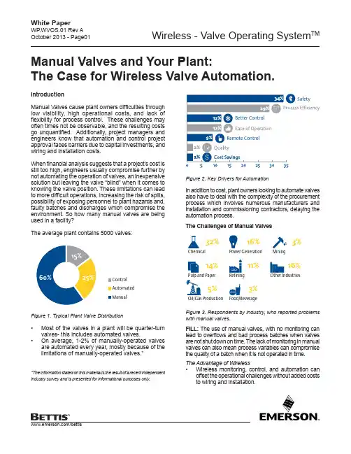
Manual Valves and Your Plant:The Case for Wireless Valve Automation.SafetyBetter ControlRemote ControlFigure 2. Key Drivers for AutomationIn addition to cost, plant owners looking to automate valves also have to deal with the complexity of the procurement process which involves numerous manufacturers and installation and commissioning contractors, delaying the automation process.The Challenges of Manual Valves Problems with Manual ValvesChemical32%Power Generation16%Pulp and Paper14%Refining11%Oil/Gas Production5%3%Mining3%Other Industries16%Figure 3. Respondents by industry, who reported problems with manual valves.FILL: The use of manual valves, with no monitoring can lead to overflows and bad process batches when valves are not shut down on time. The lack of monitoring in manual valves can also mean process variables can compromise the quality of a batch when it is not operated in time.The Advantage of Wireless• Wireless monitoring, control, and automation canoffset the operational challenges without added costs to wiring and installation.IntroductionManual Valves cause plant owners difficulties through low visibility, high operational costs, and lack of flexibility for process control. These challenges may often times not be observable, and the resulting costs go unquantified. Additionally, project managers and engineers know that automation and control project approval faces barriers due to capital investments, and wiring and installation costs.When financial analysis suggests that a project’s cost is still too high, engineers usually compromise further by not automating the operation of valves, an inexpensive solution but leaving the valve “blind” when it comes to knowing the valve position. These limitations can lead to more difficult operations, increasing the risk of spills, possibility of exposing personnel to plant hazards and, faulty batches and discharges which compromise the environment. So how many manual valves are being used in a facility?The average plant contains 5000 valves:Control Automated ManualFigure 1. Typical Plant Valve Distribution• Most of the valves in a plant will be quarter-turn valves- this includes automated valves.•On average, 1-2% of manually-operated valves are automated every year, mostly because of the limitations of manually-operated valves.**The information stated on this material is the result of a recent independent industry survey and is presented for informational purposes only.• Access to real-time monitoring and feedback can provide a valve’s specific position in relationship to the process’ fill activity.• Control room and batch operators can use integrated control logic to automate process and attain batch accuracy.FLUSH: Spills can result from manual flush valves left inthe open position or drain valves not set properly, leading to various process or environmental issues. Discrete valves controlled with a solenoid alone is not as effective as integrating continuous feedback of the valve position. Increase Plant and Environmental Safety with Wireless • Wireless enables fast operation and status feedback.• Determination of valve status in real time allows plant operators to make critical decisions to avoid environmental spills before they occur.DRAIN: Delays in processing caused by waiting for your plant personnel to manually operate or report the status of your drain valves can be cumulative.Improve Plant Efficiency with Wireless• Wireless automation cuts back on lost time and costs by monitoring and implementing your operations from the safety and convenience of your control room.• Wireless reduces the time and cost associated with sending an operator to manually operate a valve. TRANSFER or DUMP: Unwanted variables in the process caused by lack of automation feedback and mechanical switch issues reduce quality and compromise operations and batches. When timing is critical, the risks are even higher. Reduce uncontrolled variables caused by manual operation delays and unreported faulty mechanical operation without increasing installation and maintenance costs with wireless valve automation.Improve Product Consistency and Batch Quality with Wireless• Valve operations can be executed with precise timing reducing variables and increasing batch quality• Determine faulty valves immediately before critical process operations are executed.Traditional ApproachT o fully automate a valve and actuator package, one requires a solenoid, limit switches, input/output points, wi ring, labor, and engineering and procurement capabilities. Lack of standardization arising from multiple vendor components leads to future maintenance issues from ownership of parts replacements, to multiple operation and maintenance standards.Emerson’s wireless solution for valve automation essentially combines solenoid functionality with limit switch feedback into an integrated wireless package further minimizing automation component requirements.Benefits Derived from a Wireless PackageWorker Safety– Wireless control means no more climbing ladders or accessing difficult locations on-site during bad weather or difficult situations.Improve Worker Efficiency– Plant personnel will spend less time moving around operating and monitoring valves. Higher Production Efficiency – Better response time, less downtime, spills and clean up means more time focused on production efficiencies.Reduce Lost Batches – Closed loop control means no human error or lapses from open loop control.Protect the Environment – Incidents that harm the environment cost money and harm a plant’s reputation. Emer son’s wireless Valve Operating System TM (VOS) and Automated V alve Package (A VP) address these challenges. By combining a 4300 series wireless controller, actuator, accessories (for VOS) and valve (for AVP) as a complete kit, Emerson creates value by simplifying the entire procurement process. VOS and AVP assemblies can be installed on-site as a complete unit, fully documented and ready for use. Make the most out of your plant operations today. Visit our VOS and AVP Solutionshere.About the AuthorsDexter Huerto is an Assistant Marketing Manager for Emerson’s Valve Automation for Asia Pacific Region and Charles Khalid S. Rico is a T echnical Writer forValve Automation MARCOM.HandwheelMounting KitMounting KitMounting KitActuatorValve ValveValveControllerWireless - Valve Operating SystemTMWhite PaperWP .WVOS.01 Rev AOctober 2013For complete list of sales and manufacturing sites, please visit/actuationtechnologieslocations or contact us at **************************************World Area Confi guration Centers (WACC) offer sales support, service, inventory and commissioning to our global customers. Choose the WACC or sales offi ce nearest you:NORTH & SOUTH AMERICA 19200 Northwest Freeway Houston TX 77065USAT +1 281 477 4100Av. Hollingsworth325 Iporanga Sorocaba SP 18087-105BrazilT +55 15 3413 8888ASIA PACIFICNo. 9 Gul Road#01-02 Singapore 629361T +65 6777 8211No. 1 Lai Yuan RoadWuqing Development Area Tianjin 301700P. R. ChinaT +86 22 8212 3300MIDDLE EAST & AFRICA P. O. Box 17033Jebel Ali Free Zone DubaiT +971 4 811 8100P. O. Box 10305Jubail 31961Saudi ArabiaT +966 3 340 865024 Angus CrescentLongmeadow Business Estate East P.O. Box 6908 Greenstone1616 Modderfontein Extension 5South AfricaT +27 11 451 3700EUROPEHolland Fasor 6Székesfehérvár 8000HungaryT +36 22 53 09 50Strada Biffi 16529017 Fiorenzuola d’Arda (PC)ItalyT +39 0523 944 411/bettis©2018 Emerson. All rights reserved.The Emerson logo is a trademark and service mark of Emerson Electric Co. Bettis TM is a mark of one of the Emerson family of companies. All other marks are property of their respective owners.The contents of this publication are presented for information purposes only, and while every effort has been made to ensure their accuracy, they are not to be construed as warranties or guarantees, express or implied, regarding the products or services described herein or their use or applicability. All sales are governed by our terms and conditions, which are available on request. We reserve the right to modify or improve the designs or specifications of our products at any time without notice.。
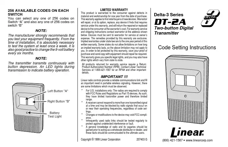
256 AVAILABLE CODES ON EACH SWITCHYou can select any one of 256 codes on Switch “A” and also any one of 256 codes on switch “B”NOTE:The manufacturer strongly recommends that you test your equipment frequently. From the time of installation, it is absolutely necessary to test the system at least once a week. It is also good practice to change the 9-volt battery every six months.NOTE:The transmitter transmits continuously with button depression. An LED lights during transmission to indicate battery operation.LIMITED WARRANTYThis product is warranted to the consumer against defects inmaterial and workmanship for one year from the date of purchase.This warranty applies to first retail buyers of new devices. Warrantorwill repair, or at its option, replace, any device it finds that requiresservice under this warranty, and will return the repaired or replaceddevice to the consumer at the warrantor’s cost. For warranty serviceand shipping instructions contact warrantor at the address shownbelow. Devices must be sent to warrantor for service at owner’sexpense. The remedies provided by this warranty are exclusive.Implied warranties under state law are to the one year period of thiswritten warranty. Some states do not allow limitations on how longan implied warranty lasts, so the above limitation may not apply toyou. In order to be protected by this warranty, save your proof ofpurchase and send copy with equipment should repair be required.This warranty gives you specific legal rights, and you may also haveother rights which vary from state to state.All products returned for warranty service require a ReturnProduct Authorization Number (RPM). Contact Linear TechnicalServices at 1-800-421-1587 for an RPA# and other importantdetails.IMPORTANTLinear radio controls provide a reliable communications link and fillan important need in portable wireless signaling. However, thereare some limitations which must be observed.*For U.S. installations only: The radios are required to complywith FCC Rules and Regulations as Part 15 devices. As such,they have limited transmitter power and therefore limitedrange.* A receiver cannot respond to more than one transmitted signalat a time and may be blocked by radio signals that occur onor near their operating frequencies, regardless of code set-tings.*Changes or modifications to the device may void FCC compli-ance.*Infrequently used radio links should be tested regularly toprotect against undetected interference or fault.* A general knowledge of radio and its vagaries should begained prior to acting as a wholesale distributor or dealer, andthese facts should be communicated to the ultimate users.Copyright © 1999 Linear Corporation207403 GDelta-3 SeriesDT-2ATwo-button DigitalTransmitterCode Setting Instructions(800) 421-1587 • Left Button "A" Right Button "B" BatteryTest LightDT-2A TWO-BUTTON TRANSMITTER CODE SETTINGThere are two digital coding switches in the DT-2A transmitter. Code Switch “A” is exposed by removing the battery access cover. It is the coding switch for the left button on the front of the transmitter (Button “A”).Code Switch “B” is the coding switch for the right button on the front of the transmitter (Button “B”). The switch is located behind the back cover of the transmitter. To access Coding Switch “B”, it is necessary to remove the screw located in the middle of the back cover.SETTING CODE SWITCH “A”Before removing the battery access door,loosen battery clip screw and rotate clip away from door. To open the battery access cover and gain access to Coding Switch “A”, lift off the small L-shaped cover by inserting your thumbnail or a small screwdriver under either of the two slots at the edge of the case. The coding switch has eight keys numbered 1-8.To set a code, select any combination of ON or OFF positions for the switch keys numbered 1-8. Use a paper clip or other pointed object (except a pencil or pen) to set the keys on the coding switch. The ON position is when the top of the switch is down.SETTING CODE SWITCH “B”To gain access to Coding Switch “B”, first remove the screw in the middle of the back cover. Remove the back cover to expose the 8-key switch.To set a code, select any combination of ON and OFF positions for the switch keys, in the same manner as described for Coding Switch “A”.CAUTION:It is not advisable to set a code with all keys ON, OFF, or alternating ON and OFF,because these codes are too easy to duplicate.TRANSMITTERS CODE MUST MATCH RECEIVER CODESwitch “A” is designed for use with a garage door opener. The code set to Switch “A” must be identical to the code set in the receiver to be used in conjunction with Push-button “A”Switch “B”, under the back cover is designed for use with less-frequently changed codes,such as a community gate operated by Push-button “B”. The code set into Switch “B”must be identical to the code set in the receiver to be used in conjunction with Push-button “B”.BATTERYCODING SWITCH "A"ROTATE CLIP AWAY FROM BATTERY DOOR587143O FFON6Keys 1, 2, 3, 4, and 6 OFFKeys 5, 7 and 8 ONCODING SWITCH "A"CODING SWITCH "B"REAR VIEW WITHBACK COVER REMOVED TO ACCESS SWITCH "B"。
MASONEILAN21000系列控制阀操作手册(中文版)二○○三年目录调节阀代码注释 (2)1 引言 (3)2 概述 (3)3 拆除 (3)4 安装 (3)5 送气管道 (4)6 阀体拆卸 (4)6.1 螺纹阀芯 (4)6.2 速换阀芯 (5)7 维修/检修 (6)7.1 螺纹基座拆除 (6)7.2 套管拆除 (6)7.3 研磨基座 (6)7.3A 螺纹阀芯…………………………………………………7.3B 速换阀芯…………………………………………………7.4 逻辑双重端阀……………………………………………………7.5 阀芯轴插杆………………………………………………………7.6 包装箱(标准) ……………………………………………………7.7 包装箱(润滑) ……………………………………………………7.8 软基座活塞………………………………………………………8 阀体再组装……………………………………………………………8.1 螺纹微调…………………………………………………………8.2 速换微调…………………………………………………………9 附图……………………………………………………………………模型序号图1尺寸和比率图21 引言在安装、运行和维修该设备之前,应全面审查并理解下列指南。
在整篇文章中,都有安全和警告注意事项,必须严格坚持,否则,会造成严重损坏或者设备失灵。
Masoneilan在非常熟练的服务工程师,他们广泛应用于阀门和部件的运行、维修和检修。
另外,还进行常规的培训计划以培训我们的阀门及仪表的操作、维修和应用的客户服务与仪表人员。
通过你们的Masoneilan代表或者地区办公室,进行这些服务的安排。
在进行维修时,只用Masoneilan的更换部件。
可以通过当地的Masoneilan代表或者地区办公室购买部件。
订购部件时,通常包括检修机组的模型和系列号。
2 概述安装和维修指南应用于Masoneilan 21000系列控制阀的所有尺寸和比率,不管使用的微调类型。
123456789101112131415161718192021222324252627282930R1707-R313233无线智能控制阀343536373812一、功能简介34●电量显示/提示,时钟设置。
5●阀开启时间设置(1分钟-12小时)。
6●自定义按星期(7天)定时控制电磁阀。
7●四组定时时间设置。
8●自定义按时段(3小时-30天设置)控制电磁阀。
9●手动/自动控制电磁阀的打开和关闭。
10●可选择不同口径大小电磁阀。
11●无操作1分钟自动关闭显示,进入休眠模式。
12●警告电量提示下,无法开启电磁阀或自动关闭电13磁阀。
14●远至800米的无线控制让操作更便捷,有效提高15工作效率16●拥有便捷接的收器对接方案,与发射机完成匹配17操作仅需10s。
1819201二、设备的安装与匹配21.电磁阀的安装位置3a)请在冲洗灌溉系统后再安装本电磁阀。
4b)请将电磁阀安装在主阀之后的位置,可在主阀与电磁阀之间5安装过滤器,如有必要请在电磁阀进水口处安装一个可旋转6的活接以便过滤器的安装,在电磁阀出水口位置使用用匹配7的外丝直通与输水管道链接。
892.电池的安装位置10a)用手握住电磁阀上半部分用力向上提,把控制部分从固定圈上11取下。
12b)在取下的控制部分的底部找到锁住的电磁仓,使用螺丝刀打开13电池仓盖。
14c)区分好电磁仓的正负极,保证电池的正负极与仓体内的标识一15致。
16d)正确放置好电池,盖好仓盖,锁上螺丝。
173.G1707-R是一款具备无线功能的电磁阀设备,通过与G1708型号18发射机的配合使用,可以在500米至800米的远距离范围内实19现对电磁阀的远程操控。
配对成功后可以在发射机上对电磁阀的20运行时间、打开/关闭电磁阀、以及打开/关闭电磁阀系统等功能21进行设置。
具体操作方式请参考G1708遥控器的使用说明书。
2223三、 操作详解1 1) 电池安装与低压保护2 先安装一节9V 叠成电池,并显示当前电3 池电量,如果电池欠压,电池符号4 显示空,并显示电磁阀禁止使用图标。
深信服无线控制器使用手册遥控器“开关”键,用于对遥控器的从休眠状态唤醒、控制温控器“打开和“关闭”。
遥控器处于休眠状态时,液晶屏的显示:如果温控器处于“打开”状态,遥控液晶屏显示温度等信息;如果温控器处于“关闭”状态,遥控液晶屏什么都不显示。
唤醒遥控器:按下遥控器“开关”键,当听到遥控器蜂鸣器“嘀一”的一声时,说明遥控器从睡眠中唤醒,同时液晶屏背光亮。
如果与控制器通讯正常,则可以再听到遥控器蜂鸣器“嘀一”的一声,同时液晶屏右下角出现两个表示收发信号强度的数字;如果与控制器通讯不正常,同时液晶屏右下角出现两个短横杠。
温控器的开关:唤醒遥控器后,每按一次遥控器“开关”键,遥控器把命令发到控制器,如果与控制器通讯正常,温控器在“打开”和“关闭”之间转换一次,同时遥控器的蜂鸣器“嘀一”响两声,控制器蜂鸣器“嘀一”响一声,同时液晶屏右下角出现两个表示收发信号强度的数字;如果与控制器通讯不正常,温控器不能在“打开”和“关闭”之间转换,同时液晶屏右下角出现两个短横杠。
温控器“关闭”时,遥控器液晶屏只显示室温值:温控器“打开”时,遥控器液唤醒遥控器:按下遥控器“开关”键,当听到遥控器蜂鸣器嘀的一声时,说明遥控器从睡眠中唤醒,同时液晶屏背光亮。
如果与控制器通讯正常,则可以再听到遥控器蜂鸣器“嘀一”的一声,同时液晶屏右下角出现两个表示收发信号强度的数字;如果与控制器通讯不正常,同时液晶屏右下角出现两个短横杠。
温控器的开关:唤醒遥控器后,每按一次遥控器“开关”键,遥控器把命令发到控制器,如果与控制器通讯正常,温控器在“打开”和“关闭”之间转换一次,同时遥控器的蜂鸣器“嘀一”响两声,控制器蜂鸣器“嘀”响声,同时液晶屏右下角出现两个表示收发信号强度的数字;如果与控制器通讯不正常,温控器不能在“打开”和“关闭”之间转换,同时液晶屏右下角出现两个短横杠。
温控器“关闭”时,遥控器液晶屏只显示室温值:温控器“打开”时,遥控器液晶屏所有项目正常显示。
一种无线控制的仿真阀门及其使用方法哇塞,今天要给大家介绍一种超厉害的无线控制的仿真阀门呀!这可不是一般的玩意儿哦。
你看,这个仿真阀门就像是一个神奇的开关,它可以在你看不到的地方,默默地工作着,却能给你带来巨大的便利。
它不需要你用手去拧啊转啊,只需要通过无线信号,就可以轻松地控制它啦。
想象一下,你在一个很大的工厂里,有好多管道和设备,要是一个个去手动操作阀门,那得多累啊,而且还容易出错呢。
但是有了这个无线控制的仿真阀门,你就可以坐在办公室里,动动手指,就像玩手机游戏一样,轻松地控制各个地方的阀门开关啦。
它的使用方法也超级简单呢。
首先,你得有一个能发送无线信号的设备,比如手机或者专门的遥控器。
然后,把这个设备和仿真阀门进行配对,就像交朋友一样,让它们认识彼此。
一旦配对成功,你就可以在设备上操作啦。
比如说,你想让阀门打开,就点击打开的按钮,阀门就会乖乖地打开啦。
你想让它关闭,那就点击关闭的按钮,它就会马上执行你的命令哦。
这多方便啊,多高效啊!就好像你有了一个听话的小助手,随时听候你的差遣。
而且啊,这个仿真阀门的精度还特别高呢,可以精确地控制流量和压力,保证你的生产过程或者生活需求都能得到完美的满足。
它的适应性也很强哦。
不管是在高温的环境下,还是在寒冷的地方,它都能稳定地工作,不会因为环境的变化而出现故障。
这就像是一个坚强的战士,无论面对什么样的困难和挑战,都能勇往直前,坚守自己的岗位。
它还特别耐用呢,不需要你经常去维护和修理。
不像有些设备,用不了多久就出问题了,得花时间和精力去照顾它。
这个仿真阀门啊,就只管好好工作就行啦,真的是让人省心又省力。
总之,这种无线控制的仿真阀门真的是太棒啦!它给我们的生活和工作带来了极大的便利和效率,难道你不想拥有一个吗?。
遥控控制阀操作方法
遥控控制阀的操作方法可以分为以下几个步骤:
1. 准备工作:
- 确保遥控器上的电池电量充足,避免影响信号传输。
- 确认遥控器与阀接收器之间的信号连接正常,可通过测试按下遥控器的任意按钮,观察阀是否有响应。
2. 调整遥控器信道:
- 遥控器通常有多个信道可供选择,确保遥控器与阀接收器处于相同的信道,避免干扰或误操作。
3. 开关阀门:
- 使用遥控器上的开关按钮,通过无线信号发送开启或关闭阀门的指令。
- 按下“开”按钮,阀门将打开,液体或气体可以通过阀门流入管道或设备。
- 按下“关”按钮,阀门将关闭,液体或气体将停止流入管道或设备。
4. 调整阀门状态:
- 部分遥控控制阀还可以调整阀门的状态,如调节阀门的流量或压力等。
- 可根据遥控器上的按钮或旋钮,发送相应的指令来调整阀门状态。
5. 其他功能:
- 一些遥控控制阀还具备其他功能,如定时开关、温度控制、自动化等。
根据具体设备的功能,可以通过遥控器上的相应按钮进行设置和操作。
需要注意的是,操作方法可能因不同品牌或型号的遥控控制阀而有所差异,建议在使用前仔细阅读产品说明书,或咨询相关专业人士或售后服务人员,以确保正确的操作方法。
一、上海湖泉普通防爆电动截止阀4G无线控制电动阀门系统方案本控制可通过远程控制、现场控制、总线型集中控制三种控制方式。
电动执行器控制模块接收到远程控制室的控制信号,经光电隔离防抖处理后传输给主控CPU。
CPU实时监测采集执行器状态信号,控制电机传动被控阀门,通过高精度电位器或对值编码器,不断实时采集阀门位置信号,通过现代工业控制软件算法,实现对阀门的精确控制。
同时将实时数据传送给远程控制室。
电动执行器控制模块原理先进、功能全面、长期稳定可靠、集成度高、发热量小、装卸方便、维护简单。
可通过红外遥控器或操作面板按键对其进行非侵入式的快速设置。
二、上海湖泉普通防爆电动截止阀4G无线控制电动阀门具有以下优点1.流体阻力小,其阻力系数与同长度的管段相等。
2.结构简单、体积小、重量轻。
3.紧密可靠,目前闸阀的密封面材料广泛使用塑料、密封性好,在真空系统中也已广泛使用。
4.操作方便,开闭迅速,从全开到全关只要旋转90°,便于远距离的控制。
5.维修方便,闸阀结构简单,密封圈一般都是活动的,拆卸更换都比较方便。
6.在全开或全闭时,闸体和阀座的密封面与介质隔离,介质通过时,不会引起阀门密封面的侵蚀。
7.适用范围广,通径从小到几毫米,大到几米,从高真空至高压力都可应用。
球旋转90度时,在进、出口处应全部呈现球面,从而截断流动。
一、上海湖泉普通防爆电动截止阀4G无线控制电动阀门方案说明:1、每台电装有个无线模组,然后统一连接到云端服务器,可通过有外网的电脑与手机移动设备监视与控制每台电装2、每台电装要有个无线天线出来。
阀门电动执行器应用方案一、上海湖泉普通防爆电动截止阀4G无线控制电动阀门系统方案本控制可通过远程控制、现场控制、总线型集中控制三种控制方式。
电动执行器控制模块接收到远程控制室的控制信号,经光电隔离防抖处理后传输给主控CPU。
CPU实时监测采集执行器状态信号,控制电机传动被控阀门,通过高J度电位器或J对值编码器,不断实时采集阀门位置信号,通过现代工业控制软件算法,实现对阀门的J确控制。
NW—MCV无线测控一体电动阀使用说明书北京新水源景科技股份有限公司2016年6月注意事项:运输存贮无线测控一体电动阀产品在运输的过程中要做好防振措施,安装的过程中要做到轻拿、轻放,防止外力引起的壳体、太阳能电池板、电子元件的损坏。
为防止非法开拆无线测控一体电动阀,无线测控一体电动阀出厂前在固定孔处均已做防拆处理,非经本公司正式授权,任何人不得拆开,以免影响产品的质保。
无线测控一体电动阀采用太阳能供电方式,在安装位置选取时要保证太阳能板阳光照射,严禁有障碍物遮挡太阳能板。
无线测控一体电动阀上行采用扩频小无线方式,在网关安装时应远离空调压缩机、变压器、通讯线缆等,避免被金属物体包围。
冬季需要拆除存放,做好与实际安装位置的记录登记,同时对阀门进行清理养护,按序排放。
一、概述NW—MCV无线测控一体电动阀是智能灌溉系统中的一款产品,智能灌溉系统由管理中心、智能网关、无线测控一体电动阀、智能墒情仪组成。
无线测控一体电动阀采用太阳能配合聚合物锂电池供电,无需架设繁杂的专用供电线缆,节省传统灌溉所需的架设成本。
无线测控一体电动阀适用于大块农田、园林绿化、高尔夫球场等室外灌溉场合,该系统根据田间墒情状况可实现自动,半自动,手动灌溉。
NW—MCV无线测控一体电动阀是北京新水源景科技股份有限公司专利产品,通过电子产品质量检测。
二、主要技术参数1、工作电源:采用太阳能电池板配合可充电大容量聚合物锂电池供电2、静态功耗:≤20uA。
3、最大功耗:≤500mA。
4、待机时间:≥20天。
5、上行通讯接口:无线射频方式,≥2000m(空旷地带)。
6、阀门动作执行时间:开关状态切换≤25s。
7、外部传感器:1路压力流量一体式传感器,采集流量和管网压力。
8、工作耐压≤0.6MPa9、工作温度:-20℃~+55℃。
10、相对湿度:≤95%。
11、压损:≤0.01MPa12、防护等级:IP65。
三、安装要求1、无线测控一体电动阀应无遮挡水平安装,以保证太阳能电池板对锂电池正常充电。
i H-1607无线设备操作说明
(总3页)
-CAL-FENGHAI.-(YICAI)-Company One1
-CAL-本页仅作为文档封面,使用请直接删除
iH-1607 无线设备操作说明
iH-1607无线单防区地址模块采用稳定可靠的433频率,无线距离空地300-500米通过中继无线距离最远可达3公里。
无线单防区地址模块iH-1607配套可使用系统设备
无线主机AL-IH16、AL-IH16G 无线汇集器模块 AL-IHLC08P
无线信号中继器 AL-IH1609 无线警号 AL-629 设备系统设置由8位地址码开关设定,防区分配由6位地址码开关设定,同一系统内主机、探测器、转发器、地址模块、无线信号中继器的8位地址码必须一致,6位防区地址拨码对应防区拨码表来设置。
(主机与无线汇集器、无线信号中继器都只有8位系统码,无线探测器、转发器、无线单防区地址模块有8防系统码开关,有6位防区地址码开关).
防区地址设置拨码表(无线主机同一防区可设置两个不同地址的探测器):。
无线阀控水表热水表安全操作及保养规程1. 引言随着科技的不断进步,无线阀控水表热水表逐渐取代传统的热水表,成为现代生活中不可或缺的设备之一。
为了确保无线阀控水表热水表的正常运行和安全使用,本文将介绍相关的操作注意事项和保养规程。
2. 安全操作指南2.1 正确安装•在安装无线阀控水表热水表时,需要选择平稳、干燥的地面,并确保安装区域通风良好。
•确保无线阀控水表热水表与管道连接紧密,避免漏水现象的发生。
•在安装前,务必关闭水源,避免因操作不当导致水流造成损坏。
2.2 准确操作•在操作无线阀控水表热水表时,务必按照使用说明书上的指示进行操作,避免操作不当导致设备故障。
•避免将非指定物体放置在无线阀控水表热水表上,以免影响设备的正常工作。
•关注无线阀控水表热水表的工作状态,及时发现异常情况,并及时处理。
•使用无线阀控水表热水表时,要注意控制水温,避免水温过高导致烫伤。
•定期检查和清理无线阀控水表热水表的加热元件,避免因积灰或其他原因导致加热不均匀,进而影响使用安全。
3. 保养规程3.1 清洁保养•定期清洗无线阀控水表热水表的外观,避免灰尘和污垢的积累。
•使用软布沾水擦拭热水表的表面,避免使用硬物擦拭,以免刮伤表面。
3.2 定期维护•定期检查无线阀控水表热水表的阀门和管道连接是否紧固,如发现松动应及时处理。
•检查无线阀控水表热水表的显示屏和按键是否正常工作,如发现异常应及时联系售后人员进行维修或更换。
3.3 定期更换电池•无线阀控水表热水表需要使用电池供电,定期检查电池寿命,如发现电池电量不足,应及时更换新电池,避免因电池耗尽导致设备无法正常使用。
•在寒冷的季节,要特别注意无线阀控水表热水表的管道是否有冻结的风险,如有必要可采取相应的保温措施,避免冻结造成设备损坏。
4. 总结无线阀控水表热水表作为现代生活中不可或缺的设备,我们应当重视其安全操作和保养。
通过正确安装和操作,定期进行保养维护,我们可以延长设备的使用寿命,确保其正常运行并最大程度上保障使用者的安全。
123456789101112131415161718192021222324252627282930R1707-R313233无线智能控制阀343536373812一、功能简介34●电量显示/提示,时钟设置。
5●阀开启时间设置(1分钟-12小时)。
6●自定义按星期(7天)定时控制电磁阀。
7●四组定时时间设置。
8●自定义按时段(3小时-30天设置)控制电磁阀。
9●手动/自动控制电磁阀的打开和关闭。
10●可选择不同口径大小电磁阀。
11●无操作1分钟自动关闭显示,进入休眠模式。
12●警告电量提示下,无法开启电磁阀或自动关闭电13磁阀。
14●远至800米的无线控制让操作更便捷,有效提高15工作效率16●拥有便捷接的收器对接方案,与发射机完成匹配17操作仅需10s。
1819201二、设备的安装与匹配21.电磁阀的安装位置3a)请在冲洗灌溉系统后再安装本电磁阀。
4b)请将电磁阀安装在主阀之后的位置,可在主阀与电磁阀之间5安装过滤器,如有必要请在电磁阀进水口处安装一个可旋转6的活接以便过滤器的安装,在电磁阀出水口位置使用用匹配7的外丝直通与输水管道。
892.电池的安装位置10a)用手握住电磁阀上半部分用力向上提,把控制部分从固定圈11上取下。
12b)在取下的控制部分的底部找到锁住的电磁仓,使用螺丝刀打13开电池仓盖。
14c)区分好电磁仓的正负极,保证电池的正负极与仓体的标识一15致。
16d)正确放置好电池,盖好仓盖,锁上螺丝。
173.G1707-R是一款具备无线功能的电磁阀设备,通过与G1708型号18发射机的配合使用,可以在500米至800米的远距离围实现对电19磁阀的远程操控。
配对成功后可以在发射机上对电磁阀的运行时20间、打开/关闭电磁阀、以及打开/关闭电磁阀系统等功能进行设21置。
具体操作方式请参考G1708遥控器的使用说明书。
2223三、 操作详解1 1) 电池安装与低压保护2 先安装一节9V 叠成电池,并显示当前电3 池电量,如果电池欠压,电池符号4 显示空,并显示电磁阀禁止使用图标。
此5 时手动和自动打开电磁阀都无效。
表示电6 磁阀此时不能使用。
7 89 2) 设置系统时钟与星期10 在菜单时钟图标显示,小时闪烁,再按“+”11 按钮,小时数字加,再按“-”按钮,小12 时数字减。
调到与当前实际的时间为止,13 然后再按选择按键,光标调到分钟位置并14 闪烁,再按“-”按钮,分钟数字减小,15 再按“+”按钮,分钟数字加,直到与当16 前实际分钟为止,再按选择按钮,光标调17 到星期位置并闪烁,再按“+”按钮,或18 者按“-”按钮,最后再按菜单键确定。
19 这样系统时间与星期就设置好了 20 21 。
2223 3) 设置系统灌溉时间24按菜单键转到图标位置,默认为525分钟,最大12小时。
按选择键按钮,光26 标跳到小时并闪烁,按“+”键小时增加127 小时,按“-”按钮小时减少1小时;再28 按选择键按钮,光标跳到分钟并闪烁,按29 “+”按钮,分钟增加1分钟,按“-”按30 钮,分钟减小1分钟。
自动保存起来。
如31 下图所示。
在设置过程中,如果设置的时32 间小于1分钟,也就是等于0的时候,界33 面将提示错误警告,用户需要再次设置灌34 溉时间大于0分钟35图 1图 2图 31 4) 设置灌溉日期(按每周设置)和42 组定时时间设置3按菜单键转到如图4所示,再按选择4 键进入星期选择;如选择按菜单键则跳过5 星期模式。
67 按选择键后,电池图标旁的星期标识闪烁8 为待定状态,按“+”为选择确定,按“-”9 为取消;确定后当前光标不在闪烁且为显10 示状态;取消后当前位置光标消失。
可通11 过选择键来进行一周七天的灌溉日期设12 置,方法同上。
星期设置好后再按菜单键13 进入电磁阀定时时组设置。
14 15 16 1718 刚进入第一组时设时屏幕显示为OFF 。
此19 时按下选择键OFF 开始闪烁,再按加减按20 键进入第一组时间设置。
如图6所示,此21 时按选择键光标跳到小时位置并闪烁,按22 “+”或者“-”键小时增加或者减小。
调23 整好小时刻度后再按选择键,光标跳到分24 钟位置并闪烁,按“+”或者“- ”分钟25 增加或者减小。
26 27 2829 第一组时间调好后按菜单键进入第二组30 时间设置,此时屏幕依旧显示OFF ,按下31 选择按键OFF 闪烁,再按加减按键进入第32 二组时间设置,设置方法同第一组一样,33 第三组,第四组也一样。
设置完毕后系统34 就会按照以上设置的星期及时间段进行35 控制电磁阀。
如要取消某时间组,只需把36 此组时间通过加减按键调整至24:00状37 态下即可,此时屏幕上出现OFF ,表示此38 组时间取消。
3940图 4图 5 图 6图 71 25) 设置灌溉日期(按每月设置)。
12 按菜单键转到循环图标位置,屏幕如3 图8显示。
按下选择键OFF 闪烁,此时选4 择按下“+”键进入最小初始时间“3小时”5 开始设置;如果选择按“-”则从最高的6 时间“30天”开始设置。
设置的循环时7 间以3…6…12…24小时增加,24小时后8 以每天为单位增加。
调好时间后按菜单键9 进入灌溉时间设置。
灌溉时间对应系统时10 间。
11 1213 图9界面下,按选择键,小时闪烁,按“+”14 或者“-”键对小时增加或者减小,调整15 好小时参数后再按选择键,分钟闪烁,依16 旧通过加减来调节分钟参数。
设置完毕后17 按菜单键回到时钟显示界面,按月模式开18 始生效。
需要注意按周模式与按月模式19 不能同时开启。
202122 6) 手动打开电磁阀23 在时钟显示界面按橙色按钮,手动打开电24 磁阀并进入倒计时状态,倒计时按已设定25 好的灌溉运行时间为准。
比如图10设置26 的运行时间为五分钟,那么系统就会从五27 分钟开始倒计时。
自动倒计时结束后系统28 主动关闭电池阀,倒计时期间也可以手动29 关闭电磁阀。
此时同样也能通过G1708无30 线遥控器对电磁阀进行打开/关闭的操31 作。
32 3334 7) 手动禁用电磁阀35 长按(3秒)x 按钮,禁止启用电磁阀,36 此时手动和自动开启电磁阀功能都失效,37 如图11。
在设置过程中可先开启此功能手38 动禁用电磁阀,等设置完毕再恢复,长按39 (3秒)X 按钮,恢复电磁阀功能。
.4041图 8 图 9图 101 23 三、 欠压保护4 56 当电池电量消耗殆尽,电池电压过低时,7 电池图标显示为空,出现如下图12所示,8 系统自动关闭手动控制及自动控制功9 能。
电磁阀也处于关闭状态。
此时需要10 您及时更换电池,以保证电磁阀的正常11 运行。
12 13 14 15 1617 四、 程序退出保护 181920 如果用户在操作过程中忘记退出,系统21 会在无操作的一分钟后自动回到时钟22 界面,以保证程序的正常运行。
23 24 25 26 。
27 28 29 30 3132 五、 维护建议33 1) 如果长时间不适用控制阀,请把电池取出。
3435 2) 电磁阀系统会在电池断电时主动关闭,在更换电池时,已设定的程36 序数据会保留30s 不会丢失。
3738 3) 在控制阀上游安装一个过滤器,每隔几个月清洗1次.在没有过滤39 器的系统中使用控制阀将导致故障的发生发生。
40图 12图 13图 111234567产品保修政策89➢保固服务仅限于经合法销售通路购买本公司产品的消费者。
10➢保固期间以自消费者购买日为计算七点,按国家三包细则规定年限的保11固期限,执行本公司的保修承诺12➢为确保客户权益,购买者请保留产品三包凭证或购买发票13➢购买时必须请销售商在三包凭证上加盖店章,且填入销售日期;14➢产品外箱序号贴纸粘贴至三包凭证以资证明;15➢若三包凭证卡未包含以上容,视为无效,则以机器出厂日期为准16➢保固围指正常状况下无法使用以及在制造、材质、组装上的瑕疵。
17➢产品在保修期间提供(零件、检修工资)免费保固服务。
18➢维修后更换的消耗零件,保固期限为一个月。
19➢本保修条款仅适用于中华人民国大陆围(不包含港澳台地区)。
20➢购买于三包退换货期限产品发生性能故障的请至原经销商处理21➢其他详细资料请咨询客服专线,售后服务中心具有产品的解释权123456产品保修卡789客户名称:产品型号:101112联系:购买日期:131415产品机型:经销商:1617181920212223经销商代理:252627282930313233343536373839.. ..12345678910. . . .。