多功能水泵控制阀使用说明书模板
- 格式:doc
- 大小:10.12 MB
- 文档页数:9
J745X-D 10 16 25 40 64多功能水泵控制阀使用说明书安装使用时请详细阅读本说明书冈野集团阀门科技有限公司多功能水泵控制阀细分为:A类:双进双出型(DN400口径以上)B类:深井泵型(DN200以下带排气阀,大于或等于DN200建议加装排气阀)C类:立式安装型(带弹簧)D类:流量调节型(带调节丝杆)E类:标志杆型(带行程开关)F类:全行程数显装置型(带数显装置)一、用途安装在市政、建筑、钢铁、冶金、石油、化工、煤气(天然气)、食品、医药、矿山、电站、核电、水利及灌溉等领域的取水、送水、加压、潜水、污水泵房及石油、化工流体的输送系统中,融电动阀、止回阀和水锤消除器三种设备的功能于一体,能有效地提高系统安全可靠性,满足系统自动化控制要求。
二、特点1、安全可靠性高,具有速闭、缓闭以及吸能腔三种消除水锤措施,而且动作完全联锁,不会产生误动作。
2、无需操作控制,当水泵启停时,巧妙地利用阀门前后介质的压力变化来控制动力,使阀门自动按水泵操作规程的要求进行动作。
3、无需专业调试,阀门动作不受水泵扬程及流量变化的影响,适应范围广。
4、基本无需维修,寿命长。
5、节能效果明显,利用进口端的压力进入膜片下腔支撑膜片压板及阀杆的重量,阻力损失小。
三、技术参数1、公称压力:1.0MPa、1.6MPa、2.5MPa、4.0MPa、6.4MPa、10.0MPa2、最低动作压力:0.05MPa3、适用介质:原水、海水、污水、油品4、适用温度:0 ~ 80℃5、缓闭时间:3 ~ 120S(可调节)6、水锤峰值:≤1.3倍水泵出口额定压力7、水泵最高反转速度:≤1.2倍水泵额定转速8、膜片疲劳弯曲:120万次无破损四、结构(图一:结构示意图)多功能水泵控制阀由主阀和外装附件组成,主阀由阀体、膜片、阀杆组件、阀盖、主阀板、缓闭阀板、膜片座等主要零件组成,外装附件主要有控制阀、过滤器、排气阀、微止回阀、其中微止回阀是特制配件,在其止回方向设有限流孔。
多功能水泵控制阀技术说明多功能水泵控制阀采用现代化的控制技术和先进的电子元器件,通过传感器对水压、水位、温度和流量等参数进行实时监测和采集。
然后,控制系统根据预设的参数和逻辑进行计算和判断,控制水泵的启停和调节水流。
同时,它能够自动检测水泵的运行状态,如功率、电流、电压、温度等,以及故障和报警信息。
通过与人机界面设备的连接,操作人员可以方便地对水泵进行设置、监测和控制。
1.自动化控制:多功能水泵控制阀采用了先进的控制算法和智能化的控制设备,能够实现水泵的全自动控制。
它可以根据实时的水流需求,自动启停水泵,调节水泵的转速和流量,并且可以实现多泵并联控制和备用泵切换。
2.多种控制模式:多功能水泵控制阀具有多种控制模式,如压力控制、流量控制、水位控制等。
用户可以根据实际需求选择不同的模式进行控制。
同时,还可以根据具体情况进行参数设置和自定义控制策略,以满足不同场合和需求的要求。
3.远程监控:多功能水泵控制阀可以与计算机、PLC或SCADA系统进行连接,实现远程监控和控制。
使用者可以通过网络或无线通信设备实时监测和远程控制水泵的运行状态和参数,及时处理故障和报警信息,提高运维效率和管理水平。
4.故障报警和保护功能:多功能水泵控制阀具有丰富的故障报警和保护功能,如过流保护、过压保护、欠压保护等。
在水泵发生故障或异常情况时,它会自动进行报警并采取相应的保护措施,避免进一步损坏设备和系统。
5.节能效果明显:多功能水泵控制阀能够根据实际需求调节水泵的流量和压力,实现节能效果。
通过控制阀的变频调速功能,可以降低水泵的能耗,提高整个系统的运行效率和节能效果。
总之,多功能水泵控制阀是一种集控制、监测、报警和保护于一体的自动化设备,能够实现水泵的全自动控制和远程监控。
它具有多种控制模式、远程监控、故障报警和保护功能等特点和优势,可以满足不同场合和需求的要求,提高水泵系统的稳定性、安全性和节能效果。

多功能水泵控制阀技术说明-标准化文件发布号:(9456-EUATWK-MWUB-WUNN-INNUL-DDQTY-KII多功能水泵控制阀技术性能说明一、用途多功能水泵控制阀安装在市政、建筑、钢铁、冶金、石油、石化、化工、煤气(天然气)、食品、医药、电站、核电、水利及灌溉等领域的取水、送水、潜水、污水泵房及石油、化工流体的输送系统中,与泵机联锁自动控制,一阀兼具电动阀、止回阀和水锤消除器三种设备的功能于一体,具有截止、节流、止回、消除水锤;故障少、关闭严密、消除水泵在停泵、事故停电或阀门关闭时可能发生的水锤时性能可靠等优点,能有效地提高供水安全可靠性,符合给排水工程设备机械化和自动化、远程控制的要求。
当水泵开启和停止时,利用阀门两端的介质及其压力差作为驱动介质和控制动力使阀门动作自动按水泵操作规程要求进行动作。
二、型号、规格、技术参数说明型号: JD745X-10技术参数:1、公称压力:1.0MPa;2、最低动作压力:0.05MPa3、适用介质:原水、污水、清水、循环输水、油品等4、介质温度: 0~80℃;5、缓闭时间:3秒~120秒(可调节);6、水锤峰值:≤1.3倍水泵出口额定压力7、水泵最高反转速度:≤1.3倍水泵额定转速。
8、膜片疲劳弯曲:200万次无破损。
9、泄漏量为零。
10、阀门壳体强度实验压力: 1.5倍公称压力11、阀门密封实验压力: 1.1倍公称压力12、表面处理采用环氧树脂防腐涂料喷涂。
阀门系统组成组成部件说明:序号零件名称序号零件名称1 阀体8 主阀板座2 阀杆9 膜片座3 O型密封圈10 膜片4 膜片压板a、e 控制阀5 阀盖 b 过滤器6 缓闭阀板 c 微止回阀7 主阀板d、f 排空阀设计和制造说明:1)、阀体:法兰与阀体整体铸成。
2)阀盖、膜片座阀盖与膜片座、膜片座与阀体的连接型式采用法兰式。
膜片座与阀体的连接螺栓数量不少于4个。
阀盖与膜片座的法兰为圆形。
法兰密封面的型式采用突面式。

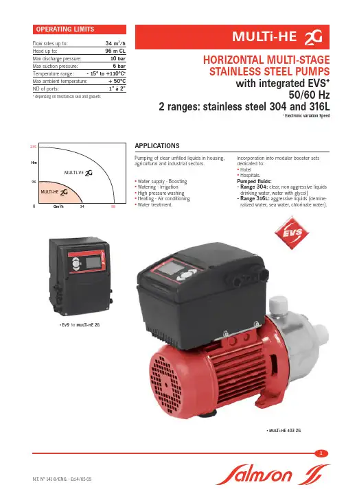
Pumping of clear unfilled liquids in housing,agricultural and industrial sectors.•Water supply - Boosting •Watering - Irrigation •High pressure washing •Heating - Air conditioning •Water treatment.Incorporation into modular booster sets dedicated to:•Hotel •Hospitals.Pumped fluids:- Range 304:clear, non-aggressive liquids drinking water, water with glycol)- Range 316L:aggressive liquids (demine-ralized water, sea water, chlorinate water).Flow rates up to:34 m 3/h Head up to:96 m CL Max discharge pressure:10 bar Max suction pressure: 6 bar Temperature range:- 15°to +110°C*Max ambient temperature:+ 50°C ND of ports:1” à 2”* depending on mechanical seal and gasketsN.T. N°141-8/ENG. - Ed.4/05-05HORIZONTAL MULTI-STAGESTAINLESS STEEL PUMPSwith integrated EVS*50/60 Hz2 ranges: stainless steel 304 and 316L* Electronic Variation Speed23596Qm 3/hHmAPPLICATIONS• MUL Ti-HE 403 2G• EVS * for MUL Ti-HE 2G•Reduction of mechanical and electrical constraints compared toa standard pump:- No more successive starts and stops - flexible use, reduction of hammering and knocking- limiting of starting current- adjustment to installation by precise adjustment of speed and pressure.•Automatic diagnosis to facilitate maintenance.•Reduction in sound levels by adapting pump speed to requirements.•Easy installation and use thanks to simple implementation and operation.•SAVINGS- Optimization of complete product pump + motor + converter guaranteeing energy savings.- une seule pompe couvre une gamme complète de pompes standard.- One contact, one supplier for a complete automatic system.•Smaller booster size thanksto integration of frequency converter in pump.•Hydraulic part- All stainless steel.- Centrifugal multistage with 2 to 6 stages. - Horizontal axis- Suction / Discharge orifices tapped.- Axial suction, radial discharge upwards.- Tightness at shaft passage by standardized mechanical seal.• MotorDry motor, 2 pole equipped with VEV. Winding3- phase:380 to 440 V ±6% Frequency:50 and 60 Hz Insulation class:F (155°C) Protection index:IP 54Electronic speed variation is applied tothe asynchronous motors of the MUL TI-HEcentrifugal pumps.The goal is to regulate the speed of the ACmotor by converting voltageand frequency of the mains inputs from 380to 440 V ±6% at 50 or 60 Hz into a threephase voltage system with variable frequencyand amplitude.The frequency converter then makes itpossible to control the speed of the motor.This simultaneous action on the frequencyand voltage is by means of two mainelements:- a diode rectifier-a pulse width modulatinginverter (MLI).The rectifier is a diode bridge. The ACvoltage conducted through the diode bridgeis converted into a rectified DC voltage.At this stage, to refine the quality of the DCvoltage at the rectifier output, a set ofcapacitors and coils eliminates any residualripple output from the rectifier.In this way, we obtain a smooth DC voltagecalled the “DC bus”.With this development, the inverterdefinitively adjusts the voltage at the outputof the variator to optimize the magnetizingof the motor. The set voltage at the inverterinput is converted again into a variablevoltage by acting as voltage pulses for avariable period of time via the transistors.This principle is referred to as pulse widthmodulation. These transistors are controlledby the micro-controller which activates ordeactivates them so as to vary the frequencyat the variator output.The transistors (IGBT: Insulated Gate BipolarTransistor) therefore operate by switching andact as switches to convert the DC voltageinto a variable voltage.The IGBT switching activation frequencycreates variable voltage and frequencymagnitudes.The frequency must be high toeliminate the noise produced bymagnetization (frequency inaudible to thehuman ear: 8 to 16 kHz).Pump code Nominal flow in m 3/h (to 50 hz/2 pole )Number of stages Stainless S = 304 X = 316LE =O-rings : EPDM (WRAS/KTW)V =O-rings : VITON M13 = 1-phase Mode 1-3M2 = 1-phase Mode 2T = 3-phase 2 = 2 Pole2nd Generation inverterMode 1 / manual modeThe pump is installed in the same way as a MUL TI-H standard pump but offers the possibility of manually adjusting its speed and therefore working through a range of flow.Pressure curves according to the needs of the installation.From the required Q/H point,the operating frequency can bedetermined by means of a curve plotter (see the following pages).MUL Ti-HE 402- SE - T/2- 2GRange Stainless 304Stainless 316L2/4/8/162/4/8Main partsMaterialsnon-aggressive aggressiveliquids liquids Pump casing Stainless 304Stainless 316L Impellers Stainless 304Stainless 316L Cells (stage)Stainless 304Stainless 316L Pump shaft Stainless 316L Stainless 316LMechanical seal Si carbide Tg carbide Carbon Carbon O-rings EPDM*Viton**PlugsStainless 316L Stainless 316L* T°110°C — **T°90°CNB: Stainless 304 (Z6CN18-9)or 316 L (Z2CND17-12)recommended materials offering high resistance to corrosion. Clean conveyed liquids with fibers and containing little sand/silica (max concentration 40 g/m 3).Three operating modes can be chosen according to the application and the need. The user selects the operating mode by touch pad.On delivery, the pump is configured in Mode 1.The information is viewed on a display.05-Filling plug06-Drain/priming plug 07-Pipe supports or collar 08-Strainer09-Storage vessel 10-City water networkHA = suction head HR = discharge headMode with pump alone using pressure regulation. The pump is installed with its pressure sensor which can attached either to the pump or on the discharge pipe.The setpoint pressure is adjusted when the pump is installed by means of the touch pad.Operation: when the real pressure measuredon the sensor drops below the set pressure,the pump starts and controls its speed to achieve the set pressure.The pump stops automatically when it detects that flow is zero or that there is a Mode 2 / automatic pump boost system Mode 3/ use of pump on booster The frequency variation is managed by an external control.Starting, stopping and the speed of rotation of the pump are controlled by a 0-10 V or 4-20 mA input signal.KEY01-Foot valve strainer 02-Pump suction valve 03-Pump discharge valve 04-Non-return valve 05-Filling plug06-Drain/priming plug 07-Pipe supports or collar 08-Strainer09-Storage vessel 10-City water network11- Switch/isolator with fuses 12-Concrete block 14-Pressure sensor kit 15-Vessel16- Vessel isolating valve HA = suction head HR = discharge headMode 1Mode 2 Mode 3OKAdjusting of thefrequency from 30% to 100%OKAdjustingof the setpoint(0 to 100% of thesensor’s rating)Adjustingof ALTi-Esetpoint4-20mA or 0-10V sensor (pressure, temperature, flow rate, etc)• Display- Speed shown on the screen• On/Off-Remote-With button• Display- Displaying of pressure for pressureregulation- Displaying of % for other types ofregulation• On/Off- Remote- With button• Pressure regulation- Adjusting of the setpoint using the buttonsOR- Adjusting of the setpoint via external signal• Other types of regulation- Possibility of adjusting the PID corrector- Choosing of the regulation type(flow rate, temperature, etc)• Display- Displaying of the rotation speed• On/Off- Remote- With buttonThe following functions are integrated into the pump, depending on the modes:- Lit display- Remote on-off or with touch pad - Automatic zero flow detection - Water run-out detection- Reducing of the nominal speed according to the liquid pumped.- Protection from:- short-circuits - circuit overloads - over/under-voltages - excessive temperature - microbreaks - missing phase- Maintenance self-troubleshooting via error code on the display.Maintenance troubleshootingAnalysis is based on parameters such as over/undervoltage, sensor power supply failure or cut cable, short circuit, overload, etc. The pump then indicates any faults through the red LED and an error code shown on the display.• 1.1 to 4 kW unit DisplayControl connectorsSwitches for locking the settings and the setpoint SBM unavailability indicator and SSM fault indicator relayPhase 1 / 2 / 3 + ground power terminal blockL1L2L3PEFault typeInverter behaviour SignalingWaiting time Waiting time Max number of State before stopbefore restartdefaults over 24hFault code LED red Variator Temperature 3 s 5 mn*6E30 E31Flashing Short-circuit Immediate 5 s 6E23Flashing LineOvervoltage ≤5 s 5 s*6E05Flashing Undervoltage ≤5 s 5 s*6E04Flashing Missing phase ≤5 s 5 s*6E06 (E04)Flashing Motor Temperature 3 s 5 mn*6E20 (E26)Flashing Short-circuit Immediate 5 mn*6E23Flashing PumpPump blocked 3 s No 1E10Flashing restart Dry operation < 60 s 1 mn 6E00Flashing OverloadVariable 1 mn 6E01Flashing ExternalIncorrect pump code Immediate No 1E99Flashing restart Cable cut in 5 sNo 1E42Flashing(only w.sensor restart4/20 mA)* If the fault is eliminated10203040%0,00,20,40,60,81,0kW01020304050607080Ql/min Ql/sHm100501,5210,5An ESV (Electronic Speed Variation) pump is represented by a network of curves showing the intermediate performances covered.With speed variation, the power input is adapted to the H/Q need required, resulting in large energy savings.10203016202428323650Qm /hHm405048126080100700,00,20,40,60,81,036912010203040%01020304050607080Qm /hkWmQl/min Ql/sHm100501,5210,50,40,61,02468101210203040506005101520253035404550kW%mHm0,51,01,52,02,52600Qm /hkWm002040608005101520253035404550550,00,51,01,52,02,5024680204060kWmHm50- 1600 0,00,51,01,52,02,524681001020304050600051015202530354812162024283236Qm /hkWm%N.P .S.HQm 3/h Qm /hQl/min Ql/sHm100020003000400500600105a) Electrical- Three-phase 380 V/ 440 V - 50/60 Hz,tolerance ±6%, 2 pole.b) Assembly- Installation in an easily-reached place on suction or load side- Mounting on block or directly on smooth and horizontal surface- Pump attachment by 2 holes for Ø M8studs.Connection to installation by flexible pipe with reinforcing spiral or rigid pipe.c) Conditioning- Pump supplied in cardboard package without connection accessories.FEATURES•Suction kit •Isolating valves•Anti-vibration sleeves•Bladder or galvanized vessel •Anti-hammering vessel•Check valves (with ogive or flap, with spring if operation in Mode 2•Foot valve strainer•Dry running protection (mode 1)•Control pressure sensor kitACCESSORIESSENSOR KITS : MOUNTING ACCESSORY Sensor Kits Modelorder reference item reference 6 bar MUL Ti-HE 403CAPTPRESS 6b 4048063MUL Ti-HE 160210 barMUL Ti-HE 205CAPTPRESS 10b4048064MUL Ti-HE 406 MUL Ti-HE 80353 bd de la République - Espace Lumière - Bât. 6 - 78403 Chatou Cedex FRANCE Tel: +33 (0)1 30 09 82 39 - Fax: +33 (0)1 30 09 82 34 - 。
控制阀F96说明书⽔处理系统⽤多功能控制阀53550(F96B1)53650(F96B3)63550(F96A1)63650(F96A3)73550(F96D1)73650(F96D3)93550(F96C1)93650(F96C3)安装使⽤说明书在使⽤本阀前请详读此说明书,并加以妥善保存以备今后参考之⽤。
0WRX.466.065正式投⼊使⽤前,请填写好下⾯的内容,以备后查程序型号设置(专业⼈员操作)秒,可进⼊型号选择界⾯。
设置型号时,须设置与控制阀体相应的型号。
软⽔器系统配置罐体尺⼨:直径mm,⾼度mm;填装树脂体积L;盐箱容积L;原⽔硬度mmol/L;进⽔压⼒MPa;控制阀型号;编号;排⽔限流圈规格;射流器型号。
进⽔⽔源情况(选择):地下⽔□;地下⽔加过滤器□;⾃来⽔□;其它。
控制阀设定参数●产品采购时,未作特殊说明:63550、63650、73550、73650配套的排⽔限流圈为4#(钻有5个φ8.5的孔),射流器型号为4#(7804)。
⽬录注意事项 (1)⼀、产品概述 (2)1、主要⽤途及适⽤范围 (2)2、产品特点 (2)3、使⽤条件 (5)4、产品结构及技术参数 (6)5、产品安装 (9)⼆、基本设置和使⽤说明 (16)1、控制⾯板功能及其意义 (16)2、基本设置和使⽤ (17)三、应⽤说明 (20)1、⼯作流程 (20)2、控制电路功能及连接 (22)A、信号输出端⼝ (23)B、互锁 (25)C、泄压端⼝ (26)D、远程控制端⼝ (26)E、双(多)阀,同时供⽔,分别再⽣ (26)F、双(多)阀单流量计,同时供⽔,顺序再⽣ (27)G、浮动床进⽔泵与软⽔泵 (27)3、产品系统配置及流量特性 (28)4、参数计算及取值 (32)5、参数查询和设置 (34)6、试运⾏ (38)7、常见故障及其排除⽅法 (40)8、组件及零部件编号 (43)四、保修说明 (52)●为确保产品安装后的正常使⽤,请在使⽤前让专业的安装或维修⼈员确认。
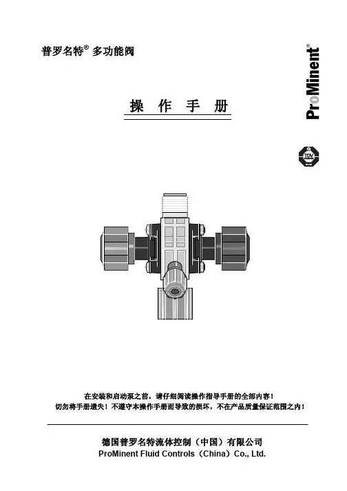
普罗名特® 多功能阀操 作 手 册P r o M i n e n t®目录1结构设计 (1)2功能描述 (1)3使用范围 (2)4安装 (3)5操作 (3)6技术参数和订货号 (4)1结构设计多功能阀通过弹簧负载的隔膜实现其每个功能。
阀的卸压机构具有保持压力恒定以及卸压的功能。
2功能描述功能- 敞口计量时,产生一个稳定的背压。
顺时针方向旋转黑色星状旋钮(1)可取消此项功能。
- 防止投加点产生负压时从药桶中抽出药液。
顺时针方向旋转黑色星状旋钮(1)可取消此项功能。
注意背压阀不能用作完全密封截止阀。
1 2如果不向投加点输送计量介质或泵的待机时间长,则必须在泵的吸入端另外安装截止阀。
- 启动泵时克服压力辅助引液,而不必松开排液管线。
旋动红色星状按钮(2)实现此项功能。
注意— 由于阀工作时,系统的药液可能通过旁路管线流出,故必须在投加点安装单向止回阀。
- 当相关系统处于待机状态(例如维修)时,用于给计量管线卸压。
- 用作溢流阀,防止由计量泵产生的不允许的超压。
通过旁路管线溢流,自动执行溢流功能。
3 使用范围指定用途用于在关闭截止阀时,防止因计量泵产生的不容许的超压。
必须连接旁路管线。
非指定用途不能用于防止除计量泵以外的其它原因产生的不容许的超压。
此阀不能用作截止阀。
如果压力系统没有安装注射阀,不能使用此阀。
如系统没有安装旁路溢流管线,不能使用此阀。
4安装安全注意事项投加点必须安装单向止回阀,因为阀工作时系统中的计量介质通过旁路可能会产生回流。
机械/液压安装多功能阀直接旋到泵的压力连接端上,阀可以360°任意转动。
使用连接用具或GF螺纹配件,将计量管线或软管固定在泵的出口端上。
出厂前,EPDM材质的O型圈已安装在泵出口的凹槽内。
对于不适用EPDM材质的情况,建议安装Viton B型的O型圈,该O型圈(棕色)同阀一起供货。
使用卡环和管接螺母紧固旁路管线,并引回药桶。
因为阀在接近于开启压力时会出现少量的溢流,故必须始终接通旁路管线。
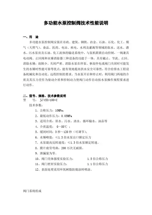
多功能水泵控制阀技术性能说明一、用途多功能水泵控制阀安装在市政、建筑、钢铁、冶金、石油、石化、化工、煤气(天然气)、食品、医药、电站、核电、水利及灌溉等领域的取水、送水、潜水、污水泵房及石油、化工流体的输送系统中,与泵机联锁自动控制,一阀兼具电动阀、止回阀和水锤消除器三种设备的功能于一体,具有截止、节流、止回、消除水锤;故障少、关闭严密、消除水泵在停泵、事故停电或阀门关闭时可能发生的水锤时性能可靠等优点,能有效地提高供水安全可靠性,符合给排水工程设备机械化和自动化、远程控制的要求。
当水泵开启和停止时,利用阀门两端的介质及其压力差作为驱动介质和控制动力使阀门动作自动按水泵操作规程要求进行动作。
二、型号、规格、技术参数说明745X-100-C型号: JD技术参数:1、公称压力:10MPa;2、最低动作压力:0.05MPa3、适用介质:原水、污水、清水、循环输水、油品等4、介质温度: 0~80℃;5、缓闭时间:3秒~120秒(可调节);6、水锤峰值:≤1.3倍水泵出口额定压力7、水泵最高反转速度:≤1.3倍水泵额定转速。
8、膜片疲劳弯曲:200万次无破损。
9、泄漏量为零。
10、阀门壳体强度实验压力: 1.5倍公称压力11、阀门密封实验压力: 1.1倍公称压力12、表面处理采用环氧树脂防腐涂料喷涂。
阀门系统组成组成部件说明:序号零件名称序号零件名称1 阀体8 主阀板座2 阀杆9 膜片座3 O型密封圈10 膜片4 膜片压板a、e 控制阀5 阀盖 b 过滤器6 缓闭阀板 c 微止回阀7 主阀板d、f 排空阀设计和制造说明:1)、阀体:法兰与阀体整体铸成。
2)阀盖、膜片座阀盖与膜片座、膜片座与阀体的连接型式采用法兰式。
膜片座与阀体的连接螺栓数量不少于4个。
阀盖与膜片座的法兰为圆形。
法兰密封面的型式采用突面式。
3)阀杆、缓闭阀板、主阀板缓闭阀板与阀杆连接紧固、可靠。
缓闭阀板与主阀板的密封型式采用金属密封的型式。
水泵控制器的功能介绍说明书尊敬的用户:非常感谢您选择我们公司生产的水泵控制器。
为了更好地使用产品,我们特别制作了详细的功能介绍说明书,希望对您有所帮助。
1. 产品概述本产品是一种用于控制水泵开关的智能化设备,可以根据水位、压力等参数,智能控制水泵的运行,避免了需要人工操作的麻烦和时间浪费,具有非常广阔的应用领域。
2. 功能特点2.1 自动开关水泵本产品采用高精度传感器,可以通过对水位、压力等参数的检测,自动控制水泵的开关。
不需要人工干预,能够保证水泵的正常运行,大大提高了工作效率和安全性。
2.2 智能化管理系统水泵控制器内置智能化管理系统,可以对水泵的运行状态进行实时监测和管理,及时发现水泵故障,避免发生意外事故,保障使用者的人身安全和财产安全。
2.3 可视化操作界面本产品的操作界面简单易用,采用可视化界面,图像清晰明了,可以清晰地显示水泵的运行状态和参数,使用者可以通过触摸屏等方式进行设置和操作,提高了用户的使用便捷性。
2.4 节能省电水泵控制器采用节能设计和智能控制技术,能够根据实际情况进行动态控制,避免了水泵的过度运行,节约了能源,减少了运行成本,有效保护了环境。
3. 技术参数额定输入电压:AC220V/50Hz额定输出电压:AC220V/50Hz控制精度:±1%工作湿度:≤80%工作温度:-20℃~60℃额定功率:1.5KW4. 注意事项4.1 在安装和使用本产品时,请仔细阅读本说明书并严格按照操作步骤进行操作。
4.2 本产品应在干燥通风处使用,并保持设备周围的空气流通。
4.3 在设备安装和操作过程中,应确保电源接地可靠,避免发生电器故障和其他意外事故。
4.4 使用过程中应密切关注水泵的运行状态和参数,及时发现问题并进行处理。
4.5 使用本产品时应遵守安全操作规程,确保使用者和他人的身体健康和财产安全。
最后,再次感谢您对我们公司的信任和支持,如有任何疑问和意见,欢迎随时联系客服人员,我们将尽心尽力为您服务。
多功能水泵控制阀简介多功能水泵控制阀是一种用于控制水泵运行的装置。
它通过调节阀门的开关来控制水泵的启停、流量和压力等参数,实现对水泵的精确控制。
多功能水泵控制阀广泛应用于工业、农业、建筑等领域,为各种水泵系统提供高效可靠的控制。
本文将介绍多功能水泵控制阀的工作原理、组成部分、使用方法和注意事项,以及其在不同领域的应用案例。
工作原理多功能水泵控制阀通过控制阀门的开闭程度来调节水泵的流量和压力。
当水泵需要启动时,控制阀门打开,水泵开始运行并提供所需的流量和压力。
当水泵达到设定的流量和压力要求时,控制阀门关闭,水泵停止运行。
在水泵运行过程中,多功能水泵控制阀可以监测水泵的运行状态,如流量、压力、温度等,并根据需要调整阀门的开闭程度。
这种自动调节的功能可以提高水泵系统的运行效率,并保证系统的安全稳定运行。
组成部分多功能水泵控制阀主要由以下几个组成部分组成:1.控制阀门:控制阀门是多功能水泵控制阀的核心部件,通过阀门的开闭来控制水泵的运行。
控制阀门通常由金属制成,具有良好的耐腐蚀性和耐压性能。
2.传感器:多功能水泵控制阀通过传感器来监测水泵的运行状态。
常用的传感器包括流量传感器、压力传感器和温度传感器等。
传感器将实时监测的数据传输给控制系统,以便进行相应的调节。
3.控制系统:控制系统是多功能水泵控制阀的智能核心,通过对传感器数据的分析和处理,实现对阀门的自动调节。
控制系统通常由微处理器、存储器、输入输出接口和执行器等组成。
4.电源系统:多功能水泵控制阀需要电源系统来供电,以保证其正常工作。
电源系统通常由交流电源或直流电源组成,可以根据实际需要选择不同的电源类型。
使用方法和注意事项使用多功能水泵控制阀时,首先需要根据具体的水泵系统要求选择合适的控制阀门型号。
然后按照控制阀门的安装说明进行安装,并将传感器与控制阀门连接好。
在使用过程中,需要注意以下几个事项:1.确保控制阀门的电源供应稳定,并符合要求的电压和电流。
本公司生产JD745X 多功能水泵控制阀,是参照进口产品和国内同类型的先进新产品进行设计和制造的。
主要用途是安装在高层建筑给水系统以及其它给水系统的水泵出口管道上,防止介质倒流,防止水锤及水击现象产生,一阀兼具电动阀、逆止阀和水锤消防器三种功能,可有效地提高供水系统的安全可靠性。
1、 将缓开、速闭、缓闭消除水锤的技术原理一体化,防止开泵及停泵时水锤的产生。
2、 操作方便。
当水泵开启或停泵时,巧妙地利用阀门前后介质的压力变化来控制动力,使阀门自动按水泵操作规程的要求进行动作。
3、 无需专业调试,阀门动作不受水泵扬程及流量变化的影响,适应范围广。
4、 节能效果好。
阀体采用了全通道流线型直流式设计,压力损失小、流量大、且体积小、重量轻。
公称压力(MPa)壳体试验压力 (MPa) 密封试验压力 (MPa ) 最低动作压力 (MPa ) 缓闭时间 (S ) 适用介质 介质温度 (℃)1.01.5 1.1 ≥0.04 3~60(可调) 水 0~80 1.62.4 1.76 2.53.75 2.754.0 6.0 4.4水泵开启时,进水压力作用在阀瓣下面,同时进水压力通过进口侧小球阀和小过滤器也进入隔膜的下面,使阀门缓缓开启,防止产生开泵水锤。
停泵时,阀瓣在自重及弹簧的作用下,先快速关闭90%防止水倒流,防止产生停泵水锤,剩下的10%由出口端的介质通过小球阀和小过滤进入隔膜的上方,关闭速度减慢生产一个级冲过程,防止压力聚增,达到静音关闭。
用 途特 点主要技术参数工作原理结构示意图安装与调节1、最佳的安装方式是安装在水平管道上,阀盖朝上;2、安装时要注意阀体外水流标示箭头,遵循方向安装;3、安装前要彻底清除管道内的杂物,通水前必须彻底冲洗衣管道;4、管道安装应按有关规范设自动排气阀,保证不产生水柱中断;5、阀前要安装一只闸阀和一只过滤器,阀后也要安装一只闸阀,以便于维修;6、试水时,要慢慢开启阀前的闸阀,注意阀体外的控制管路是否漏水;7、调节出口端的小球阀,可得到最佳的关闭和开启速度;8、小过滤器要定期清洗。
3-Way, 2-Position Spool-Type Solenoid ValvesMulti-Functional Flow Control for Fixed Displacement Pumps3-Way, 2-Position Spool-Type Solenoid ValvesMulti-Functional Flow Control for Fixed Displacement PumpsThree-way, 2-position valves typically feature a three-porteddesign allowing flow paths inseveral different configurations, while only connecting two ports in any single position. The valve consists of a series of tapered cylinders with diameters that get smaller from top to bottom. It fits snuggly into a machined cavity port. A seal separates the two possible pathways, i.e., a supply port where pressure exists only when the valve is actuated and a tank port that acts as thehydraulic fluid reservoir.When work is being performed, a spool-type valve’s cylinder-inside-a-cylinder configuration slides back and forth, enabling the pressurized hydraulic fluid to flow to one or the other of the ports, depending upon the function required.Essentially, these valves allow design engineers to switch (divert) between two functions or to simply dump flow where it is not needed, thereby significantly increasing the types of work fixed displacement pumps can perform. Actuation can be achieved using solenoid coils, manual means, electronics or piloted using hydraulic oil. There are even complex systems that combine two or more actuation methods to optimize performance.Three-way, 2-position valves arefurther differentiated by their position at rest. The “normallyopen” design allows flow to travel from the pressure port when at rest; the “normally closed” design does not. How 3-Way, 2-Position Spool-TypeSolenoid Valves WorkFixed displacement pumps are a cost-effective solution for a variety of construction vehicles, from mini excavators, backhoes and dump trucks to larger hand-held snow blowers, skid-steer loaders and street sweepers. But since the amount of pressurized fluid delivered is driven by a constant speed motor, such pumps can only provide a consistent amount of flow, thereby limiting their functionality to less dynamic applications. Further, they do not allow for a no-flow scenario; when the machine and its motor are running, flow occurs whether or not it is actually needed to perform a specific hydraulic function.For engineers designing simple hydraulic circuits, adding one or more 3-way, 2-position spool-type solenoid valves to fixed displacement pump hydraulic systems can extend their capabilities for a nominal investment. This article will explain how such valves work while exploring some of the multi-functional applications made possible by these cleverly designed yet highly cost-effective valve solutions.Smaller-scale construction equipment using fixed displacement pumps can perform multi-directional functionality when used with 3-way, 2-position valves. These valves overcome the inherent limitations of constant flowby changing the flow path, for example, from up and down movement to lateral or tilt movement, as required bythe specific application. Such solutions are more economical and more compact than the typical alternative of doubling the size of the valve and pump to achieve greater flow.In applications where the circuit designer wants to divert flow from one leg of a circuitto another, several 3-way,2-position valves can be a cost-effective solution, emulatinga traditional directionalspool valve in a customizablemanifold setup. If dumpingis required and the systemdemands more than a singleadditional function, thesevalves can similarly be usedin tandem to meet specificfunctional and real estaterequirements.Three-way, 2-position valvesare also useful for applicationswhere flow is not constantlyrequired. Unlike variable flowpumps, fixed displacementpumps are not able to turnflow off except by stoppingthe motor and thereforeall equipment activity. Aconstruction equipment designteam can use these valves todump the oil back to the pump,constantly circulating thehydraulic fluid until it is againneeded to perform a function.No more deadheading andblowing out a pump becausethe uncompressible fluidhas no place to go and exertscontinual pressure on thesystem. Just flip a switch andthe circulating fluid does itsjob; switch it back, and thefluid recirculates through thesystem until it is again needed.Spool-type solenoid valveswork well in applications wherethe fluid is placed in and out ofa holding pattern as functionscease and then resume.However, for applicationssuch as bucket lifts whereloads need to be sustainedin position for a longer time,poppet-style solenoid valves¹are recommended.1 Poppet-style valves are a topic for sepa-rate discussion but essentially, they aredesigned with a spherical or conical, ratherthan a cylindrical shape, and are thereforecapable of achieving a tighter seal. Suchvalves are the preferred solution for load-holding applications.Typical ApplicationsAll 3-way, 2-position spool-type solenoid valves are not created equal. Here are some of the factors to be considered when comparing manufactured valves.• Flow and pressure requirements vary greatly by application, but from a design perspective, the higher the GPM and the PSI, the more versatile the valve.• From an operational perspective, it is essentialthat pressure closely follows actuation. Similarly, whenthe valve closes the response needs to be immediate. Valves that demonstrate low hysteresis provide predictable performance regardless of the direction of actuation. This characteristic facilitates the programming of functions while ensuring the end user is able to operate the equipment more intuitively.• Valves that integrate easily with a full range of hydraulic system components provide design engineers with the flexibility of modular build-outs, allowing designers to customize a manifold blockin as compact a design as possible. Modular designs economize on space and labor requirements, providing designers with greater flexibility as functional requirements evolve. • Ergonomic valveconfigurations optimizeequipment controllability.Quick actuation and precisealignment enable intuitiveoperator use. Ergonomicallydesigned hydraulic circuits giveOEMs a competitive edge byenabling intuitive operationthat improves safety andefficiency and lowers energyusage and operational costs forequipment users.• Maintenance andreplacement requirementsare another consideration. Thecoil on top of these valves iscontinually pushing or pullingso coil replacement needs to beeasy. The wires and connectorscan also wear due to corrosionor from being over-energizedwith current. Ideally, the valveshould be removable from themanifold with minimal effortand without removing theentire block assembly.• Temperature resistance is acritical performance factor forthe valve’s seal. Nitrile seals witha 250° F temperature thresholdare the industry standard. Coldtemperature resistance shouldalso be considered.Differentiating 3-Way, 2-Position ValvesBy partnering with the world leader in fully integrated hydraulic systems, OEM design engineers benefitfrom envelope-expanding performance thresholds and a depth of real-world experience with a vast range of hydraulic applications.• Ease of Maintenance - The modularity of Parker hydraulic system designs makes component replacementfast and easy. When the coil requires replacement in a Parker 3-way, 2-positionspool-type solenoid valve, all that is required is to remove a single coil nut. Then, without removing the valve from the manifold, the new coil canbe dropped into place before retightening the cartridge valve. • Superior SealPerformance - As partof the Parker Winner’sCircle series of hydrauliccomponents, these valvesfeature seals made from aproprietary compound thatcan sustain both higherand lower temperaturethresholds than the nitrileseal compounds used bymost valve manufacturers.Fluorocarbon seals withhigh-temperature thresholdsof 400°F are also available forequipment used in extremeenvironments.• Nominal Pressure DropDuring Flow - Althoughsome pressure loss duringflow is inevitable with any3-way, 2-position valveconfiguration, pressuredrop with the Parker designis considerably lower incomparison with othermanufactured valves due toa less restrictive flow path.• Exceptional ActuationResponse - Responsivenessat actuation is also superior,with a response time of only 50milliseconds.• Convenient On-LineProcurement - The Parker3-way, 2-position spool-typesolenoid valves are readilyavailable for on-line purchasein sizes -8 and -10. Additionalsizes are also availablethrough the Parker worldwidedistribution network.• Manual Override - Twomanual override functions helpto ensure worker safety.Perhaps most importantly,the Parker global footprintensures predictable availabilityand serviceability, includingdesign support to optimizeefficiency and field-basedtroubleshooting on everycontinent.Additional Valve Selection ConsiderationsJune 2019© 2019 Parker Hannifin Corporation Parker Hannifin CorporationHydraulic Cartridge Systems Division 595 Schelter Rd.Lincolnshire, IL 60069Ph: 847 955 /hcsStephen BruntonAbout ParkerAs the leading globalprovider of fully integrated hydraulic systems andadvanced hydromechanical and electromechanicalsubsystems and components, the Parker Hydraulic Systems Division is ideally positioned to provide the engineering expertise, precisionmanufacturing and reliable distribution network needed by construction equipment OEMs and their customers to meet the challenges of an increasingly competitiveglobal market.。
多功能水泵控制阀技术性能说明1.控制功能多样化:多功能水泵控制阀能够实现多种控制功能,如调节流量、调节压力、调节水位等。
它可以根据实际需求实现自动控制、手动控制和远程控制等多种工作模式,确保水泵系统的稳定运行。
2.高精度的控制性能:多功能水泵控制阀具有精确的调节性能,能够对水泵的流量、压力和水位进行高精度的调节。
它采用先进的控制算法和传感技术,可以实时监测和调整水泵的运行状态,确保系统的稳定性和安全性。
3.可靠的性能保障:多功能水泵控制阀具有可靠的性能保障机制,能够自动检测和诊断系统的故障,并及时采取相应措施进行修复。
它配备了专业的故障报警系统和数据采集系统,能够及时向操作人员反馈系统的运行情况和故障信息,减少故障对水泵系统的影响。
4.灵活的控制策略:多功能水泵控制阀具有灵活的控制策略,能够根据实际需要进行自动调整。
它可以根据系统的负荷变化、市场需求和用户要求等多种因素进行智能化的控制决策,提高水泵系统的运行效率和节能水平。
5.高效的节能性能:多功能水泵控制阀采用先进的节能技术,能够最大限度地减少水泵系统的能耗。
它能够根据实际负荷情况进行自动调整,避免水泵的过载运行和能耗浪费,提高系统的运行效率和节能水平。
6.易于安装和维护:多功能水泵控制阀具有结构简单、安装方便的特点,可以快速完成系统的搭建和调试。
同时,它的维护保养也非常简单,只需定期检查和清洁即可保持其正常运行。
总之,多功能水泵控制阀是一种功能强大、性能稳定的水泵控制设备。
它能够提供多种控制功能,具有高精度的控制性能、可靠的性能保障、灵活的控制策略和高效的节能性能。
通过使用多功能水泵控制阀,可以实现水泵系统的稳定运行和节能优化,为用户带来更大的经济和环境效益。
Instruction ManualREV 04/13/18Oil Dispense Valve WARNING:Read carefully and understand all INSTRUCTIONS before operating. Failure to follow the safety rules and other basic safety precautions may result in serious personal injury.Save these instructions in a safe place and on hand so that they can be read when required.Keep these instructions to assist in future servicing.INTENDED USEOil preset meter can be used to dispense motor oil. With the pre-selected function, the nozzle automatically closes the valve and stops dispensing.TECHNICAL DETAILS* Tested with DTE-25 motor oil at ambient temperature. Min.-Max. flow range will vary with fluid viscosity.FACTORY SETTINGS• Each meter is preprogrammed and calibrated at the factory. Unless otherwise specified at the time of order, each meter is programmed in quarts for use with motor oil as standard. The meter is shipped in the Manual Mode.• The factory preset cannot be changed; if special requirements are needed, please contact an authorized service center.TOOL USE• DO NOT modify or alter the meter.• DO NOT leave the meter unattended while dispensing.• Check the meter daily. Worn or damaged parts should be repaired or replaced immediately.• DO NOT exceed the maximum working pressure level of the lowest rates system component. • Use only extensions and nozzles that are compatible with this meter.• Use only fluids and solvents that are compatible with the equipment. Notice the warnings for fluids and solvents.• Tighten all fluid connections before operating the meter.• Comply with all local, state, and federal fire, electrical and safety regulations.• Use of the product in a manner other than specified in this manual may result in bodily injury or impaired operation or damage to the meter.Item No.Flow RangeOperating Pressure Range Operating Temperature Accuracy Viscosity5-Digital LCD Display (3/8"H x 3/16"W)Inlet ConnectionPower Source 0.3-9.2 GPM 7-1000 PSI Max. 140°F ±0.5%8-5000 mPasQuart, Pint, Gallon, Liter 1/2"1 Alkaline cell 9V1813351E1E X P L O D E D A N D P A R T S L I S TO P E R A T I O NT R O U B L E S H O O T I N G G U I D EOPERATIONThe Digital Meter requires 1 Alkaline cell 9V batteries to operate (batteries included). For battery replacement, refer to Section D, Battery Replacement elsewhere in this manual.1. Keypad ButtonsPress to enter the quantity to be dispensed.AUTOPress to enter and exit the AUTO Mode.RESETPress in Manual or AUTO Mode to clear the previously programmed batch and to reset the meter.OK/STOPPress to confirm the Valve and to stop the flow through a mechanical override.2. INSTALLATIONA. Pre-installation Procedure 1) Relieve the system pressurea) Turn off the power supply to the pump or close the shutoff valve.b) Dispense any fluid in the system into a waste container by opening the dispense valve.c) Open all bleed-type master air and fluid drain valve in the system.d) Leave the drain valve open until ready to pressurize the system.2) Close the shutoff valve.3) Ground hoses and reels:Grounding reduces the risk of static sparking; ground all system components according to local, state, and federal codes. Consult the user’s manual on the pump and other system components to ground the following:a) Pump: follow manufacturer’s recommendations.b) Air and fluid hoses: use only grounded hoses.c) Air compressor: follow manufacturer’s recommendations.d) Fluid supply container: follow the local code.WARNING: Do not use Teflon tape on pipe joints; it may cause a loss of grounding across the joint.B. Apply meter to hoseClose the drain valve before starting this procedure.1. Attach swivel to meter .Apply thread sealant to themale end of the hose .Roconmmended sealant .T E C H N I C A L D E T A I L SI N T E N D E D U S EF A C T O R Y S E T T I NG S T O O L U S E E X P L O D E D A N D P A R T S L I S TT R O U B L E S H O O T I N G G U I D EE21010.1AUTO RESETOK/STOPApply nozzle to meterAttach the hose2. Insert zhe metal end of the hose into zhe swivel. Tigthen completely with an open ende adjustable wrench.NOTE:The threaded end of the meter always has female threads .the meter end of the hose must have male threads.apply thrad sealant, anaerobic adhesive or equivalents,to the male end .the inlet and outlet swvel connections are 1/2” npt 1/2”bsp, depending on meter model. 1. On the opposlte end ,apply sealant to the end of the nozzle 2. Thread the nozzle onto the meter .screw it in tigtly with an , open ended ,adjustable wrench.3. Open all dispense position shut-offvalves . start the pump to pressurize system.4. Before use ,to ensure accuracy.purge all air from the fluid lines and dispense valve(s).3. OPERATING THE METERWARNINGAfter using the manual anti-drip valve, it is important to discharge the pressure between the chambers (1) and the manual valve (2) of the spout. First, the pump must be switched off. Then, unscrew the tip of the valve (2). During this discharg-ing operation, do not use the trigger (3).E3T E C H N I C A L D E T A I L SI N T E N D E D U S EF A C T O R Y S E T T I NG S T O O L U S EE X P L O D E D A N D P A R T S L I S TO P E R A T I O N T R O U B L E S H O O T I N G G U I DEAttach the hoseTo access the various customizing functions and to select the desired options, two different actions are indicated on the keys.• This symbol indicates that it is necessary to press briefly , and afterwards release it. • This symbol indicates that it is necessary to press and hold on the key for a few seconds.To exit from the customization menu, independent of the activity in progress, press . The settings displayed at that moment immediately become operational.WARNINGThe stored value total is set as a default in the factory and cannot be changed. If you need to change it, please contact an authorized service center.T EC H N I C A LDE T A I L SF A C T O R Y S E T T I NG ST O O L U SEE X PL O D E D A N D P A R T S L I S TO P E R A T I O NT R O U B L ES H O O T I N G G U I D EE4AUTO RESET OK/STOP Pull the trigger to dispense.Release the trigger to stop dispensing.desired amount has been pumped, PressE5T E C H N I C A L D E T A I L SI N T E N D E D U S EF A C T O R Y S E T T I NG S T O O L U S EE X P L O D E D A N D P A R T S L I S TO P E R A T I O NT R O U B L E S H O O T I N G G U I D ETo confirm a PRESET value, press and hold To start dispensing, pull the trigger completely, then release.The trigger thus remains locked in openposition. Now dispensing can continue in AUTO mode.Automatic stopThe flow automatically stops when thepreset value is reached.NOTE: If you want to stop dispensing before the preset value is reached,just press to stop.WARNING In all cases theoperator must attend to the Meter while dispensing in AUTO mode in order to avoid any oil spillage.OK/STOPA BE7TECHNICALDETAILS I N T E N D E D U S E FACTORYSETTINGS T O O L U S EEXPLODEDANDPARTSLIST O P E R A TI O N TROUBLESHOOTINGGUIDET E C H N I C A L D E T A I L SI N T E N D E D U S EF A C T O R Y S E T T I NG S T O O L U S E E X P L O D E D A N D P A R T S L I S T T R O U B L E SH O O TI N G G U I D EE8C-6. Auto Reset SettingThe function described in this paragraph concerns only those who want to obtain the maximum dispensing stop precision in AUTO mode.If a slight excess of the pre-set value (a few hundredths of a quart) does not cause any problem, the following paragraphs can be ignored.The Meter in AUTO mode allows the user to obtain a highly precise stop, thus dispensing exactly the pre-set amount without exceeding the PRESET value.To guarantee this high stop precision, especially when the unit operates at the maximum allowed flow rates, dispensing does not stop when the PRESET value is reached, but instead when the PRESET value reaches a few Unit hundredths.To guarantee the stop precision, this pre-stop value must not be fixed , but is dependent on the flow rate used. To allow the operator to obtain the highest stop precision, the unit is equipped with a Stop Precision factor, called PS factor.The operator can customize the Meter to select a PS factor between ZERO and FOUR.E9T E C H N I C A L D E T A I L SI N T E N D E D U S EF A C T O R Y S E T T I NG S T O O L U S EE X P L O D E D A N D P A R T S L I S TO P E R A T I O N T R O U B L E S H O O T I N G G U I D E Why calibrate?If the METER is used:• With fluids having a viscosity close to the limits of the allowed range (such as low-viscosity antifreeze fluids or high-viscosity oils for gear boxes).• In extreme flow rate conditions (close to the min. and max. value of the allowed range), it may be necessary to carry out an on-site calibration.How to calibrateThe Meter allows the user to carry out a rapid electronic calibration by modifying the Calibration factor (K Factor).At delivery all meters are given the same calibration factor:K Factor = 1.000This calibration factor guarantees the best accuracy in the following operating conditions:Fluid: Motor oil type 10W 30 Temperature: 68°F Flow-rate: 2.6 GPM The calibration can be done either as:• An on-site calibration by dispensing into a calibrated container or During dispensing the Meter displays: Batch Total dispensedBlinking3.21LitCALT E C H N I C A L D E T A I L SI N T E N D E D U S EF A C T O R Y S E T T I NG ST O O L U S EE X P L O D E D A N D P A R T S L I S TT R O U B L E S H O O T I N G G U I D EE10E11TECHNICALDETAILS I N T E N D E D U S E FACTORYSETTINGS T O O L U S EEXPLODEDANDPARTSLIST O P E R A TI O N TROUBLESHOOTINGGUIDED. Battery replacement9V DC battery is applied for power supply. When voltage is below 6.5V, screen of flowmeter will flash and the meter cannot be used any longer, which means battery must be replaced immediately. Batte ry replacement must be processed under dormancy mode after screen disappears for the sake of reliable setting preservation.To replace the batteries:1. To replace the battery, please open the battery cover according to the photo shows.2. Pull out the battery electrode.3. Remove the used batteries.4. Install 1 new 1 Alkaline cell 9V.5. Replace the cover again.The Meter will start automatically as soon as the battery pack is fixed, carrying out a short SELF-TEST:• Complete lighting of LCD• Complete stop of LCD• Display of serial number of electronic board• Normal operation modeThe replacement of the batteries does not cause any data loss. The customization of the Meter, previously set, remains operational.1. If the meter does not operate for more than 30 seconds, it will return to sleep mode.2. Please pause for more than 30 seconds between reusing AUTO mode.T E C H N I C A L D E T A I L SI N T E N D E D U S EF A C T O R Y S E T T I NG S T O O L U S E O P E R A T I O N T R O U B L E SH O O TI N G G U I D E E12EXPLODED AND PARTS LISTE13T E C H N I C A L D E T A I L SI N T E N D E D U S EF A C T O R Y S E T T I NG S T O O L U S EO P E R A T I O N TROUBLE SHOOTING GUIDEIf the meter has anything wrong, please contact an authorized service center.We don’t recommend customers repair the meter themselves.Problem Display is BlinkingMeter does not latch for batchingPossible Causes 1. Meter inactive2. Batteries low or dead3. Program error4. Loose battery connection1. Meter not in AUTO mode2. Meter not reset after priorbatching 3.Low batteriesSolutions1. Press RESET button2. Replace batteries / Press RESET button3. Remove and reinsert battery pack / Press RESET button4. Remove battery pack and check battery connection / Press RESET button1. Press AUTO button and program batch size2. Press RESET button3. Check for battery icon / Replace batteries / Press RESET buttonPart No.12*3*4678*91012141819202122232526*Description Right cover Meter Cover Front Label Main Circuit BoardCross Recessed Pan Tapping Screw Rod Seat Washer Spring Swivel Trigger Mandril Screw ScrewCross Recessed Pan Tapping Screw Battery cover components Battery Cover Cam O-ringQ’ty 1111411111112141112Part No.2728293031*333435363738*39404142444546DescriptionCross Recessed Pan Tapping Screw Washer flat left cover Flexible Spout Filter Screw Meter Holder Body Shaft Magnetic Rod O-ring Suction tube ShaftRubber Protector Screw Screw Spring BatteryQ’ty 221113112211214111*Wearing PartsFor replacement parts and technical questions, please call 1-800-222-5381.128克铜版纸Size: 145x210mm REV 04/13/18 2.09.05.30.361。
多功能水泵控制阀使用说明书
多功能水泵控制阀细分为:
A类:双进双出型(DN400口径以上)
B类:深井泵型(DN200以下带排气阀,大于或等于DN200建议加装排气阀)
C类:立式安装型(带弹簧)
D类:流量调节型(带调节丝杆)
E类:标志杆型(带行程开关)
F类:全行程数显装置型(带数显装置)
一、用途
安装在市政、建筑、钢铁、冶金、石油、化工、煤气(天然气)、食品、医药、矿山、电站、核电、水利及灌溉等领域的取水、送水、加压、潜水、污水泵房及石油、化工流体的输送系统中,融电动阀、止回阀和水锤消除器三种设备的功能于一体,能有效地提高系统安全可靠性,满足系统自动化控制要求。
二、特点
1、安全可靠性高,具有速闭、缓闭以及吸能腔三种消除水锤措施,而且动作完全联锁,不会产生误动作。
2、无需操作控制,当水泵启停时,巧妙地利用阀门前后介质的压力变化来控制动力,使阀门自动按水泵操作规程的要求进行动作。
3、无需专业调试,阀门动作不受水泵扬程及流量变化的影响,适应范围广。
4、基本无需维修,寿命长。
5、节能效果明显,利用进口端的压力进入膜片下腔支撑膜片压板及阀杆的重量,阻力损失小。
三、技术参数
1、公称压力:1.0MPa、1.6MPa、2.5MPa、4.0MPa、6.4MPa、10.0MPa
2、最低动作压力:0.05MPa
3、适用介质:原水、海水、污水、油品
4、适用温度:0 ~ 80℃
5、缓闭时间:3 ~ 120S(可调节)
6、水锤峰值:≤1.3倍水泵出口额定压力
7、水泵最高反转速度:≤1.2倍水泵额定转速
8、膜片疲劳弯曲:120万次无破损
四、结构(图一:结构示意图)
多功能水泵控制阀由主阀和外装附件组成,主阀由阀体、膜片、阀杆组件、阀盖、主阀板、缓闭阀板、膜片座等主要零件组成,外装附件主要有控制阀、过滤器、排气阀、微止回阀、其中微止回阀是特制配件,在其止回方向设有限流孔。
图一结构示意图
五、工作原理
1、启闭过程示意图(水力控制正常工作过程)
2、手动操作启闭
在管路有压时,可手动操作控制管上的阀门和排气阀,实现阀门的手动操作启闭。
1)开启进口控制管上阀门a,关闭出口控制管上阀门e,然后开启阀盖上排气阀d,这时P3为进口压力,P4=0主阀板被压力水托起而实现开启动作,并带动缓闭阀板和阀杆组件上升,阀门完全开启。
2)开启出口控制管上阀门e,关闭进口控制管上阀门a,然后开启膜片座上排气阀f,这时P4为出口压力,P3=0因B的面积大于A的面积,主阀板、缓闭阀板被P4的压力向下推,主阀板、缓闭阀板被推至关闭的位置上,阀门完全关闭。
六、安装注意事项(结构型式与安装图示见十一)
1、安装前,请先检查主阀各部件是否完好,紧固件齐全,无松动。
2、检查各连接管路是否完好,接头紧固。
3、保证最低动作压力符合技术参数要求。
4、最佳的安装方式是将主阀安装于水平管道上,阀盖朝上。
(典型安装一)
5、若将主阀安装于阴井内,应留一定空间以备技术人员检修。
6、安装时,请注意阀体上箭头指示方向,不得反装。
7、如果要进行调试及观测工作压力,须在进出口端装压力表。
8、用于消防要定期启动检查,防止产生水垢,造成阀门失灵。
9、用于深井泵必须装排气阀。
(典型安装三)
10、吊装、搬运时请不要用控制管承吊或碰伤控制管。
11、在多功能水泵控制阀出口处安装其他阀门时,必须保持一定间距。
特别注意事项:
1、安装时,注意检查清洗管道,不得有焊渣、螺栓等异物。
2、管道安装应按有关规范要求装设进排气阀等装置,保证不产生水柱中断。
3、阀门进口端不宜安装柔性接头。
4、有可能产生水柱分离水锤的泵站,应进行停泵水锤计算。
七、调试步骤
1、将控制管上的阀a,阀e打开,启泵。
2、启泵观察各管件有无漏水,阀门进出口压力是否正常。
3、将排气阀d及f遂次打开排出上下腔的空气,并反复多次,至到没有气排出为止。
4、缓闭时间调整:
缓闭时间可通过调节旁通管上的控制阀e的开度来实现,应先将控制阀调小,延长缓闭时间。
如缓闭时间太长,则将控制阀e的开度增大。
如缓闭时间太短,则可将控制阀e的开度调小。
如发现异常,请按表2方式处理或直接与本公司联系。
八、结构尺寸表
十、订货时请注明
1、水泵的工作压力和流量。
2、吸水管道是否装有底阀。
3、安装方式:水平或垂直(水平为最佳状态)。
4、特殊要求。
十一、结构型式与安装方式
①水池②⑤软密封闸阀③水泵
④多功能水泵控制阀⑦排气阀
⑥至水塔或用户⑧深井泵
1、结构:立式安装型是在标准型多功能水泵控制
阀的阀体内安装了一个辅助弹簧。
2、原理:当主阀立式安装时,由于阀杆的斜度较
小,重力下滑的速度较慢,因此必须借弹簧的推动
来关闭,这样提高了主阀的反应速度,并能使阀板
关闭严密。
1、结构:深井泵型多功能水泵控制阀是在主阀阀体上
安装了一个排气阀。
2、原理:由于深井泵安装的特殊性,一般泵、阀之间
的高差都在十米以上,当水泵停止时,泵、阀之间的管
道内容易形成真空而产生拉断水锤,因此必须向管道内
补充空气。
3、特点:深井泵型阀可在停泵时向管道内补充空气,
能有效(预)防止拉断水锤的产生,同时在启泵时向大
气中排出空气,防止产生启泵水锤。
4、注意事项:深井泵型阀可适用于DN200以下的小通
径管道,当管径大于DN200以上时,用户还必须在管道上安装排气阀。