MT2000导波雷达物位变送器
- 格式:doc
- 大小:104.50 KB
- 文档页数:3

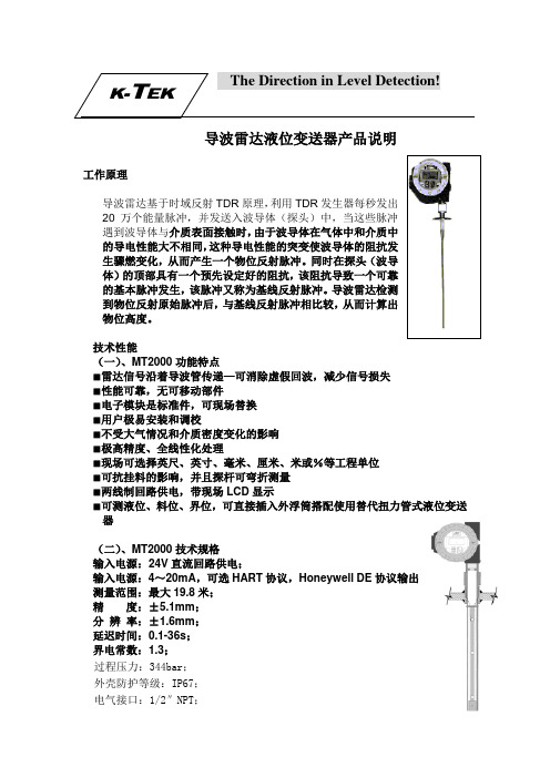
导波雷达液位变送器产品说明工作原理导波雷达基于时域反射TDR 原理,利用TDR 发生器每秒发出20万个能量脉冲,并发送入波导体(探头)中,当这些脉冲遇到波导体与介质表面接触时,由于波导体在气体中和介质中的导电性能大不相同,这种导电性能的突变使波导体的阻抗发生骤燃变化,从而产生一个物位反射脉冲。
同时在探头(波导体)的顶部具有一个预先设定好的阻抗,该阻抗导致一个可靠的基本脉冲发生,该脉冲又称为基线反射脉冲。
导波雷达检测到物位反射原始脉冲后,与基线反射脉冲相比较,从而计算出物位高度。
技术性能(一)、MT2000功能特点■雷达信号沿着导波管传递—可消除虚假回波,减少信号损失 ■性能可靠,无可移动部件■电子模块是标准件,可现场替换■用户极易安装和调校■不受大气情况和介质密度变化的影响■极高精度、全线性化处理■现场可选择英尺、英寸、毫米、厘米、米或%等工程单位 ■可抗挂料的影响,并且探杆可弯折测量■两线制回路供电,带现场LCD 显示■可测液位、料位、界位,可直接插入外浮筒搭配使用替代扭力管式液位变送器(二)、MT2000技术规格输入电源:24V 直流回路供电;输入电源:4~20mA ,可选HART 协议,Honeywell DE 协议输出 测量范围:最大19.8米;精 度:±5.1mm ;分 辨 率:±1.6mm ;延迟时间:0.1-36s ;界电常数:1.3;过程压力:344bar ;外壳防护等级:IP67;电气接口:1/2″NPT ;环境温度:-40~77℃。
过程温度:-185~427℃电磁兼容性:符合CE标准介质粘度:最大1500cp防爆认证:FM:XP/Ⅰ/1/AB/CD/T6,IS/I/1/CD/T4CSA:XP CL I Div 1 GP ABCD;IS CL I Div GP CD T4CENELEC:EEx d IIC T6,EEx ia IIB T6(三)MT2000专用液汽探杆选型代码:/C9/P81探杆材质:316不锈钢高温绝热材质:氧化铝,陶瓷过程连接:3/4″NPTO型密封圈材质:Aegis过程温度:-50℃~335℃过程压力:138bar(四)MT2000应用■介电常数大于1.3的液位测量■电厂各个过程工艺液位测量■当界电常数较大时可实现弯折测量■化工厂易结晶、挂料介质液位测量■侧侧安装取代外浮筒液位变送器应用■超低界电常数粉料测量■界位测量。

带MVD TM技术的1000和2000系列流量变送器2高准1000&2000系列变送器带MVD TM 技术的Micro Motion ® 1000和2000系列变送器传感器电子的新方法只有Micro Motion ®在重定义传感器电子的组合结构中融进了新的MVD TM 技术。
那意味着多变量数字处理可适用于任何流量应用系统中。
MVD 技术把您的大部分基础的或大部分复杂的-应用系统组织起来并且使它们比以前运行更快、更容易及更有效。
MVD 技术MVD 技术使您的Micro Motion 流量计智能化工作。
与模拟设备相比,前端数字处理极大地减少了信号噪音且加快了系统的响应时间。
改进后的MVD 技术还实现了以前绝不可能的多变量测量和自诊断功能。
并且这只是个开始。
只有MVD 技术允许您:.测量多变量.一体式或分体式安装.使用固有的智能诊断很容易地识别和解决问题。
.根据您的应用需要选择变送器的容量。
.在需要时可使变送器的功能升级。
什么是MVD 技术的出发点?通过经改善的过程稳定性和最长的上工时间降低您的基线成本。
可升级的结构您需求什么,Micro Motion 就提供什么,1000和2000系列变送器允许您选择你想要的功能度。
1000系列变送器非常适合应用于要求单变量测量的场合。
对于要求更高的应用场合,2000系列变送器可以同时测量多个变量,并且有更多的输出和数字通讯选项。
当你在1000和2000系列变送器中融进了Micro Motion 的MVD 技术时会发生什么?只有四根配线危险区域认证清洁、无噪声,改善了测量性能的数字信号提供了一套功能组合式的标准性能所有1000系列和2000系列变送器提供:.I级,1分区/1区本地操作器界面:.查看过程变量.快速浏览仪表状态.查看和响应报警.启动、停止、复位变量器总量.流量计调零.执行输出仿真测试.改变测量单位.赋值变量输出.定标输出.设置RS-485通讯选项.界面功能用户化和密码保护.带有360度旋转,紧凑和一体化安装的传感器.经济合理,轻松自如的,4线式分体式安装传感器.实际上无特殊程序要求的简单启动.数字通信.很容易实施自诊断: 仪表状态、被测项目,及更多适合应用于只要求单个流量变量的场合1000系列单变量变送器只适用于要求质量流量或体积流量的测量在任何给定时间内都只需要一个单变量的流量应用中选用1000系列变送器是很理想的。

TRG802XGUIDED WAVE RADAR LEVEL TRANSMITTER TRG802X系列导波雷达物位计使用说明书TRG802X-DT-JS-1005-2018(A)感谢您选择丹东通博电器(集团)有限公司的产品。
本使用说明书给您提供有关安装、连接和调试以及针对维护、故障排除和贮存方面的重要信息。
请在安装调试前仔细阅读并将它作为产品的组成部分保存在仪表的近旁,供随时翻阅。
并可通过输入版本号下载本说明书。
如未遵照本说明书进行操作,则本仪表所提供的防护可能会被破坏。
商标、版权和限制说明通博、通博电器、通博泵业、DDTOP、均为公司的注册商标。
本仪表的性能规格自发布之日起生效,如有更改,恕不另行通知。
丹东通博电器(集团)有限公司有权在任何时候对本说明书所述的产品进行修改,恕不另行通知。
质保丹东通博电器(集团)有限公司保证所有刮板流量计自出厂之日起,一年之内无材料和制造工艺方面的缺陷。
在质保期内,如产品出现质量问题而返回,提出的索赔要求经制造厂检验后确定属于质保范围内,则丹东通博电器(集团)有限公司负责免费为买方(或业主)维修或更换。
丹东通博电器(集团)有限公司对因设备使用不当,劳动力索赔、直接或后续损伤以及安装和使用设备所引起的费用概不负责。
除了关于丹东通博电器(集团)有限公司某些产品的特殊书面保修证明,丹东通博电器(集团)有限公司不提供任何明示或暗示的质量保证。
质量丹东通博电器(集团)有限公司通过了ISO9001质量体系认证,产品生产的全过程均严格依照质量体系的规定范围执行,对产品和服务质量提供最强有力的保证。
1安全提示 (4)1.1爆炸可能会导致死亡或严重伤害。
(4)1.2过程泄漏可能导致严重伤害或死亡。
(4)1.3不遵守安全安装准则可能导致死亡或严重受伤。
(4)2产品说明 (4)2.1 主要结构 (4)2.2 工作原理 (5)2.3包装 (5)2.4吊装运输时 (5)2.5仓储 (5)3技术特性 (5)3.1主要技术参数 (5)3.2 外观及性能参数 (5)3.3 防爆标志 (7)3.4执行标准 (7)4 外形尺寸示意图 (8)5开箱及检查 (11)5.1开箱验货注意事项 (11)5.2检查内容 (11)6安装 (11)6.1安装工具 (11)6.2安装要求 (11)7 仪表调试 (13)7.1 电气接线 (13)7.2调试操作过程 (13)8注意事项 (21)9故障分析与排除 (21)10拆卸 (22)10.1警告 (22)10.2 废物清除 (22)11 产品认证 (22)1安全提示出于安全的原因,明确禁止擅自改装或改变产品,维修或替换只允许使用由制造商指定的配件。
MT2000导波雷达液位变送器安装调试操作手册1) 存储须知:如有必要需在安装前予以保存,请将其保存在室内常温的条件下,不要超过以下范围:温度范围:-40℃~65.5℃湿度:0 ~100%R.H. 无冷凝2) 产品简介及工作原理:MT2000是4~20mA回路供电采用微处理器的智能物位变送器,可提供HART或Honeywell DE数字信号输出。
它使用非常低的微波能量来探测被测物体的物位。
为了获得最好的性能,了解其工作原理是很重要的。
电子变送器外壳安装在一个特殊的连接器上配合过程连接,并且密封,同时带一个硬杆或电缆。
这个形如探杆的硬杆或电缆悬挂在容器中,起一个导波的作用,也就是说微波能量集中在探杆中,并沿着探杆传递,从而替代没有探杆的锥形散射。
一个测量周期由以下几步组成:1、电子变送器产生一个非常短的微波能量脉冲,沿着探杆传递。
2、脉冲沿着探杆传递,直到它遇到一个不连续的,突然的介电常数的变化,像物位面,能量被反射回来并沿着导波管传递到电子变送器。
3、当反射脉冲到达电子变送器时,被其检测到。
通过测量消逝的时间从起始脉冲到反馈脉冲,电子变送器可以计算出待测的物位。
4、由于微波以光速传递,一个完整的测量周期是由几千个脉冲组成。
电子部件使用采样技术来重建复制一个实际时间信号波形,但以低得多的速度,以便微处理器能够处理。
这个过程类似如频闪观测仪的效果,当用频闪灯光来观察高速运转的机器时候。
5、测量周期是每秒10次,同时,在产生当前的输出信号(正比于待测的物位)以前,使用独特的滤波技术进行处理,保证信号的精度。
探测信号过程如下:1、起始脉冲2、不连续反射3、从物位返回来的信号4、从探杆末端返回来的信号测量原理本质上基于这样一个事实:介电常数的突变将产生一个在基线下有一定振幅的负脉冲。
介电常数变化越大,反馈回来的信号的幅度也越大。
这意味着如果存在一个实质性的变化,如从管嘴的直径到一个敞开的容器,例如下图所示过程连接的曲线图。
Features− SIL 2/3 Certified IEC 61508*− Graphic Display with Waveform Screen − Widest Selection of Wetted Materials − Radar Signal Travels Along the Waveguide –Eliminates False Echoes and Minimizes Signal Loss − No Moving Parts− Rigid, Flexible Cable & Coaxial Probes − All Digital Electronics− Loop Powered to 217ft Probe Length − Total and/or Interface Level Measurement−Field Replaceable / Upgradable Electronics ModuleMT5000 SeriesGuided wave radar level transmitterOptions− FOUNDATION fieldbus output − Glass viewing window − 316 Stainless Steel enclosure −Remote sensor* transmitters equipped with 4-20mA/HART module option onlyAccessories− External chambers − Stilling wells− JDF200 loop indicator−RI100 Repeat Indicator for 2 4-20mA Output SignalsHigh accuracylevel and interface detection for liquids, slurries and solids K -TEK Products1 see approval agency restrictionsSpecifications SensorMT5100 INTERFACE GUIDELINESIn order to properly detect the level of interface between two liquids using the MT5100, the following rules must be adhered to:1.One of the following probe and mounting configurations must be used:a.Single rigid rod or flexible cable mounted in a stilling well, external chamber, or existing displacer.*b.Coaxial probe mounted into tank, external chamber, or displacerc.Single rigid rod or flexible cable in open vessel with recommended installation conditions.*This is the preferred mounting configuration to reduce the chance of fouling.2.Emulsion layers will affect the detection of an interface level. An emulsion layer may negate an interfacelevel indication completely. The MT5100 will read an interface level in the presence of a 3 inch emulsion.Greater emulsion layers may be possible. Please consult factory.3.The minimum upper fluid thickness must be 4 inches when emulsion is present, and 3 inches with a cleaninterface. Closer measurement may be possible with calibration adjustment.4.The upper fluid dielectric constant must be greater than 1.4 and less than5.5.The interface level indication is a calculated value based partially upon the dielectric of the upper fluid. Theupper fluid dielectric must remain constant for consistency / accuracy in the interface level indication.6.The lower fluid dielectric constant must not be less than 15.7.If the application is a flooded condition (sensor completely submerged in process), it must remaincompletely flooded.8.In a non-flooded condition, the upper fluid must not be allowed to enter the upper unmeasurable zone. Theupper unmeasurable zone is typically located within the mounting nozzle of the vessel.9.If measuring interface in an external chamber, ensure that the fluid is allowed to equalize between thevessel and the chamber. Consult the factory or your local representative for assistance.10.R and RW remote coupler configurations are not recommended for interface applications unless the remotecoax is 5ft or less and the probe is a coaxial configuration or in a chamber or stilling well.If the required interface application does not fall within the above mentioned parameters, please consult the factory for an alternate technology, such as an LMT Series magnetostrictive transmitter or a KM26 magnetic level gauge.GUIDELINES FOR MEASURING with ULD MODEPROCESS CONNECTION / WAVEGUIDE COUPLERO -Ring Seals*Order CodeDescription Min. Temp Max. Temp VViton A (FKM) -15ºF -26ºC 400ºF 204ºC K Kalrez 4079 -40ºF -40ºC 400ºF 204ºC E EPDM -60ºF -50ºC 250ºF 125ºC AMarkez Z1319-14ºF -10ºC572ºF 300ºCPressure versus Temperature for C1 and C2 CouplersPressure versus Temperature for C1H and C2H CouplersPressure versus Temperature for C8 CouplersPressure versus Temperature for C9 Couplers 2Pressure / Temperature Curves 1*The information in this chart has been supplied by the o -ring manufacturers. Before permanent installation, test theequipment with the chemicals and under the specific conditions of your application.If the required o -ring material is not listed above, please consult the factory.1. Coupler temperatures are based on o -ring temperature ratings. Please refer to the o -ring chart above for further information.2. C9 coupler temperature rating is based on Markez Z1319 o -ring selection. The temperature is based on o -ring placement in side the coupler, thus allowing higher temperatures at the process connection.Cable weights for cable probesCentering disks for rod probes444L1L2Active Length6” minimum diameter surface90°L1L26” minimum diameter surface3”H Max Coupling 3Active Length90°HSL1L2Active Length6” minimum diameter surface for nozzles 3”or smaller90°41.71.7L2Act. LengthL1CENTERINGDISKL1L2Act. LengthCENTERINGDISK2” typical 90°HSL1L2ACTIVE LENGTH5” diameter minimum 90°L1L2Active LengthProbeIntegral Stilling Well1.711MT5100 Recommended Installation Pipe; Customer or K -TEK Supplied.ILL1L2ILL2L1ILL1L2Pipe; Customer or K -TEK Supplied. Refer-1) to specify /order external chamber available online at on the Displacer End of probe or top of weight should extend a minimum of (50mm) below lower process connection of chamber.ILL1L2 Open Vesselminimum diameter surfaceBase Model for MT5000, MT5100 and MT5200 TransmittersMT5000 Series Guide Wave Radar MT5.xxx xxxx xx x xx(x) Device TypeMT5000, Liquid Total Level Transmitter000MT5100, Total Level and Interface Level Transmitter100MT5200, Solids and Low Dielectric Liquid Total Level Transmitter200Coupler MaterialNone Y316/L Stainless Steel (Standard)S6*304/L Stainless Steel (Rigid Probe only)S4Hastelloy C-276H1Hastelloy B3 (Rigid Probes only)H3Monel M4Titanium (Rigid Probes only)T2Inconel 625IN2Special Z9Transmitter ConfigurationNone YLocal Transmitter (Standard)L*Local Transmitter with Window Cover (Standard)LW*Remote Mounted Electronics with Standard 5 ft Cable (Dielectric > 15)RRemote Mounted Electronics with Window Cover and Standard 5 ft Cable (Dielectric > 15)RWSpecial Z9 Transmitter HousingNone YDual Compartment Aluminum Housing (Standard)A* Dual Compartment 316 Stainless Steel Housing S Special Z Process Connection / Waveguide CouplerNone Y 0.75 in. NPT Process Connection Coupler Single / Coaxial Probe Teflon Insulator C1*0.75 in. NPT Process Connection Coupler Single / Coaxial Probe Teflon Insulator High Pressure C1H1.50 in. NPT Process Connection Coupler Single / Coaxial Probe Teflon Insulator C2*1.50 in. NPT Process Connection Coupler Single / Coaxial Probe Teflon Insulator High Pressure C2H2.50 in. NPT Process Connection Coupler Single / Coaxial Probe Teflon Insulator C3 1.50 in. NPT Process Connection HP/HT Coupler Single Probe/Coaxial Probe Borosilicate Glass Insulator C8 1.0 in. NPT Process Connection HP/HT Coupler Single Probe/Coaxial Probe Alumina Ceramic InsulatorC9 Custom Coupler, consult factory CZ * -Standard12Base ModelMT5000 Series Guide Wave Radar ordering information continuedMT5.xxx.xxxx.xx.x.xxx.x(xxx)xxx(xxxxxx) Process Seal TypeNone YV*Viton FKM A O-Ring Process Seal -15 °F (-26 °C) Min Temp to 400 °F (204 °C) Max Temp StandardAdditional Hermetic Glass Feed-Through with Viton FKM A O-Ring Process Seal SV1*Kalrez 4079 O-Ring Process Seal -40 °F (-40 °C) Min Temp to 400 °F (204 °C) Max Temp K*Additional Hermetic Glass Feed-Through with Kalrez 4079 O-Ring Process Seal SK1*EPDM O-Ring Process Seal -60 °F (-50 °C) Min Temp to 250 °F (125 °C) Max Temp EAdditional Hermetic Glass Feed-Through with EPDM O-Ring Process Seal SE1*Markez Z1319 O-Ring Process Seal -14 °F (-10 °C) Min Temp to 572 °F (300 °C) Max Temp A*Additional Hermetic Glass Feed-Through with Markez Z1319 O-Ring Process Seal SA1* Borosilicate process seal, C8 coupler only B*Additional Hermetic Glass Feed-Through with Borosilicate Process Seal, C8 coupler only SB1*Special Process Seal Z9Probe TypeNone YRod probesSingle Rigid Rod Probe, 0.25 in. (6 mm) Outer Diameter, 20 ft (6.1 m) Max Standard Length P01* Single Rigid Rod Probe, 0.50 in. (13 mm) Outer Diameter, 20 ft (6.10 m) Max Standard Length P02* Single Rigid Rod Probe 0.375 in. (9 mm) Outer Diameter, 20 ft (6.1 m) Max Standard Length P03*Simi-Rigid Rod Probe 0.125 in. (3 mm) Outer Diameter 50 ft (15.24 m) Max Standard Length Includes Weight P43 Cable probesSingle Flexible Cable Probe 0.1875 in. (5 mm) Outer Diameter, 200 ft (61 m) Max Standard Length P11* Single Flexible Cable Probe 0.25 in. (6 mm) Outer Diameter, 200 ft (61 m) Max Standard Length P12* Triangle Cable Probe 0.25 in. (6 mm) Outer Diameter, 100 ft (30.5 m) Max Standard Length P33 Single Flexible Cable Probe 0.31 in (8 mm) Outer Diameter, 200 ft (61 m) Max Standard Length P61 Coaxial probesCoaxial Probe 0.875 in. (22 mm) Outer Diameter 22 ft (6.7.5 m) Max Standard Length P51 Coaxial Probe 1.315 in. (34 mm) Outer Diameter 316SS only 22 ft (6.7.5 m) Max Standard Length P71 Coaxial Probe 0.1875 in. (5 mm) Outer Diameter 316SS only 22 ft (6.7.5 m) Max Standard Length P81 Coaxial Probe 1.00 in. (25 mm) Outer Diameter 22 ft (6.7.5m) Max Standard Length with compression fitting P912 Custom Probe, consult factory PZZ1. Hermetic seal required for E1 and E2 approvals2. Maximum process pressure of3.45 barg (50 psig)* - Standard13Base ModelMT5000 Series Guide Wave Radar ordering information continuedMT5.xxx.xxxx.xx.x.xx(x).x(xxx).xxxx xxxx xx Probe end attachmentNone YCentering weights (cable probes only)0.875 in. (22.2 mm) O.D., 4.0 in. (101.6 mm) Weight Height, approx. 0.7 lbs (301 g)W09*1.0 in. (25.4mm) O.D., 6.0 in. (152.4 mm) Weight Height, approx. 1.3 lbs (590 g)W10*1.25 in. (31.75 mm) O.D., 3.5 in. (88.9 mm) Weight Height, approx. 0.8 lbs (317 g)W13*1.625 in. (41.3mm) O.D.,2.0 in. (50.8 mm) Weight Height, approx. 1.1 lbs (499 g)W161.875 in. (47.6 mm) O.D.,2.0 in. (50.8 mm) Weight Height, approx. 1.5 lbs (680 g)W192.875 in. (73.3 mm) O.D., 1.0 in. (25.4 mm) Weight Height, approx. 1.8 lbs (816 g)W292.00 in. (50.8 mm) O.D., 6.0 in. (152.4 mm) Weight Height, approx. 2.2 lbs (998 g)WS61.5 in. (38.1 mm) O.D., 5.25 in. (133.35 mm) Weight Height, approx.2.2 lbs (998 g)W61Custom Centering Weight (consult factory)W99 Centering disks (rod probes only)1.50 in. (38.1 mm) O.D. approx 0.4375 in. (11 mm) Height 1.50 in. (38.1 mm) Min Stilling Well Size D152.0 in. (50.8 mm) O.D. approx 0.4375 in. (11 mm) Height 2.0 in. (50.8 mm) Min Stilling Well Size D202.3 in. (58.7 mm) O.D. approx 0.4375 in. (11 mm) Height 2.5 in. (63.5 mm) Min Stilling Well Size D232.8 in. (71.1 mm) O.D. approx 0.4375 in. (11 mm) Height3.0 in. (76.2 mm) Min Stilling Well Size D283.75 in. (95.3 mm) O.D. approx 0.4375 in. (11 mm) Height4.0 in. (101.6 mm) Min Stilling Well Size D383.75 in. (95.3 mm) O.D. approx 0.4375 in. (11 mm) Height4.0 in. (101.6 mm) Min Stilling Well Size D60Custom Centering Disk (consult factory)D99Eyelets (cable probes only)Eyelet SS6 for 0.1875 in. (5 mm) O.D. Cable E1Eyelet SS6 for 0.25 in. (6 mm) O.D. Cable E2Special Z9Probe Attachment MaterialNone Y316/L Stainless Steel, Standard S6* 304/L Stainless Steel S4 Hastelloy C-276H1 Monel M4 Inconel 600N2 Special Z9 Process Temperature ExtensionProcess Temperature 32 °F (0 °C) to 250 °F (121 °C) Standard H0 Temperature Extension, extends electronics additional 6 in. above process connection H6 Special Z914Base ModelMT5000 Series Guide Wave Radar ordering information continuedMT5.xxx.xxxx.xx.x.xx(x).x(xxx).xxxx.xxxx.xx.xxxx.x(xxxx)xxx xxxx xxx Electronics ModuleNone YTotal Level, Graphic Display, 4 ... 20 mA Output, HART M7ATotal Level, Graphic Display, FOUNDATION fieldbus M7AFTotal and/or Interface Level, Graphic Display, 4 ... 20 mA Output, HART M7BTotal and/or Interface Level, Graphic Display, FOUNDATION fieldbus M7BFSpecial Z9Agency ApprovalsGeneral purpose Y0IECEx Intrinsically safe E1IECEx Flameproof E2FM / CSA Intrinsically safe N1FM / CSA Explosion proof Housing N2Special Z9Process Connection TypeNone Y0 Integral Thread, Standard Process Connection P4* Welded Process Connection P2 Loose flange for use with NPT threads. Specify flange type, material, and rating P3 Special Z9 Process Connection MaterialNone Y 304/L Stainless Steel S4 316/L Stainless Steel S6* Carbon Steel C1 Hastelloy C-276H1 Alloy 20A2 Monel 400M4 Super Duplex Stainless Steel D2 Special Z915Base ModelMT5000 Series Guide Wave Radar ordering information continuedMT5.xxx.xxxx.xx.x.xx(x).x(xxx).xxxx.xxxx.xx.xxxx.xxxx Flange or Plug Size // Rating / TypeNone Y3/4" MNPT Threaded (C1, C1H process couplers)NTBN* 1.0" MNPT Threaded (C9 process coupler)NTCN*1.5" MNPT Threaded (C2, C2H and C8 process couplers)NTEN*2.5" MNPT Threaded (C3 process coupler)NTGN 3/4" G thread, British Pipe Thread (BSPP), (C1, C1H process couplers)GTBN 1.0" G thread, British Pipe Thread (BSPP), (C9 process coupler)GTCN1.5" G thread, British Pipe Thread (BSPP), (C2, C2H and C8 process couplers)GTEN2.5" G thread, British Pipe Thread (BSPP), (C3 process coupler)GTGN 1 in. // ANSI / ASME Class 150 // Raised Face Flange R111 in. // ANSI / ASME Class 300 // Raised Face Flange R131 in. // ANSI / ASME Class 600 // Raised Face Flange R16 1.5 in. // ANSI / ASME Class 150 // Raised Face Flange R151 1.5 in. // ANSI / ASME Class 300 // Raised Face Flange R1531.5 in. // ANSI / ASME Class 600 // Raised Face Flange R1562 in. // ANSI / ASME Class 150 // Raised Face Flange R212 in. // ANSI / ASME Class 300 // Raised Face Flange R232 in. // ANSI / ASME Class 600 // Raised Face Flange R26 2.5 in. // ANSI / ASME Class 150 // Raised Face Flange R251 2.5 in. // ANSI / ASME Class 300 // Raised Face Flange R2532.5 in. // ANSI / ASME Class 600 // Raised Face Flange R2563 in. // ANSI / ASME Class 150 // Raised Face Flange R313 in. // ANSI / ASME Class 300 // Raised Face Flange R333 in. // ANSI / ASME Class 600 // Raised Face Flange R364 in. // ANSI / ASME Class 150 // Raised Face Flange R414 in. // ANSI / ASME Class 300 // Raised Face Flange R434 in. // ANSI / ASME Class 600 // Raised Face Flange R466 in. // ANSI / ASME Class 150 // Raised Face Flange R616 in. // ANSI / ASME Class 300 // Raised Face Flange R636 in. // ANSI / ASME Class 600 // Raised Face Flange R66 DN 25 // PN 25 // Raised Face Flange D2525 DN 25 // PN 40 // Raised Face Flange D2540 DN 32 // PN 25 // Raised Face Flange D3225Note: DIN flanges are per EN1092-116Base ModelMT5000 Series Guide Wave Radar ordering information continuedMT5.xxx.xxxx.xx.x.xx(x).x(xxx).xxxx.xxxx.xx.xxxx.xxxx Flange or Plug Size // Rating / Type - Continued from previous pageDN 32 // PN 40 // Raised Face Flange D3240 DN 40 // PN 25 // Raised Face Flange D4025 DN 40 // PN 40 // Raised Face Flange D4040 DN 50 // PN 25 // Raised Face Flange D5025 DN 50 // PN 40 // Raised Face Flange D5040 DN 65 // PN 25 // Raised Face Flange D6525 DN 65 // PN 40 // Raised Face Flange D6540 DN 80 // PN 25 // Raised Face Flange D8025 DN 80 // PN 40 // Raised Face Flange D8040 DN 100 // PN 25 // Raised Face Flange D10025 DN 100 // PN 40 // Raised Face Flange D10040 DN 125 // PN 25 // Raised Face Flange D12525 DN 125 // PN 40 // Raised Face Flange D12540 DN 150 // PN 25 // Raised Face Flange D15025 DN 150 // PN 40 // Raised Face Flange D15040 1.0 in. // ANSI / ASME Class 3000 // NPT-m Hex Plug P11.5 in. // ANSI / ASME Class 3000 // NPT-m Hex Plug P152.0 in. // ANSI / ASME Class 3000 // NPT-m Hex Plug P22.5 in. // ANSI / ASME Class 3000 // NPT-m Hex Plug P253.0 in. // ANSI / ASME Class 3000 // NPT-m Hex Plug P3Any flange not listed above, consult factory Z9 Note: DIN flanges are per EN1092-1Option codes are on the following page.Option codes follow the model code with a dash (-)17MT5000 Series guided wave radar transmitter additional option codesAdditional options MT5.xxx.xx(x).x(xx)x.xx.xxx(xx).x(x).xx(x)- xxx xxx xxx xxxx xx Additional Approvals or CertificationsFurnished with CRN data package (includes tagging, MTR and hydro tests)CRNNuclear use, device to be used in a nuclear facility (application must be reviewed by ABB)P4Special CLZSensor optionsElectro-polish finish on wetted metal surfaces (not possible with cable or coax probe designs)SEL240 grit polish on wetted metal surfaces (not possible with cable or coax probe designs) SEPAdd Teflon sleeve on probe for slip resistance only, not for corrosion resistance SENAdd 1/4" purge or flush port (requires extended process coupler)SEBExtended process coupler, specify distance SE1Segment probe into 10ft sections, specific rod and coax probe selections SE3 Degreased (oil and grease free) for oxygen or chlorine service P1Sensor special SEZTarget float optionsAdd 316L target float, minimum fluid specific gravity 0.6FT1 Special target float per application requirements FZ9 Remote electronics signal cable length (For remote coupler only)1.5 m (approx. 5 ft)SRW3 m (approx. 9.8 ft)SRT5 m (approx. 16.4 ft)SR1 Custom coaxial remote length SRZ Repeat Indicator (for two analog level outputs)RI100 remote indicator (HART only), requires additional 4-20 loop, same material as transmitterhousing AR Option codes continue on the following page.Option codes follow the model code with a dash (-)18MT5000 Series guided wave radar transmitter additional option codesAdditional options MT5.xxx.xx(x).x(xx)x.xx.xxx(xx).x(x).xx(x)-xxx.xxx.xxx.xxxx.xx.xxx xx xxxx xx xxx xx xxxAdd rod extension rod to probe (material and diameter determined by couplerselection)152.4 mm (6.0 in)AR1304.8 mm (12.0 in.)AR2457.2 mm (18 in.)AR3Special AR9Mounted AccessoriesCentering spacers as specified separately on order ASCentering disk for cable weight (cable probes only, disk material same as weight)1.50 in. (38.1 mm) O.D.; 1.50 in. (38.1 mm) Min Stilling Well Size WD12.0 in. (50.8 mm) O.D.; 2.0 in. (50.8 mm) Min Stilling Well Size WD22.3 in. (58.7 mm) O.D.; 2.5 in. (63.5 mm) Min Stilling Well Size WD32.8 in. (71.1 mm) O.D.;3.0 in. (76.2 mm) Min Stilling Well Size WD43.75 in. (95.3 mm) O.D.;4.0 in. (101.6 mm) Min Stilling Well Size WD54.0 in. (101.6 mm) O.D.;5.0 in. (125 mm) Min Stilling Well Size WD6Custom disk for cable weight (consult factory)WDZDevice Identification PlateAdd stainless steel hang tag with custom tag no.T1Add stainless steel hang tag, custom markings 4 lines, 22 characters per line TSOther tagging special TZElectrical Connector TypeFieldbus 7/8 in. (without mating plug)U1Fieldbus M12 x 1 (without mating plug)U2M20 stainless steel adapter U8M20 brass adaptor U9Electrical Connector Special UZSurge ProtectorSurge / Transient protector S1Special OtherTransmitter Special Option STTTower length extension special length - meter insulation capability TEZ Special paint or treatment on housing STH Special paint or treatment on flange STF Additional requirements and order comments are continued on the following page.All codes located behind the // are for additional requirements and order comments.These codes will not be included on the device tag.19All codes located behind the // are for additional requirements and order comments.These codes will not be included on the device tag.MT5000 Series guided wave radar additional option codesAdditional requirements and order comments MT5..............x- …//xx xxx CertificatesTest report 2.2 acc. EN 10204C1MTR 3.1, Material monitoring with inspection certificate 3.1 acc. EN 10204C2MTR 3.2, Material monitoring with inspection certificate 3.2 acc. EN 10204C3Declaration of compliance with the order 2.1 acc. EN 10204C4Material monitoring NACE MR 0175, MR 0103 with inspection certificate 3.1 acc. EN 10204CNPrinted record of configured settings in transmitter CGWith hydrostatic test report CHWith PMI report on wetted metal materials CJOther certificates CZDrawingsDrawings for approval required prior to construction GD1Drawings for record required GD2Certified as built drawings required GD3Other drawings GDZAdditional requirements and order comments are continued on the following page.All codes located behind the // are for additional requirements and order comments.These codes will not be included on the device tag.20MT5000 Series guided wave radar additional option codesAdditional Requirements and coder comments MT5.............x-…//xx.xx.xx.xxx.xx xx xx xx Documentation Language (installation, operation and maintenance manual)German M1Italian M2Spanish M3French M4English M5Russian MBOthers MZ Calibration Type3-point calibration verification certificate, factory default 90, 50 and 10% of measurable zone,or customer specified points within measurable zone R35-point calibration verification certificate, factory default 90, 75, 50, 25 and 10% of measurable zone,or customer specified points within measurable zone R5 Custom Linearization or Strapping table entered (up to 20 pts). RL Witnessed calibration with certificate RW Special calibration RZ Programming and Parameter SettingsCustom parameter settings N6 Software SpecialSpecified software version V1 Custom software version VZProbe LengthMinimum 24 in. in. Minimum 609.6 mm mm21Contact usABB Inc.Measurement & Analytics3400. Rue Pierre-ArdouinQuébec, Québec G1P 0B2 CANADA Office Phone: +1 418.877.2944 ext. 2109 Direct Line : +1 581.628.2109E-mail:*************.com/levelABBMeasurement & AnalyticsNo. 5, Lane 369, Chuangye Road, Kangqiao Town, Pudong District Shanghai, 201319, P.R.ChinaTel:+86 10 64231407Fax:+86 10 64371913/level NoteWe reserve the right to make technical changes or modify the contents of this document without prior notice. With regard to purchase orders, the agreed particulars shall prevail. ABB does not accept any responsibility whatsoever for potential errors or possible lack of information in this document.We reserve all rights in this document and in the subject matter and illustrations contained therein. Any reproduction, disclosure to third parties or utilization of its contents - in whole or in parts –is forbidden without prior written consent of ABB.Copyright © 2020 ABBAll rights reservedDS/MT5-ENRev.C11.2222。
【雷达物位计】雷达物位计四个常见问题1.雷达物位计订货选型需要了解的数据_仪表网雷达波是一种特别形式的电磁波,雷达物位计利用了电磁波的特别性能来进行料位检测。
电磁波的物理特性与可见光相像,传播速度相当于光速。
其频率为300MHz—3000GHz。
电磁波可以穿透空间蒸汽、粉尘等干扰源,碰到障碍物易于被反射,被测介质导电性越好或介电常数越大,回波信号的反射效果越好。
用于液体或固体的非接触液位变送器不受电导常数,温度,压力和密度变化影响,雷达物位计的精度可达1mm 测量范围可达100m ,罐底跟踪(TBF)方式用于测量低电导常数,介质法兰温度可达250C 介质温度—60C600C 压力可达64bar,雷达物位计适用于酸碱储罐、浆料储罐、固体颗粒、小型储油罐。
各类导电、非导电介质、腐蚀性介质。
如煤仓、灰仓、油罐、酸罐等。
一、雷达物位计使用注意事项:1、本仪表在室外使用,安装遮阳篷或者保护箱,以免时间长了,液晶屏受阳光照射而老化。
假如在有腐蚀性气体的环境中使用,需要加装防腐外套,并且拧紧仪表的外表壳和进出线端子。
雷达物位计在有腐蚀性气体或液体的场合使用,或者在海边、海上使用,需要选用防腐型的。
2、电线、电缆保护管,要注意密封防止积水,防止被老鼠等啮齿类动物撕咬。
3、仪表虽然自身带有防雷器件,但雷达物位计在多雷地区使用时,建议在仪表的进出线端另外安装专用的防雷装置。
4、仪表在特别酷热、寒冷的地方使用,即四周环境温度有可能超出仪表的工作要求时,建议在液位仪四周加设防高、低温装置。
5、雷达要和被测的液面垂直,在雷达的电磁波发射的锥形的范围内不能有其它障碍物。
6、假如在—20℃或+60℃的温度下使用,请事先本公司的技术服务部门。
7、雷达物位计使用环境有粉尘、蒸汽、雾气,液面有泡沫、漂流物,液体有搅拌,波浪等情况请事先本公司技术服务部门,需要区分对待。
二、雷达物位计订货选型需要知道的数据:1、被测量的介质类型,液体还是固体。
MT2000导波雷达物位变送器
概述
MT2000导波雷达液位变送器采用先进的导波雷达(GWR)技术,雷达信号沿着导波杆或者导波缆传输,可消除虚假回波,减少信号损失,仪表具有不受大气情况和介质密度变化的影响,测量精度高,测量范围大,且有多种过程连接方式,安装使用方便等特点。
仪表输出4~20mA标准电流信号,可选HART协议或HoneywellDE协议进行通讯。
工作原理
K-TEK导波雷达物位变送器采用TDR时域反射原理,电子变送器外壳下有一个特殊的压电晶体,它与过程连接相连,变送器通电后,压电晶体会产生一个沿导波杆(硬杆或软缆探头)向下传送的电磁脉冲波,当电磁脉冲波遇到比先前传导介质(如空气)介电常数大的介质表面时将会沿着导波杆反射回去并被压电晶体接收到,变送器可以计算出电磁脉冲波从发射到接收的时间间隔,从而可精确地测量出物位高度。
产品特点
◆雷达信号沿着导波管传输,可消除虚假回波,减少信号损失
◆无活动部件
◆优异的抗挂料能力
◆不受大气情况和介质密度变化的影响
主要技术参数
测量范围:0.6~30.5m
精确度:±5mm
分辨率:±1.6mm
工作电源:13.5~36VDC,二线制
输出信号:4~20mA,HART
电气接口:1/2"NPT内螺纹
介质介电常数:≥1.3
介质最大粘度:1500cp
工作温度:-185~350℃
环境温度:-40~80℃
工作压力:-0.1~13.8MPa
探杆材质:316L、哈氏C、钛材、PTFE等
过程连接:螺纹:3/4~2.5"NPT法兰:HG20592~20635-97 DN50以上法兰,其他法兰标准(如GB、JB/T、HGJ、ANSI、DIN等)请用户在订货时注明
壳体材质:铝合金;不锈钢
防护等级:IP67
认证:FM、CSA、CENELEC
隔爆型:Ex dIICT6
本安型:Ex iaIIBT6
选型表。