B0安装及使用教程
- 格式:ppt
- 大小:38.67 MB
- 文档页数:29

Backup Box-(B0, B1) Quick GuideIssue: 04Date: 2023-02-1511.The information in this document is subject to change without notice. Every effort has been made in the preparation of this document to ensure accuracy of the contents, but all statements, information, and recommendations in this document do not constitute a warranty of any kind, express or implied.2.Before installing the device, read the user manual carefully to get familiar with product information and safety precautions.3.Only certified electricians are allowed to operate the device. Operation personnel must wear proper personal protective equipment (PPE).4.Before installing the device, check that the package contents are intact and complete against the packing list. If any item is missing or damaged, contact your dealer.5.The device damage caused by the violation of instructions in this document is not covered under warranty.6.The cable colors involved in this document are for reference only. Select cables in accordance with local cable specifications.FunctionThe Backup Box is used in a residential rooftop PV plant system to control the inverter grid-tied or off-grid state. When the grid fails, the inverter switches to the off-grid state and supplies power to off-grid loads in backup mode. When the grid recovers, the inverter switches back to the grid-tied state.Model NumberNo.Meaning Value1Product name Backup Box: Backup Box 2Design codeB0: single-phase B1: three-phaseSystem NetworkingThe grid-tied system of a rooftop PV plant consists of PV strings, an energy storage system (ESS),an inverter, a Backup Box, a management system, an AC switch, and a power distribution unit.Supported Grid TypesThe Backup Box supports the following grid types: TN-S, TN-C-S and TT. When the inverter is inthree-phase, three-wire mode, the Backup Box does not support off-grid operation.•Off-grid electric motor loads are not supported. The startup power of an electric motor is several times of its rated power, which may exceed the load capacity of the Backup Box, resulting in startup failure.•The off-grid load port cannot be directly connected to the power grid. Otherwise, the off-grid function is unavailable, causing shutdown upon overload.•The power of off-grid loads cannot exceed the maximum off-grid output power of the inverter.Appearance(1) Front panel(2) Lock(3) Hanging kit(4) Off-grid load port (BACKUP LOAD)(5) Grid AC port (GRID)(6) Inverter AC port (INVERTER AC)(7) COM port (COM)(8) Ventilation valve(9) Ground point(10) Off-grid load switch3Installation Space Angle1.When a Backup Box is installed outdoors, avoid direct sunlight. You are advised to install it in a sheltered place or install an awning over it.2. A surge protective device (SPD) needs to be installed on the grid side of the Backup Box.Installation Requirements2.12Mounting Holes and DimensionsWhen drilling holes, avoid the water pipes and power cables buried in the wall.Installing a Backup Box2.2⚫M6x60 expansion bolts are delivered with the Backup Box. If the length and number of the bolts do not meet installation requirements, prepare M6 stainless steel expansion bolts by yourself.⚫The expansion bolts delivered with the inverter are mainly used for solid concrete walls. For other types of walls, prepare bolts by yourself and ensure that the wall meets the load bearing requirements of the inverter.⚫In residential areas, do not install the inverter on drywalls or walls made of similar materials which have a weak sound insulation performance because the noise generated by theinverter is noticeable.LevelPreparations3.1⚫Connect cables in accordance with local installation laws and regulations.⚫Before connecting cables, ensure that the circuit breaker on the Backup Box and all the switches connecting to the Backup Box are set to OFF position. Otherwise, the high voltage of the Backup Box may result in electric shocks.⚫After opening the device panel of the Backup Box, remove the shockproof foam. Otherwise, the circuit breaker cannot work properly.⚫If the external AC switch can perform earth leakage protection, the rated leakage action current should be greater than or equal to 100 mA.⚫If multiple SUN2000s connect to the general residual current device (RCD) through their respective external AC switches, the rated leakage action current of the general RCD should be greater than or equal to the number of SUN2000s multiplied by 100 mA.⚫The rated input voltage of the Backup Box is 220 V/230 V (single-phase) or 380 V/400 V (three-phase). If the device runs in a weak power grid area, a self-recoveryovervoltage/undervoltage protector needs to be installed at the upstream of the X2 AC power grid input terminal of the Backup Box. This ensures that the device can bedisconnected from the power grid when the power grid voltage is abnormal, preventing damage.3No.Cable Type Conductor Cross-Sectional Area RangeOuter Diameter1PE cable Single-core outdoorcopper cable4–10 mm2N/A2Off-grid loadoutput power cableOutdoor copper cable4–6 mm210–21 mm3Grid AC outputpower cableOutdoor copper cable4–6 mm210–21 mm4Inverter AC inputpower cableOutdoor copper cable4–6 mm210–21 mm5Signal cable Two-core outdoorshielded twisted paircable0.20–1 mm24–8 mmPrepare cables based on site requirements.Installing an Output Power Cable for Off-Grid Loads3.3X1Before installing a cable, open the panel of the Backup Box, route the cable through the off-gridload port, and connect the cable. After all cables are connected, reinstall the panel.Off-Grid Load Terminal (X1)No..1234Single-PhaseLN-PEOff-Grid Load Terminal (X1)No..1234Three-Phase LN-PEStrip the cable to the wiring portInstalling a PE Cable3.2Do not connect the neutral wire to the enclosure as a PE cable. Otherwise, electric shocks mayoccur.Ground pointIf multiple inverters are connected in parallel, the connection of AC power cables L1, L2, and L3 on the power grid side of the Backup Boxes connected to each inverter must be the same.Installing an Inverter AC Input Power Cable3.5X2Connecting AC Input Terminals of the Inverter (X3)No.1234567891011Single-Phase-L---N---PE-Connecting AC Input Terminals of the Inverter (X3)No.12345678910111213Three-PhaseL1-L2-L3--N---PE-Strip the cable to the wiring portInstalling a Grid AC Output Power Cable3.4Connecting Grid AC Terminals (X2)No.1234567Single-PhaseL--N-PE-Connecting Grid AC Terminals (X2)No.1234567Three-PhaseL1L2L3N-PE-The sequence of connecting the cables to a single-phase Backup Box and to the AC terminals L, N, and PE on the inverter must be the same. The sequence of connecting the cables to a three-phase Backup Box and to the AC terminals L1, L2, and L3 on the inverter must be the same. Otherwise, the device cannot work properly. (As shown in the following figures, connect the cables to a single-phase Backup Box in the sequence of L, N, and PE from left to right, and connect the cables to a three-phase Backup Box in the sequence of L1, L2, and L3.)Backup Box-side terminal (single-phase)Inverter-side terminal (single-phase)X3Backup Box-side terminal (three-phase)Inverter-side terminal (three-phase)Strip the cable to the wiring portbel Definition Note1DIDigital input signal+Connects to the positive pole of the DI port and functions as the port for the Backup Box to send feedback signals.2GND GND of the DI portConnects to the GND of the DI port.Communications Terminal DefinitionInstalling Signal Cables3.7Neutral Wire DisconnectedIf the neutral wire needs to be disconnected in off-grid mode (such as in German), according to the local power grid standard, insert the short-circuiting plate between 10 and 11 of the AC terminal X3for the single-phase Backup Box. Insert the short-circuiting plate between 12 and 13 of the AC terminal X3 for the three-phase Backup Box.Power grid AC terminal X2 (Single-Phase/Three-Phase)Inverter AC terminal X3 (single-phase)Inverter AC terminal X3 (three-phase)Neutral Wire ConnectedIf the neutral wire cannot be disconnected from the power grid in off-grid mode (such as in Australia), insert the short-circuiting plate between 4 and 5 of the AC terminal X2 according to the local power grid standard.•When installing a short-circuiting plate, ensure that it is inserted into the correct port andsecurely installed to avoid short circuits caused by incorrect installation.•If no short-circuiting plate is installed, the neutral wire will be suspended in off-grid mode, but the off-grid/grid-tied switching function is not affected. You are advised to install ashort-circuiting plate according to the local power grid standard.Installing a Short-Circuiting Plate3.6The short-circuiting bar delivered with the product is bound to the ground cable inside the chassis.Inverter ACCOM port (COM)COM Port Pin Definitionsbel Definitio n Description 5GNDGNDConnects to the GND of the DI2 port.8DI2Digital input signal 2+Connects to the positive terminal of DI2 and functions as the port for the Backup Box to send feedback signals.3.8Connecting Signal Cables on the Inverter SideSUN2000-(2KTL-6KTL)-L1X4Strip the cable tothe wiring portSUN2000-(3KTL-12KTL)-M1COM port (COM)bel Definition Note8DIN1Digital inputsignal 1+Functions as the port for the Backup Box to send feedback signals.16GNDGNDConnects to the GND of DIN1.COM Port Pin DefinitionsInverter AC4No.Acceptance Criteria1The installation is correct and reliable.2Cables are routed properly as required by the customer.3Cable ties are secured evenly and no burr exists.4The PE cable is connected correctly, securely, and reliably.5The switch of the Backup Box and all the switches connected to it are OFF.6Cables are connected correctly and securely. Use a phase sequence meter to check whether the cables on the grid side are connected correctly.7Unused terminals and ports are locked by watertight caps.8The installation space is proper, and the installation environment is clean and tidy.5Powering On the Systeme a multimeter to check whether the AC voltage in the power distribution box (PDB) is within the allowed range and whether cables are correctly connected.2.Turn on the PDB AC switch between the Backup Box and the power grid. (Ensure that the load switch of the Backup Box is OFF.)3.Check whether the cable connection of the grid AC terminals is correct.4.(Optional) Remove the locking screw beside the DC switch on the inverter.5.Turn on the DC switch (if any) between the PV strings and the inverter.6.Turn on the DC switch at the bottom of the inverter.7.Check that the off-grid load power does not exceed the off-grid output power allowed bythe inverter.8.After ensuring that the load circuit is normal, turn on the AC switch of the Backup Box.9.Observe the LED indicators on the front of the inverter to check the running status of the inverter.Parameter SettingsOpen the FusionSolar app, log in to using the installer account, choose My > Device Commissioning , and connect to the WLAN hotspot of the solar inverter.On the home page, choose Setting > Feature parameters to set the off-grid/grid-tied control parameters.6System CommissioningDownload and install the latest version of the FusionSolar app by referring to the quick guide for the corresponding inverter model or the FusionSolar App Quick Guide . Register an installer account and create a plant and owner (skip this step if an account has been created). You can scan the QR code to obtain the FusionSolar App Quick Guide .During system deployment, the AC power supply needs to be connected to ensure that the off-grid/grid-tied switching function of the Backup Box can be verified.Category Status (Blinking orange at long intervals, On for 1s and then Off for 1s)Definition Running indicationN/A Steady green Steady green On-grid Steady orangeSteady orangeBackupBlinking orange at long intervalsOffStandby in backup modeBlinking orange at longintervalsBlinking orange at longintervalsOverload in backup mode If the off-grid load is overloaded, indicators and on the inverter blink orange slowly. Reduce the off-grid load power and manually clear the alarm or until the inverter is recovered. The inverter attempts to restart at an interval of 5 minutes. If the inverter fails to restart for three times, the interval changes to 2 hours. If the inverter is standby in off-grid mode, check the inverter alarms and rectify the fault.8Troubleshooting7Routine MaintenanceTo ensure the long-term and proper running of the system, you are advised to perform routine maintenance on the Backup Box periodically.1. Check the system cleanliness, system running status, electrical connection, and grounding reliability every half year.2. Check whether the off-grid/grid-tied switching function is normal each quarter.1.Backup Box checking solution:After arriving at the site, the personnel can check whether the Backup Box is damaged as follows:Parameter SettingsValueOff-grid modeIf this parameter is enabled, the Backup Box switches to the off-grid mode when the grid fails. This parameter can be set only when the Backup Box is configured. If the Backup Box is not configured, this parameter cannot be enabled. Otherwise, an alarm is generated.⚫Enable ⚫Disabled (default)Backup power SOC Sets the backup power SOC. In grid-tied mode, the battery does not discharge when it is discharged to the backuppower SOC. When the grid fails, the battery supplies power to loads in off-grid mode until it reaches the end-of-discharge capacity.[20%, 100%]Default value: N/AGrid-tied/Off-grid mode switchingIf this parameter is set to Automatic switching, the system switches to the off-grid mode when the grid fails, and switches to the grid-tied mode when the grid recovers.If this parameter is set to Manual switching, you need to log in to the app and connect the inverter to enable the off-grid mode when the grid fails.⚫Automatic switching (default)⚫Manual switching1.Power on the Backup Box according to the power-on procedure, wait for the inverter to connect to the power grid, and log in to the app to enable Off-grid mode .2.Turn off the AC switch in the PDB between the Backup Box and the power grid, and check whether the off-grid output is normal. The inverter indicators and are steadyorange. (If the AC switch between the inverter and the Backup Box is turned off, the off-grid switching is not triggered and the inverter is in off-grid standby mode.)3.Turn on the AC switch in the PDB between the Backup Box and the power grid. The inverter indicators and blink green slowly until the inverter is connected to the power grid.Verifying the Off-grid/Grid-tied Switching Functiona.It is recommended that loads be disconnected before checking.e a multimeter to check the connectivity between the Backup Box terminals, as shown in the following tables.9 c.If the conduction status of an item is inconsistent with that in the tables, the Backup Box is damaged.Three-Phase Backup Box2.If the mains recovers but the inverter still works in off-grid state (LED1 and LED2 are steady orange), contact the customer service personnel or dealer for repair.3.If the off-grid mode is enabled when no Backup Box is connected, an alarm indicating that the Backup Box is abnormal is reported when the AC power supply is disconnected. In this case, the fault cannot be rectified. The fault is rectified only after the inverter and battery are powered off.4.If the Backup Box is used for the first time and is not used later, you must disable the off-grid mode when the inverter is running properly. Otherwise, you need to power on the inverter again and modify the settings.5.If the single-phase Backup Box generates abnormal noises during repeated switching, check whether the inverter AC terminal is reversely connected to the power grid AC terminal.6.If the AC contactor KM3 of the Backup Box repeatedly switches on and off and generates abnormal sound, check whether the off-grid load is too high.No.Wiring RequirementsDetection TerminalCircuitBreaker (QF)Grid InverterX4-1 & X4-2COM-1& COM-2X2-1 & X3-2GRID-L & INVERTER-LX3-6 & X3-10INVERTER-N&INVERTER-PEX2-1 & X1-1GRID-L &LOAD-LX3-6 & X1-2INVERTER -N& LOAD-N1OnPoweroffShutdownConnected Disconnected Disconnected DisconnectedConnected2On PoweronShutdownDisconnected Connected Disconnected Connected Connected 3OnPower off Off-grid outputConnectedDisconnectedConnectedDisconnectedConnectedSingle-Phase Backup BoxNo.Wiring Requirements Detection Terminal CircuitBreake r (QF)Grid InverterX4-1 & X4-2COM-1& COM-2X2-1 & X3-1GRID-L1& INVERTER-L1X3-3 & X3-8INVERTER-L2& INVERTER-N X2-1 & X1-1GRID-L1& LOAD-LX3-3 & X1-2INVERTER-L2& LOAD-N1On PoweroffShutdown ConnectedDisconnectedDisconnected Disconnected Disconnected 2On PoweronShutdown Disconnected ConnectedDisconnected ConnectedDisconnected3OnPower off Off-grid outputConnectedDisconnectedConnectedDisconnected Connected9Customer Service ContactRegion Country Service Support Email PhoneEurope France******************************0080033888888 GermanySpainItalyUKNetherlandsOther countries For details, see .Asia Pacific Australia******************************1800046639Turkey******************************N/AMalaysia********************0080021686868/1800220036Thailand(+66) 26542662 (chargedby local call)1800290055 (free inThailand)China***********************400-822-9999Other countries********************0060-3-21686868Japan Japan*******************.com0120258367 India India******************************180****8009 South Korea South Korea*******************.com N/ANorth America USA******************************1-877-948-2934 Canada******************************1-855-482-9343Latin America Mexico******************************018007703456/0052-442-4288288 Argentina0-8009993456Brazil0-8005953456Chile800201866 (only for fixed) Other countries0052-442-4288288Middle East and Africa Egypt*****************************************/0020235353900 UAE*********** South Africa0800222900 Saudi Arabia8001161177 Pakistan0092512800019 Morocco0800009900 Other countries0020235353900。

光猫安装与使用教程轻松解决常见问题让网络畅行无阻随着网络的普及和发展,光纤接入速度越来越快,而光猫作为光纤接入的核心设备,起到了连接光纤和电脑、路由器的桥梁作用。
本文将为大家介绍光猫的安装与使用教程,并解决常见问题,让网络畅行无阻。
一、光猫的安装与连接1. 确认光猫的位置首先,我们需要确定光猫的位置。
一般情况下,光猫应该位于电信或有线电视公司提供的网络入户设备旁边,保持距离较近,方便连接电源和光纤。
2. 连接电源和光纤将光猫的电源线插入光猫的电源接口上,并将电源线插入电源插座。
接下来,用光纤线将光猫的光口与网络入户设备连接起来,确保插口连接牢固。
3. 启动与连接插上电源后,等待光猫启动完成。
一般来说,光猫启动过程中会有指示灯闪烁。
当指示灯保持稳定后,使用网线将光猫的LAN口与电脑、路由器等设备连接起来。
二、光猫的使用技巧与常见问题解决1. 设置光猫的登录密码为了保护光猫的安全,我们需要设置一个登录密码。
打开电脑上的浏览器,输入光猫的管理地址(通常为192.168.1.1或192.168.0.1),然后在登录页面输入默认的用户名和密码(可以在光猫的说明书或背面找到),登录后即可设置新的密码。
2. 修改光猫的Wi-Fi名称和密码光猫通常会自带一个无线Wi-Fi功能,为了提高网络安全性,我们需要修改Wi-Fi名称和密码。
同样地,登录光猫管理页面后,找到Wi-Fi设置选项,然后按照页面上的指引修改名称和密码,完成后保存设置。
3. 光猫无法上网的解决方法如果连接光猫后发现无法上网,首先可以尝试以下解决方法:- 检查光纤和网线的连接是否松动,确保连接牢固。
- 检查光猫的指示灯,如果出现异常闪烁或不亮,可以尝试重新启动光猫。
- 如果以上方法都无效,可以联系网络运营商的客服,寻求他们的帮助和支持。
4. 光猫信号不稳定的解决方法有时候光猫的信号可能会不稳定,导致网络的使用体验较差。
为了解决这个问题,可以尝试以下方法:- 将光猫放置在通风良好的位置,避免过热导致信号不稳定。

目录1.系统安装 (2)1.1.WEBPOS安装准备工作 (2)1.2.安装WEBPOS系统 (3)1.3.桌面快捷方式 (9)2.进入系统 (10)2.1.登录 (10)2.2.系统参数 (12)3.营业流程、操作 (14)3.1.开新单 (14)3.2.选择营业员(或修改营业员) (16)3.3.输入商品 (16)3.4.修改零售商品数量 (18)3.5.删除零售条码 (18)3.6.挂单或处理挂单单据 (19)3.7.付款 (20)3.8.正常、退货、赠品、换货 (22)3.9.改金额、改折扣、零售备注 (24)4.VIP活动 (28)4.1.VIP积分消费活动 (28)4.2.VIP积分累加活动 (30)5.促销策略 (33)5.1.数据下载(下载策略) (33)5.2.执行策略 (34)6.结算营业 (41)6.1.在线WEBPOS (41)6.2.离线WEBPOS(上传单据) (41)WEBPOS安装、操作手册1.系统安装1.1.WEBPOS安装准备工作在安装本系统之前,请清理计算机硬盘、删除无用文件、查杀计算机病毒以与无用插件,以确保空间足够、系统安全,同时也要保证您的打印机能正常工作。
最好在电脑上安装一个360卫士。
1.启动计算机,确保系统安装了IE7或者高于IE7版本的IE浏览器和安装.Net Framework2.0。
如图:1-1-1图:1-1-12.设置IE“弹出窗口阻止程序”如图:1-1-2图:1-1-2点击IE上的【工具】按钮,里面有“弹出窗口阻止程序”,鼠标放到上面后,右边会出现2个选项“关闭弹出窗口阻止程序(B)”和“弹出窗口阻止程序设置(P)”,点击“关闭弹出窗口阻止程序(B)”设置后,把鼠标在放到“弹出窗口阻止程序”上,右边出现“启用弹出窗口阻止程序(B)”和“弹出窗口阻止程序设置(P)”,这时对IE“弹出窗口阻止程序”就设置好了。
3.安装前确认总部人员在BOS系统为该店仓设置了相关的用户和对用户设置的权限等信息。

office2013安装教程
安装Office 2013的步骤如下:
1. 首先确保你的计算机符合Office 2013的系统要求。
Office 2013要求计算机运行Windows 7及以上的操作系统,并且至少有1GB的内存空间和3GB的可用硬盘空间。
2. 下载Office 2013安装文件。
你可以在微软的官方网站上下载Office 2013的安装文件。
根据你的订阅类型选择适当的版本并进行下载。
3. 双击下载的安装文件,打开安装向导。
在弹出的窗口中选择“安装”选项。
4. 阅读并接受软件许可协议。
仔细阅读许可协议,并勾选“我接受许可协议”选项后,点击“继续”。
5. 选择安装类型。
你可以选择默认安装或者自定义安装。
如果你不需要自定义安装选项,可以选择默认安装,然后点击“继续”。
6. 等待安装程序完成安装。
安装过程可能需要一些时间,请耐心等待。
7. 完成安装。
安装程序完成后,你将看到提示安装完成的相关信息。
点击“关闭”按钮,退出安装向导。
8. 激活Office 2013。
打开任意Office应用程序,如Word或Excel。
根据提示,选择“激活”选项,并按照指示完成激活过程。
注意:以上步骤仅适用于Office 2013的安装过程,具体步骤可能因不同版本或个人设置而有所不同。
请根据具体情况进行相应操作。
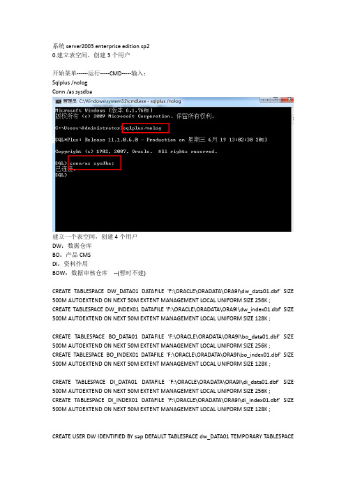
系统server2003 enterprise edition sp20.建立表空间,创建3个用户开始菜单------运行-----CMD-----输入:Sqlplus /nologConn /as sysdba建立一个表空间,创建4个用户DW:数据仓库BO:产品CMSDI:资料作用BOW:数据审核仓库--(暂时不建)CREATE TABLESPACE DW_DATA01 DATAFILE 'F:\ORACLE\ORADATA\ORA9I\dw_data01.dbf' SIZE 500M AUTOEXTEND ON NEXT 50M EXTENT MANAGEMENT LOCAL UNIFORM SIZE 256K ; CREATE TABLESPACE DW_INDEX01 DATAFILE 'F:\ORACLE\ORADATA\ORA9I\dw_index01.dbf' SIZE 500M AUTOEXTEND ON NEXT 50M EXTENT MANAGEMENT LOCAL UNIFORM SIZE 128K ;CREATE TABLESPACE BO_DATA01 DATAFILE 'F:\ORACLE\ORADATA\ORA9I\bo_data01.dbf' SIZE 500M AUTOEXTEND ON NEXT 50M EXTENT MANAGEMENT LOCAL UNIFORM SIZE 256K ; CREATE TABLESPACE BO_INDEX01 DATAFILE 'F:\ORACLE\ORADATA\ORA9I\bo_index01.dbf' SIZE 500M AUTOEXTEND ON NEXT 50M EXTENT MANAGEMENT LOCAL UNIFORM SIZE 128K ;CREATE TABLESPACE DI_DATA01 DATAFILE 'F:\ORACLE\ORADATA\ORA9I\di_data01.dbf' SIZE 500M AUTOEXTEND ON NEXT 50M EXTENT MANAGEMENT LOCAL UNIFORM SIZE 256K ; CREATE TABLESPACE DI_INDEX01 DATAFILE 'F:\ORACLE\ORADATA\ORA9I\di_index01.dbf' SIZE 500M AUTOEXTEND ON NEXT 50M EXTENT MANAGEMENT LOCAL UNIFORM SIZE 128K ;CREATE USER DW IDENTIFIED BY sap DEFAULT TABLESPACE dw_DATA01 TEMPORARY TABLESPACEtemp;GRANT connect,dba to DW;CREATE USER DI IDENTIFIED BY sap DEFAULT TABLESPACE di_DATA01 TEMPORARY TABLESPACE temp;GRANT connect,dba to DI;CREATE USER BO IDENTIFIED BY sap DEFAULT TABLESPACE bo_DATA01 TEMPORARY TABLESPACE temp;GRANT connect,dba to BO;1.装好oracle数据库后,安装BOE平台产品序列号:BOE2:BOE智能平台:CC20D-8GG4Z2S-ER0100J-VAUY仪表盘:CG206-HNTKW28-ERMSGFE-D8YT模拟分析:CN51C-8FG4Z2S-ERU0J8N-KKNU智能报表:B6W6G-31CSJV5-000A030-0CB0DI数据整合:CH21C-F5VKW24-ERUFBDN-05RF智能分析:不需要licenseE:\BO_2X-3X\BOE2-ENTERPRISE_1全名为计算机用户名然后一直下一步就开始安装了直到安装完成2.安装DI 产品(E:\BO_2X-3X\Data_services_XI_3.1\12.1.1.1\Win32\cdroot) 计算机名tt-biServer name是计算机名一直next 等待安装3.安装水晶易表(E:\BO_2X-3X\BOE2-CX\Xcelsius_2008_SP1\SP1)然后一直下一步,直到安装完成。

bnpm流程bnpm流程是一种基于npm的包管理工具,它的设计初衷是为了解决npm安装包时速度慢、网络不稳定等问题。
下面我将以人类的视角来描述bnpm的使用流程,并尽量使文章富有情感,让读者感受到真人的叙述。
我们需要明确一点,bnpm并不是一个独立的工具,而是在npm的基础上进行改进和优化。
它的目标是提供更快、更稳定的包安装和管理体验。
在正式开始使用bnpm之前,我们需要先安装它。
安装bnpm的方法非常简单,只需要在命令行中输入相应的安装命令即可。
安装完成后,我们就可以开始使用bnpm了。
使用bnpm的第一步是初始化一个新的项目。
在命令行中切换到项目所在的目录,然后运行`bnpm init`命令。
这个命令会创建一个新的`package.json`文件,用于记录项目的依赖信息和其他相关配置。
接下来,我们可以使用bnpm来安装项目所需的依赖包。
与npm类似,我们可以通过运行`bnpm install <package>`的命令来安装指定的包。
bnpm会根据`package.json`文件中的依赖信息,自动下载并安装所需的包。
安装完成后,我们可以在项目中引入这些包,并开始编写代码。
当我们需要更新项目的依赖包时,可以使用`bnpm update`命令来更新。
bnpm会根据`package.json`文件中的依赖信息,检查是否有新的版本可用,并自动更新已安装的包。
这样,我们就可以始终使用最新的包来开发我们的项目。
除了安装和更新包,bnpm还提供了其他一些有用的命令。
比如,我们可以使用`bnpm list`命令来查看当前项目中已安装的所有包;使用`bnpm search <keyword>`命令来搜索npm仓库中的包;使用`bnpm publish`命令来发布我们自己的包等等。
总的来说,bnpm是一个非常方便的包管理工具,它通过优化和改进npm的功能,提供了更快、更稳定的包安装和管理体验。
u启动u盘装系统教程借助U盘来安装操作系统是一种方便快捷的方法,本文将为大家提供一个500字的U盘装系统教程。
步骤一:准备工作首先需要一台具备制作U盘启动盘功能的电脑和一个容量大于8GB的U盘。
其次需要下载与你要安装的操作系统对应的系统镜像文件,确保操作系统与电脑硬件兼容。
步骤二:制作U盘启动盘将U盘连接到电脑上,然后打开电脑上的制作U盘启动盘的软件。
常用的软件有Rufus、UltraISO等。
选择正确的U盘和系统镜像文件,然后点击开始制作。
步骤三:设置启动项在制作完成后,将U盘插入要安装系统的电脑,并启动电脑。
同时按下电脑开机时显示的按键进入BIOS设置界面,一般是按下F2、Delete或者F12键。
步骤四:设置U盘为首选启动项在BIOS设置界面中,找到引导菜单或者启动选项,将U盘设置为首选启动项。
然后保存设置,并重新启动电脑。
步骤五:开始安装系统重启后,U盘会启动系统安装程序,根据系统安装界面的指引进行操作。
通常需要选择语言、系统版本、安装位置等。
这些选择根据个人需求和硬件配置进行设置。
步骤六:等待安装完成根据不同的操作系统和电脑配置,安装过程可能需要一段时间。
耐心等待直到安装完成。
步骤七:重启电脑安装完成后,电脑会自动重启。
此时可以拔掉U盘,然后按照系统需求进行一些必要的设置,例如设置管理员密码、网络连接等。
通过以上七个步骤,你就可以成功使用U盘来安装操作系统了。
这种方法可以节省安装时间和光盘资源,具有很大的便利性。
在日常使用中,我们也可以将U盘制作成多个系统启动盘,以备不时之需。
希望这个500字的U盘装系统教程能够对大家有所帮助!。
SCB10安装使用说明书SCB10安装使用说明书1. 介绍本文档旨在提供SCB10安装使用说明,为用户详细介绍SCB10的安装步骤和使用方法。
请按照本文档指导进行操作,以确保安装和使用的顺利进行。
2. 系统要求在安装和使用SCB10之前,请确保您的计算机系统满足以下要求:- 操作系统:(列出支持的操作系统及版本)- 处理器:(列出推荐的处理器类型和频率)- 内存:(列出推荐的内存容量)- 存储空间:(列出需要的磁盘空间)- 其他硬件:(如果有特定的硬件要求,请列出)3. 安装步骤3.1 SCB10安装程序在官方网站上最新版的SCB10安装程序,并保存到本地硬盘。
3.2 执行安装程序双击安装程序文件,按照提示进行安装。
在安装过程中,您可能需要选择安装目录和其他选项,根据需求进行设置。
3.3 完成安装等待安装程序完成所有必要的操作,安装过程可能需要一些时间。
安装完成后,您将收到安装成功的提示。
4. 配置设置在安装完成后,您需要进行一些配置设置,以确保SCB10能够正常运行。
4.1 连接数据库在首次运行SCB10之前,您需要连接到您的数据库服务器。
请提供正确的数据库连接信息(例如服务器地址、用户名和密码等),以便与数据库建立连接。
4.2 配置邮件服务器如果您需要使用SCB10的邮件功能,请配置正确的邮件服务器信息(例如SMTP服务器地址、用户名和密码等)。
4.3 其他配置根据您的实际需求,可以进行其他配置设置,例如界面语言、默认设置等。
5. 使用指南5.1 登录在安装和配置完成后,您可以使用您的用户名和密码登录SCB10系统。
5.2 主界面在登录后,您将看到SCB10的主界面。
主界面提供了各个功能模块的入口以及其他常用功能的快捷方式。
5.3 功能模块SCB10提供了各种功能模块,以支持不同的业务需求。
用户可以根据需要选择相应的功能模块进行操作。
5.4 操作流程针对每个功能模块,SCB10提供了详细的操作流程指导。
实验一【实验名称】SAP Business One的安装【目的与要求】1.确认计算机的安装环境(操作系统与数据库)2.掌握SAP Business One(BO或B1)的安装内容及安装步骤3.独立完成B1的标准安装与卸载;4.掌握B1运行,熟悉B1的基本模块及功能。
【实验内容】1.确认自己的笔记本电脑的操作系统(OS)及版本2.安装SQL数据库及补丁3.安装SAP Business One的三个内容:Server(服务器)、Server Tools(工具)、Client (客户端)4.正确进入SAP Business One5.熟悉SAP Business One的基本模块【方法与步骤】1.确认操作系统(OS)及版本鼠标右键点击“我的电脑”,确认操作系统为Win XP SP3,确认的结果是(1)满足实验环境的要求,进入SQL数据库的安装(2)重新安装操作系统的简单步骤;(3)升级补丁包的简单步骤;2.安装SQL 数据库(及SP3以上的补丁)3.安装SAP Business One启动SQL ,确保下面SAP BO服务器安装时能够连接到数据库使用虚拟光驱软件,加载SAP B1虚拟光驱文件,并进行下面各项的安装具体安装步骤按提示进行(1)安装SAP B1 Server注意安装的过程中采用Custom(自定义),选择需要的数据库实例(2)安装SAP B1 Server Tools安装成功后,计算机的程序菜单增加SAP Business One—>Server Tools —>Service Manager(3)安装SAP B1 Client安装成功SAP Business One菜单增加SAP Business One,并且桌面增加SAP Business One的快捷方式4.进入SAP Business One(1)启动数据库服务管理器(2)启动SAP Business One的Tools工具(3)启动SAP Business One的工具中的License manager 2005(4)双击桌面上的SAP Business One客户端程序的快捷方式或程序菜单中的SAP Business One进入SAP Business Onei.第一次进入输入系统默认的用户名和口令(manager),进入选择或新建公司界面;(若系统提示口令错,需要点击“选择公司窗口中的“更改服务器”,输入SQL的SA口令或点信任连接)选择公司后输入本地连接的IP地址:127.0.0.1后,进入SAP B1 ii.输入用户名和口令,直接进入上次退出SAP BO后的公司5.熟悉SAP Business One的功能模块菜单内容:模块的内容:【分析与思考】1.SAP BO与SQL数据库的关系2.SAP BO与SQL连接的注意事项3.SAP BO中Server、Server Tools、Client之间的关系4.SAP BO的功能模块包括企业哪些方面的业务5.安装体会【附录】。
Backup Exec备份实施1 .安装Backup Exec1.1安装BackupExec控制台将光盘插入光驱,屏幕中出现选择语言栏,选择简体中文,若没有自动提示,请运行光盘中的Browser.exe 文件。
选择预安装启动Backup Exec for Windows Servers环境检查点击BackupExec下一步选择本地环境检查,点击下一步。
查看是否满足安装环境,对未满足的使之能满足,其中Symantec防病毒检查、Symantec Endpoint Protection检查可以忽略,点击完成。
6)选择启动Backup Exec安装。
7)点击下一步选择本地安装,点击下一步。
9)点击下一步。
10)这里输入您购买的许可证密钥,点击下一步。
11)这里选择您所要安装代理的选件。
12)输入安装BE的路径,这里默认即可。
12)输入安装BE控制台计算机的密码,在这里即使本机的登录密码。
然后下一步13)在这里我们选择创建用来存储数据库的本地BackupExecSqlExpress,实例,点击下一步14)这里选择默认的方式,即所用磁带设备都是用Symantec的驱动,点击下一步。
16)点击安装,在此安装过程根据计算机配置的不同,所需的时间在15-30分钟左右。
在安装完成后,BE控制台也安装完毕。
1.2安装BE代理1)打开安装好的BE控制台选择工具,在工具栏中选择在其他服务器上安装代理和介质服务器。
点击添加,单个服务器。
选择远程产品Removte Agent for windows Systems.输入远程计算机IP、登录用户名和密码,点击下一步。
选择代理端安装的选项,选择RemoteAgent for Widows Systems.指定介质服务器的IP地址。
检查安装环境,然后下一步。
点击安装安装完成2.用户登录和服务启动2.1用户登录和创建用户在菜单栏选择“网络”→“登录账户”→“新建”或者“编辑”,弹出“登录凭证”对话框。