Sx300_IP-MAC_ACL_策略
- 格式:doc
- 大小:610.00 KB
- 文档页数:6


VSX-6114-V2 / VSX-6114-V2-AU DM&P Vortex86SX 300MHzTiny CPU Module with 4S/2USB/VGA/LVDS/LAN/GPIO128MB DDR2 OnboardUser’s Manual(Revision 1.0A)CopyrightThe information in this manual is subject to change without notice for continuous improvement in the product. All rights are reserved. The manufacturer assumes no responsibility for any inaccuracies that may be contained in this document. And makes no commitment to update or to keep current the information contained in this manual.No part of this manual may be reproduced, copied, translated or transmitted, in whole or in part, in any form or by any means without the prior written permission of the ICOP Technology Inc..©Copyright 2007 ICOP Technology Inc.Manual No. IUM6114-V2000-01 Ver.1.0A October, 2009Trademarks AcknowledgmentVortex86SX™ is the registered trademark of ICOP Technology Inc.Other brand names or product names appearing in this document are the properties and registered trademarks of their respective owners. All names mentioned herewith are served for identification purpose only.T a b l e o f C o n t e n t sT a b l e o f C o n t e n t s (iii)C h a p t e r 1 Introduction (1)1.1 Packing List (1)1.2 Product Description (1)1.3 Specifications (3)1.4 Board Dimension (5)C h a p t e r 2 Installation (6)2.1 Board Outline (6)2.2 Connectors & Jumpers Location (7)2.3 Connectors & Jumpers Summary (9)2.4 Pin Assignments & Jumper Settings (10)2.5 System Mapping (16)2.6 Watchdog Timer (19)2.7 GPIO (20)2.8 SPI flash (21)C h a p t e r 3 Driver Installation (22)Appendix (23)A. LVDS Flat Panel Support List (23)B. Flat Panel Wiring and Lighting (24)C. TCP/IP library for DOS real mode (25)D. BIOS Default Setting (26)Warranty (27)C h a p t e r 1 Introduction1.1 Packing ListProduct NamePackageVSX-6114-V2&VSX-6114-V2-AUEmbedded Vortex86SX CPU All-in-One BoardManual & Drivers CD x 1 RS232 cable x 4 IDE cable x 1USB cable x 1 (USB port x 2) VGA cable x 1 GPIO cable x 1 PS/2 Mouse cable x 1 PS/2 Keyboard cable x 11.2 Product DescriptionThe VSX-6114-V2 family of low-power x86 embedded controller is designed to meet Tiny specification, and integrated with the following features.300 MHz Vortex86SX System-On-Chip 128MB DDR2 system memoryVGA, LVDS LCD support up to1280x1024 resolutionEnhanced IDE (UltraDMA-100/66/33)10/100Mbps Ethernet2 USB 2.0 (host)Up to 4 serial ports16-bit GPIO x1x-ISA bus RS-485 with Auto Direction2 watchdog timerAudio (Optional)JTAG interfaceAMI BIOS2MB SPI flashSingle voltage +5V DCSupport extended operatingtemperature range of -20°C to +70°CThe VSX-6114-V2 Tiny family of embedded controller is designed with backward compatibility in mind, to provide migration path for projects facing end-of-life challenges with their existing x86 based Tiny controller. The VSX-6114-V2 family of controller is designed as a plug in replacement, with backward compatibility to support legacy software to help extend existing product life cycle without heavy re-engineering.VSX-6114-V2 is suitable for broad range of data-acquisition, Industrial automation, Process control, Automotive controller, AVL, Intelligent Vehicle management devic,Medical device, Human machine interface, Robotics, machinery control And more…application that required small footprint, low-power and low-cost hardware with open industry standard such asTiny.1.3 SpecificationsFeatures VSX-6114-V2CPUDM&P SoC CPU Vortex86SX- 300MHzReal Time Clock with Lithium Battery Backup Cache L1:16K I-Cache, 16K D-Cache BIOSAMI BIOSBus Interface 16-bit x-ISA interface System Memory 128 / 256MB DDR2 OnboardWatchdog Timer Software programmable from 30.5 us to 512 seconds x2sets(Watchdog 1 fully compatible with M6117D) VGAXGI Volari Z9s ChipsetVGA and LVDS Flat Panel Interface Support Onboard 32MB VGA MemorySupport resolution up to 1280 x 1024,16MB colorsLAN Integrated 10/100M EthernetAudioCM119 USB Audio Controller (Optional) I /O InterfaceEnhanced IDE port (UltraDMA-100/66/33) x1 RS-232 port x3RS-232/422/485 port x1(RS485 with Auto Direction) USB port x2 (USB 2.0 version) 16-bit GPIO port x110/100Mbps Ethernet port x1Connectors2.00 mm ∅ 44-pin box header for IDE x12.00 mm ∅ 20-pin box header for 16-bit GPIO x1 2.00 mm ∅ 10-pin box header for RS-232 x4 2.00 mm ∅ 10-pin box header for USB x1 2.00 mm ∅ 10-pin box header for VGA x1 2.00 mm ∅ 16-pin header for LVDS x 1 2.54 mm ∅ 3-pin header for RS-485 x1 2.54 mm ∅ 5-pin header for keyboard x1 2.54 mm ∅ 5-pin header for Mouse x1 2.54 mm ∅ 2-pin header for Reset x1 1.25 mm ∅ 6-pin wafer for JTAG x11.25 mm ∅ 4-pin wafer for Line-out/MIC-in x2 (Opt.)External RJ-45 connector for Ethernet x1Flash Disk SupportOnboard 2MB SPI Flash Disk (Driver: A)44-pin IDE Flash Disk( EmbedDisk 16MB or above)Power Requirement Single Voltage +5V @ 620mA Dimension 100mm X 66mm (3.94 x2.6 inches) Weight 65gOperating Temperature -20o C ~ +70o C-40°C ~ +85°C (Optional)1.4 Board DimensionC h a p t e r 2Installation2.1 Board Outline(Note1: COM2 RS232/422/485 is selected by BIOS setting) (Note2: Audio is optional)2.2 Connectors & Jumpers Location ConnectorsJumpers & LEDs2.3 Connectors & Jumpers SummarySummary TableNbr Description Type of Connections Pinnbrs.J1 IDE Box Header, 2.0∅ ,22x2 44-pinJ2 USB Box Header,2.0∅ , 5x2 10-pinJ4 10/100Base-T Ethernet LAN RJ45 Connector 8-pinJ5 JTAG Wafer, 1.25∅ , 6x16-pinJ8 PS/2 Keyboard Box Header, 2,54∅,1x5 5-pinJ9 Buzzer Pin Header, 2,54∅,1x2 2-pinJ10 PS/2 Mouse Pin Header, 2,54∅,1x5 5-pinJ11 COM1 Box Header, 2.0∅ 5x2 10-pinJ12 COM2 Box Header, 2.0∅ 5x2 10-pinJ13 GPIO Port 0 / 1 Box Header, 2.0∅ ,10x2 20-pinJ15 RS-485 Molex Header,2.54∅,3x1 3-pinJ16 Reset Pin Header, 2,54∅,1x2 2-pinJ17 Power Connector Terminal Block 5.0∅,2x1 2-pinJ18 COM3 Box Header, 2.0∅ 5x2 10-pinJ19 COM4 Box Header, 2.0∅ 5x2 10-pinJ20 x-ISA Connector – 64 pin Box Header, 2.54∅ 32x2 64-pinJ21 VGA Pin Header, 2.0∅ ,5x2 10-pinJ22 LVDS Pin Header, 2.0∅ 8x2 16-pinJ23 LINE-OUT (Optional)Wafer, 1.25∅ , 4x14-pinJ24 MIC-IN (Optional)Wafer, 1.25∅ , 4x14-pin PWR-LED Power Active LED (Red) LED-SMDIDE- LED IDE Active LED (Green ) LED-SMDLED 3 LAN Link/Active LCD (Green) LED-SMDLED 4 LAN Duplex LED ( Yellow ) LED-SMD2.4 Pin Assignments & Jumper Settings J1: IDE (44 Pins)J2: USB Pin # Signal Name Pin # Signal Name1 VCC2 VCC3 LUSBD3-4 LUSBD2-5 LUSBD3+6 LUSBD2+7 GND8 GND9 GGND 10 GGNDJ5: JTAGPin # Signal Name Pin # Signal Name1 VCC2 GND3 TCK4 TDO5 TDI6 TMS Pin # Signal Name Pin # Signal Name1 IDERST2 GND3 IDED74 IDED85 IDED6 6 IDED97 IDED58 IDED109 IDED4 10 IDED11 11 IDED3 12 IDED12 13 IDED2 14 IDED13 15 IDED1 16 IDED14 17 IDED0 18 IDED15 19 GND 20 NC 21 IDEREQ 22 GND 23 IDEIOW 24 GND 25 IDEIOR 26 GND 27 ICHRDY 28 GND 29 IDEACK 30 GND 31 IDEINT 32 NC 33 IDESA1 34 IDECBLID 35 IDESA0 36 IDESA2 37 IDECS-0 38 IDECS1 39 IDELED 40 GND 41 VCC 42 VCC 43 GND 44 NCJ8: PS/2 KeyboardPin # Signal Name Pin # Signal Name1 KBCLK2 KBDAT3 NC4 GND5 VCCJ9: BuzzerPin # Signal Name Pin # Signal Name1 Buzzer2 VCCJ10: PS/2 MousePin # Signal Name Pin # Signal Name1 MSCLK2 MSDATA3 NC4 GND5 VCCJ11: COM 1Pin # SignalNamePin #SignalName1 DCD12 RXD13 TXD14 DTR15 GND6 DSR17 RTS1 8 CTS19 RI1 10 NCJ12: COM2 RS232 / 422 / 485 (Change setting by BIOS) Pin # Signal Name Pin # Signal Name1 DCD2/ 422TX- / RS485-2 RXD2 / 422TX+ / RS485+3 TXD2 / 422RX+4 DTR2 / 422RX-5 GND6 DSR27 RTS28 CTS29 RI2 10 NCJ13: GPIO (Port 0 / Port 1)J15: RS-485 (Auto direction)Pin # Signal Name Pin # Signal Name1 GND2 VCC3 GP004 GP105 GP016 GP117 GP028 GP129 GP03 10 GP1311 GP04 12 GP14 13 GP05 14 GP15 15 GP06 16 GP1617 GP07 18 GP17 19 VCC 20 GND Pin # Signal Name1 RS485+2 RS485-3 GNDJ16: RESETPin # Signal Name Pin # Signal Name1 Reset2 GNDJ17: Power Connector (Terminal Block 5.0mm) Pin # Signal Name1 +5V2 GNDJ18: COM3Pin # Signal Name Pin # Signal Name1 DCD32 RXD33 TXD34 DTR35 GND6 DSR37 RTS3 8 CTS39 RI3 10 NCJ19: COM4Pin # Signal Name Pin # Signal Name1 DCD42 RXD43 TXD4 4 DTR45 GND6 DSR47 RTS4 8 CTS49 RI4 10 NCJ20: x-ISA Connector – 64pinPin # Signal Name Pin # Signal Name1 GND2 SBHE3 RSTDRV4 SD75 VCC6 SD67 SD8 8 SD510 SD49 SD911 SD10 12 SD313 SD11 14 SD215 SD12 16 SD117 SD13 18 SD0IOCHRDY19 GND 2021 SMEMW 22 AEN23 SMEMR 24 SA1925 IOW 26 SA1827 IOR 28 SA1729 SD14 30 SA1631 SD15 32 SA1533 MEMCS16 34 SA1435 ICOS16 36 SA1337 REFRESH 38 SA1239 SYSCLK 40 SA1141 IRQ7 42 SA1043 IRQ6 44 SA945 IRQ5 46 SA847 IRQ4 48 SA749 IRQ3 50 SA651 IRQ10 52 SA553 IRQ11 54 SA455 BALE 56 SA357 VCC 58 SA259 OSC 60 SA161 GND 62 SA063 IRQ12 64 IRQ14J21: VGAPin # SignalNamePin #SignalName1 ROUT 2 GND3 GOUT 4 GND5 BOUT 6 GND7 HSYNC 8 GND9 VSYNCD 10 GNDJ22: LVDSPin # Signal Name Pin # Signal Name1 VCC3(+3.3V) 2 VCC3(+3.3V)3 GND4 GND5 RxIN0+6 RxIN0-7 RxIN1- 8 GND9 GND 10RxIN1+11 RxIN2+ 12 RxIN2-13 CKIN- 14 GND15 GND 16 CKIN+J23: LINE OUT (Optional)Pin # Signal Name1 LOUTR2 GND3 GND4 LOUTLJ24: MIC-IN (Optional)Pin # Signal Name1 MICVREF2 GND3 GND4 MIC-IN2.5 System Mapping2.6 Watchdog TimerThere are two watchdog timers in Vortex86SX/DX CPU. One is compatible with M6117D watchdog timer and the other is new. The M6117D compatible watchdog timer is called WDT0 and new one is called WDT1.We also provide DOS, Linux and WinCE example for your reference. For more technical support, please visit: /tech or download the PDF file:/tech/vortex86dx/2.7 GPIO (General Purpose Input / Output)40 GPIO pins are provided by the Vortex86SX/DX for general usage in the system. All GPIO pins are independent and can be configured as inputs or outputs, with or without pull-up/pull-down resistors.We also offer DOS, Linux and WinCE example for your reference. For more technical support, please visit: /tech or download the PDF file:/tech/vortex86dx/2.8 SPI flash (Serial Peripheral Interface)As SPI Flash (Serial Peripheral Interface) offers many benefits including: reduced controller pin count, smaller and simpler PCBs, reduced switching noise, less power consumption, and lower system costMany of users may consider using a formatted SPI flash to boot for the system or emulate SPI flash as Floppy (A: Driver or B: Driver). Then you must know how to set for this condition in CMOS Setup and boot up under DOS 6.22, X-DOS, DR-DOS and Free DOS.For more technical support, please visit: /tech or download the PDF file: /tech/vortex86dx/C h a p t e r 3Driver InstallationVGAThe Vortex86SX processor also use external Display chip ““Volari™ Z9s” which is an ultra low powered graphics chipset with total power consumption at around 1-1.5 W. It is capable in providing VGA display output upto 1600x1200. With DVO interface, developers could easily connect flat Panel to support TFT and LVDS output.LANThe Vortex86SX processor integrated 10/100Mbps Ethernet controller that supports both 10/100BASE-T and allows direct connection to your 10/100Mbps Ethernet based Local Area Network for full interaction with local servers, wide area networks such as the Internet.I/O and IRQ settings can be done by software with the supplied utility software, or it can be set for Plug and Play compatibility. The controller supports: Half / Full-Duplex Ethernet function to double channel bandwidth, auto media detection.Operating system supportThe Vortex86SX-6114-V2 Tiny CPU board provides the VGA and LAN drivers for DOS 6.22 Windows CE 5.0 and Windows Embedded CE 6.0. Please get the drivers from the Driver CD which attached with the standard packing of Vortex86SX-6114-V2 board or please get it from DMP official website: /tech/vortex86sx/ .Vortex86SX-6114-V2 also supports most of the popular Linux distributions, for more detail information, please visit DMP official website: /tech/vortex86sx/.AppendixA. LVDS Flat Panel SupportSize Brand Resolution Model No.3.5” PVI 640x480 PD035VL15” PVI 640x480 PD050VL16.5” AUO 640x480 G065VN018.4” AUO 800x600 G084SN038.9” AUO 1024x600 A089SW018.9” CPT 1024x600 CLAA089NA0ACW8.9” HannStar 1024x600 HSD089IFW110” HannStar 1024x600 HSD100IFW1-A0010.4” MITSUBISHI 800x600 AA104SG0110.4” AUO 800x600 G104SN0210.4” Sharp 800x600 LQ104S1LG6112.1” MITSUBISHI 800x600 AA121SL0312.1” AUO 800x600 G121SN0115” AUO 1024x768 G150XG01B. Flat Panel Wiring and LightingHardwareBefore you connect the LVDS LCD Flat Panel with Vortex86SX-6114-V2, please makesure that the input Voltage of LCD is +3.3V or NotBIOSPlease contact or e-mail our regional sales to get the special BIOS for any LVDS LCDFlat Panels.Wiring LCD CablePlease refer to Page 15 (J22: LVDS connector) and Page 23~24. Or for more LCD lighting and integration service, please contact our regional sales or mail to *************.tw ,if you have any questions.C. TCP/IP library for DOS real modeDSock is a TCP/IP library for DOS real mode, which is used by RSIP. It provides simple C functions for programmer to write Internet applications. ICOP also provide Internet examples using DSock: BOOTP/DHCP, FTP server, SMTP client/server, HTTP server, TELNET server, Talk client/server, etc.DSock provides a lot of example source code. Programmer can add Internet functions to their project easily and save development time. With a utility "MakeROM”, programmer also can make a ROM image to fit their application, those examples can be seen in the following Application systems: Mity-Mite Serial Server,Web Camera Tiny Server and RSIP Serial Server.DSock is free for All ICOP products using M6117D/Vortex86/Vortex86SX/Vortex86DX CPU and ICOP also provide the business version of DSock for those customers who are using other x86 CPUs.If you would like to use DSock or business version of DSock, Please mail to *************.tw or contact your regional sales.Please download the trial DSock software and Utilities from our website:/tech/dmp-lib/dsock/D. BIOS Default settingIf the system cannot be booted after BIOS changes are made, Please follow below procedures in order to restore the CMOS as default setting.Press “End” Key, when the power onPress <Del> to enter the AMI BIOS setupPress “F9” to Load Optimized DefaultsPress “F10” to Save configuration changes and exit setupWarrantyThis product is warranted to be in good working order for a period of one year from the date of purchase. Should this product fail to be in good working order at any time during this period, we will, at our option, replace or repair it at no additional charge except as set forth in the following terms. This warranty does not apply to products damaged by misuse, modifications, accident or disaster. Vendor assumes no liability for any damages, lost profits, lost savings or any other incidental or consequential damage resulting from the use, misuse of, originality to use this product. Vendor will not be liable for any claim made by any other related party. Return authorization must be obtained from the vendor before returned merchandise will be accepted. Authorization can be obtained by calling or faxing the vendor and requesting a Return Merchandise Authorization (RMA) number. Returned goods should always be accompanied by a clear problem description.。

ACL配置本手册著作权属迈普通信技术有限公司所有,未经著作权人书面许可,任何单位或个人不得以任何方式摘录、复制或翻译。
侵权必究。
策划:研究院资料服务处* * *迈普通信技术有限公司地址:成都市高新区九兴大道16号迈普大厦技术支持热线:400-886-8669传真:(+8628)85148948E-mail:******************.com网址:邮编:610041版本:2011年 8月v1.0版目录第1章 ACL配置 (4)1.1 ACL简介 (4)1.1.1 ACL的匹配顺序 (4)1.1.2 支持的ACL (5)1.2 配置时间段 (6)1.2.1 配置过程 (6)1.2.2 配置举例 (7)1.3 定义基本ACL (8)1.3.1 配置过程 (8)1.3.2 配置举例 (9)1.4 定义扩展ACL (9)1.4.1 配置过程 (9)1.4.2 配置举例 (11)1.5 定义二层ACL (12)1.5.1 配置二层ACL (12)1.5.2 配置举例 (13)1.6 激活ACL (13)1.6.1 激活ACL (13)1.6.2 配置举例 (14)1.7 ACL的显示和调试 (15)第1章ACL配置1.1 ACL简介ACL(Access Control List,访问控制列表)主要用来实现流识别功能。
网络设备为了过滤数据包,需要配置一系列的匹配规则,以识别需要过滤的对象。
在识别出特定的对象之后,才能根据预先设定的策略允许或禁止相应的数据包通过。
ACL根据一系列的匹配条件对数据包进行分类,这些条件可以是数据包的源地址、目的地址、端口号等。
交换机根据ACL中指定的条件来检测数据包,从而决定是转发还是丢弃该数据包。
由ACL定义的数据包匹配规则,还可以被其它需要对流进行区分的场合引用,如QoS 中流分类规则的定义。
根据应用目的,可将ACL 分为下面几种:●基本ACL:只根据源IP地址制定规则。

摘要: 本文从校园网络保障体系、校园网络环境建设、教学资源和校园网络应用等四个环节来探讨校园网络建设策略。
其目的是:第一,在微观上切实保证校园网的顺利建成并发挥其应有的作用,实现促进教学改革、培养信息社会所需人才的最终目标。
第二,在宏观上把握正确的校园网络建设方向,制定行之有效的建网、护网和用网的实施方案;关键词:校园网络建设管理应用规划设计目录一、校园网络整体概括 (1)(一)第七中学概况 (1)(二)校园网络需求分析 (2)(三)网络相关技术分析 (2)(四)校园网络建设的内容: (2)二、总体设计原则 (3)三、校园网络建设方案 (3)(一)校园网建设方案概述 (3)(二)校园网络结构分析及VLAN划分 (4)1、校园网络结构分析 (4)2、校园网络拓扑结构 (5)3、校园网采用的网络操作系统 (5)4、络设备选型 (6)5、络接入选择 (9)6、VLAN划分 (9)四、综合布线设计 (10)(一)........................................... 布线系统分析10(二)............................................. 布线系统总体结构11(三)........................................... 结构化布线系统11 五、在施工中注意事项 . (15)(一)工程施工前准备 (15)(二)综合布线系统施工方案 (16)1、线缆的敷设 (17)2、线缆的端接 (18)3、信息插座的安装及端接 (18)(三)最后验收 (19)六、校园网建设工程预算 (20)七、总结 (22)参考文献: (22)、校园网络整体概括近年来,校园网络的建设在中学掀起一股热潮,许多中学都建起了自己的校园网,形成了一个覆盖全国的计算机网并通过专线与Internet 连通。
这一方面加强了学校与国内外的联系,有利于及时了解国内的信息,有助于提高学校的科研教学水平;另一方面,校园网的建立及以其为基础的管理信息系统的开发,也有利于各学校管理水平的提高。
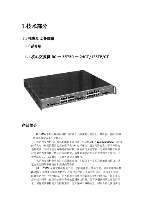
1.技术部分1.1网络及设备部份1产品介绍1.1核心交换机RG一55750一24GT/12SFP/GT产品简介RG-S5750系列是锐捷网络推出的融合了高性能、高安全、多智能、易用性的新一代万兆机架式多层交换机。
该系列交换机接口形式和组合非常灵活,可提供24个10/100/1OOOM自适应的千兆电口和灵活复用的高密度千兆SFP光纤连接,满足网络建设中不同介质的连接需要。
同时为满足网络的弹性扩展,和高带宽传输需要,可灵活弹性扩展多种类型的万兆模块。
特别适合高带宽、高性能和灵活扩展的大型网络汇聚层,中型网络核心,以及数据中心服务器接入的使用。
该系列交换机硬件支持多层线速交换,并提供了丰富而完善的路由协议,以适合大型网络多种路由和高性能的需要。
RG一55750系列交换机提供二到七层的智能的业务流分类、完善的服务质量(QoS)保证和组播应用管理特性。
在提供高性能、多智能的同时,其内在的安全防御机制和用户管理能力,更可有效防止和控制病毒传播和网络攻击,控制非法用户接入网络,保证合法用户合理地使用网络资源,并可以根据网络实际使用环境,实施灵活多样的安全控制策略,充分保障了网络安全、网络合理化使用和运营。
RG一55750系列交换机以极高的性价比为大型网络汇聚、中型网络核心、数据中心服务器接入提供了高性能、完善的端到端的服务质量、灵活丰富的安全设置和基于策略的网管,最大化满足高速、安全、智能的校园网需求。
适用场合适用大型网络的汇聚层、中小型网络的核心、服务器群的接入,适用需要多的千兆端口数、需要高性能多层交换解决方案的场合。
具有丰富的安全管理机制,提供网络安全防御、高安全接入控制和有效网络访问控制。
具有完善的管理策略应用,帮助管理带宽、保证语音、组播音视频服务及视频点播等关键任务的应用。
通过简单地增加万兆模块即可以平滑地升级为万兆上链骨干网。
产品特性具有高性能多层交换能力。
具有高背板带宽为所有的端口提供非阻塞的性能;丰富完善的路由性能和超大容量路由表资源可满足大型网络动态路由的需要,特别是支持ECMP/WCMP(Equal一CostMultipathRouting/Weight一CostMultipathRoutiflg),确保了各骨干网络链路的充分使用,大大增加了网络传输带宽,而且司以无时延无丢包地备份失效链路的数据传输。

Sx300 升级固件
编者:warren.chen
时间:2012-7-9
版本:1.0
此实验将SX300 交换机由初始固件1.0.0.27 升级到1.1.2.0 并有中文语言包。
实验注意:升级固件时版本由1.0.0.27 –1.0.0.73—1.1.1.8—1.1.2.0- 中文语言包1.1.1.6 要逐版本升级不要跳级。
在每次版本升级后要激活及重启设备。
1.查看当前版本:1.0.0.27
2.官方网站下载1.1.0.73 固件。
3.File management-upgrade/backup firmware /languare 升级固件。
4.升级成功
5.要重启设备
6.激活新固件1.0.0.73
7.激活成功并查看
8.官方网站下载固件1.1.1.8
9.升级新固件1.1.1.8
10.升级成功
11.激活固件1.1.1.8
12.重启设备
13.查看激活固件1.1.18
14.官方下载固件1.1.2.0
15.升级新固件1.1.2.0
16.升级成功
17.重启设备
18. 激活固件1.1.2.0
19. 重启设备
20. 查看激活后的固件1.1.2.0
21. 官方网站下载中文语言包ng
22. 升级语言包
23. 升级成功
24. 重启设备
25.查看当前的固件1.1.2.0 中文界面。
流量控制配置
Q:如何控制用户的下载速度,如:接入带宽50M,工作组的用户共使用20M 带宽,每个用户下载速度控制在200KB/S。
第一步,登陆管理界面,打开“网络配置”-“线路配置”,将WAN口带宽按照实际接入带宽设置好,如宽带线接在WAN0口,设置WAN0口上行50M,下行50M,即可。
第二步,打开“流量控制”勾选“启用流控功能”添加流控策略配置
流控策略配置:勾选“通道启用”,设置通道名称,设置通道带宽分配为上下行均为20M,再打开“用户应用类型匹配条件”如图:
选择用户应用类型匹配条件:启用用户应用匹配条件,实施对象选择工作组,应用类型选择全部应用,网站类型选择全部url类型。
点击“确定”保存即完成对工作组所有用户总带宽
为20M的配置。
上行,下行限制设置为4%,即2M,其他参数使用默认配置。
点击“确定”。
为10000,上下行均设置为200KB/S。
点击确定即完成对每个用户下载控制。
iSpirit 3524G/F交换机常用配置指南(软件版本:iSpirit3524g2v20.img iSpirit3524f2v00.img)(Version 1.0)2004年11月一.基于PORT(端口)的VLAN配置 (3)二.基于802.1Q的VLAN配置 (6)三.VLAN间通信配置 (9)四.STP(生成树协议配置) (19)四.TRUNK 端口聚合 (22)五.MIRROR (端口镜像)配置 (23)六.CONFIGURATION文件上传(备份)和下载配置 (25)七.IMAGE版本升级 (26)八.SNMP配置 (27)九.DHCP RELAY 配置 (30)十.802.1X认证 (31)十一.ACL访问控制列表配置 (34)十二.静态路由 (46)十四.IP配置 (49)附件:配置超级终端 (50)一.基于PORT(端口)的VLAN配置1. 网络需求有两个用户,用户1和用户2,两个用户由于所使用的网络功能和环境不同,需要分别处于不同的VLAN中。
用户1在VLAN2,连接3524G的端口2,用户2在VLAN3,连接端口3。
2. 配置步骤Switch# vlan 2 // 创建vlan 2Vlan 2 addedSwitch(vlan-2)#exitSwitch# vlan 3 // 创建vlan 3Vlan 3 addedSwitch(vlan-3)# vlan 2 // 在创建vlan 2 之后,就可在配置模式下 输入vlan 2 ,进入vlan 2的配置模式Switch(vlan-2)# untag 2 // 将端口2 加入vlan 2,如果还有其它端口要加入vlan 2,那么在 vlan 2 模式下,untag x (x为其它端口号)Switch(vlan-2)# vlan 3 //进入vlan 3 配置模式Switch(vlan-3)# untag 3 //将端口3 加入vlan 3,如果还有其它端口要加入vlan 3,那么在 vlan 3 模式下,untag x (x为其它端口号)Switch(vlan-3)# exit// 注意:本例子中,由于使用的软件版本是2v.00以上(含2v.00),所以pvid 号随着vlan号的更改而自动更改的。
Sx300 交换机IP / MAC ACL 策略
拓朴图及描述: sx300 交换机PC1 连接端口7, PC2 连接端口8 。
PC1- 192.168.1.100 PC2: 192.168.1.200
PC2
1. Access Control
IPV4-Based ACL 添加 ACL1 。
点击 IPv4-Based ACE Table
2.添加ACL 策略
Priority : 优先级:数字小优先级高
Action: permit 允许deny: 拒绝shutdown : 关掉端口Protocol: 协议any IP 或是特定的协议
Source IP address value: 192.168.1.100
Source ip wildcard mask: 0.0.0.255 子码反掩码3.ACL 绑定ACL Binding
将ACL1 这条策略应用到8 端口
4.验证:
在ACL1 策略没有应用到8端时是通信的。
将ACL1 策略应用到8端口时无法通信
5.总结:
分三步:1. 创建ACL 名字。
2.添加策略规则 3.应用到端口
MAC ACL 拓朴图与上面的IP ACL 一样
1.创建ACL2-MAC
点击MAC-Based ACE Table
3.添加ACL 规则
参数与上面的IP ACL 是一样的,只是IP 改为MAC 地址。
Destination MAC Address V alue: 00:24:1d:bc:7d:65
Destination mac wildcard mask: 00:00:00:00:00:00 注意这也是反码表示,只有这一个MAC 地址。
4.验证:
在没有应用ACL2-MAC 到端口7时是可以通信的。
在将ACL2-MAC 应用到端口7时无法通信。
总结:
6.总结:
分三步:1. 创建ACL 名字。
2.添加策略规则 3.应用到端口。