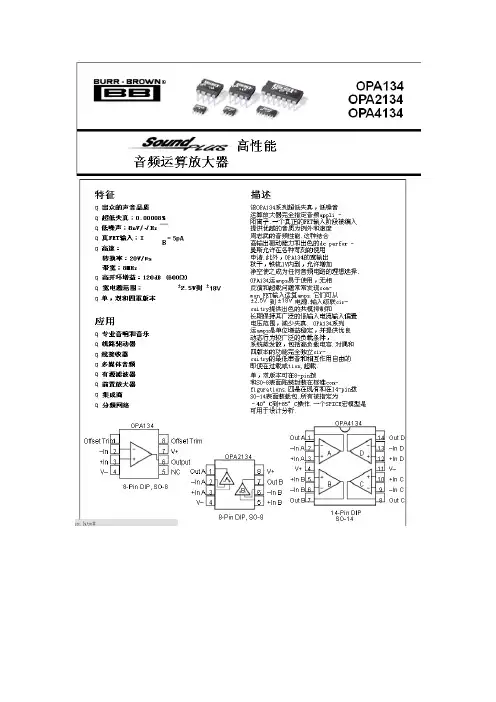
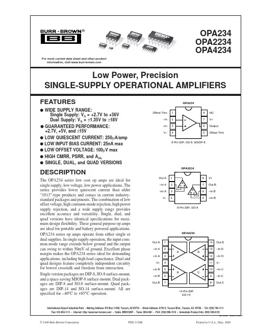
opa2134详细中文资料
- 格式:doc
- 大小:1.34 MB
- 文档页数:10
几款发烧运放听感测试报告几款发烧运放听感测试报告写在前面的话:5年前写的了,现在翻出来,还是觉得有些小用,正好朋友聊起,就发了。
陆续用了一个月多时间,前后间隔三个呀,写下一些文字,名为运放听感测试报告。
虽然希望尽力给爱摩机的朋友带来一点参考,但是设备极其有限、器材相当匮乏,所以更多的也只能是一种基于爱好的相互交流。
说起来难以使人相信,从2001年入手帝盟S100开始算作发烧初始,但是一直没有真正像样一点儿的器材。
07年6,然后11月入手乐之邦玲珑3纪念版,于是一发不可收拾,接着入手HIFIDIY MINI USB DAC,再接着是甩二——我不可挽回的中毒了,为了使MINI SUB DAC和甩二工作得更好,我玩起了运放……在各类发烧器材店蹭听总计不到10小时算是熟悉器材。
08年8无损成为这次测试的音源。
本次评测目的是理性了解各个运放的特点,因此,测试者的主观认识、测试条件,就像物理学里的参照系一样重要。
所有评测以HIFIDIY MINISUB DAC增强电源打摩版(将数字、模拟部分共7粒nichicon 滤波电解换为思碧轴向钽电解电容)为基准设备,DAC的I/V变换、LPF和放大同时使用相同的两对OP,并参考用作甩二SE输出运放的表现。
基准测试器材是ThinkPadT61+HIFIDIY MINI USB DAC+HD590,参考测试是台电T39+StreetWires ZN73.5toRCA+SXT-2+HD590&foobar0.955+帝盟S100+StreetWires ZN73.5toRC+SXT-2+HD590,搭配性测试器材是森海MX760、达音科S01、舒尔E4C、EC700 by lilelelee。
播放器为foobar0.955中文版,插件为音源为60%的人声、30%的器乐、10%的交响和古典,第一次随机选取,以后每次按第一次播放列表顺序播放。
所有评测均有相当音量(终端输出器材的音量均在8点到11点)以保证足够的声压,并用DT9205A万用表测量,使得每次同一终端输出器材1KHz下开环输出电压一致。

1.General descriptionThe LPC2131/32/34/36/38 microcontrollers are based on a 16/32-bit ARM7TDMI-S CPU with real-time emulation and embedded trace support, that combine the microcontroller with 32kB, 64kB, 128kB, 256kB and 512 kB of embedded high-speed flash memory. A 128-bit wide memory interface and a unique accelerator architecture enable 32-bit code execution at maximum clock rate.For critical code size applications,the alternative 16-bit Thumb mode reduces code by more than 30% with minimal performance penalty.Due to their tiny size and low power consumption, these microcontrollers are ideal for applications where miniaturization is a key requirement, such as access control and point-of-sale. With a wide range of serial communications interfaces and on-chip SRAM options of 8kB, 16kB, and 32kB, they are very well suited for communication gateways and protocol converters, soft modems, voice recognition and low-end imaging, providing both large buffer size and high processing power. Various 32-bit timers, single or dual 10-bit 8-channel ADC(s), 10-bit DAC, PWM channels and 47 GPIO lines with up to nine edge or level sensitive external interrupt pins make these microcontrollers particularly suitable for industrial control and medical systems.2.Features2.1Enhancements brought by LPC213x/01 devicesI Fast GPIO ports enable port pin toggling up to 3.5 times faster than the original LPC213x. They also allow for a port pin to be read at any time regardless of its function.I Dedicated result registers for ADC(s) reduce interrupt overhead.I UART0/1 include fractional baud rate generator, auto-bauding capabilities and handshake flow-control fully implemented in hardware.I Additional BOD control enables further reduction of power consumption.2.2Key features common for LPC213x and LPC213x/01I 16/32-bit ARM7TDMI-S microcontroller in a tiny LQFP64 or HVQFN package.I 8/16/32kB of on-chip static RAM and 32/64/128/256/512kB of on-chip flash program memory. 128-bit wide interface/accelerator enables high-speed 60MHz operation.I In-System Programming/In-Application Programming (ISP/IAP)via on-chip bootloader software.Single flash sector or full chip erase in 400ms and programming of 256B in 1 ms.I EmbeddedICE RT and Embedded T race interfaces offer real-time debugging with the on-chip RealMonitor software and high-speed tracing of instruction execution.LPC2131/32/34/36/38Single-chip 16/32-bit microcontrollers; 32/64/128/256/512kB ISP/IAP flash with 10-bit ADC and DACRev. 04 — 16 October 2007Product data sheetI One (LPC2131/32) or two (LPC2134/36/38) 8-channel 10-bit ADCs provide a total ofup to 16 analog inputs, with conversion times as low as 2.44µs per channel.I Single 10-bit DAC provides variable analog output (LPC2132/34/36/38).I T wo 32-bit timers/external event counters (with four capture and four comparechannels each), PWM unit (six outputs) and watchdog.I Low power Real-time clock with independent power and dedicated 32 kHz clock input.I Multiple serial interfaces including two UARTs(16C550),two Fast I2C-bus(400kbit/s),SPI and SSP with buffering and variable data length capabilities.I Vectored interrupt controller with configurable priorities and vector addresses.I Up to forty-seven 5V tolerant general purpose I/O pins in tiny LQFP64 or HVQFNpackage.I Up to nine edge or level sensitive external interrupt pins available.I60MHz maximum CPU clock available from programmable on-chip PLL with settling time of 100µs.I On-chip integrated oscillator operates with external crystal in range of 1MHz to30MHz and with external oscillator up to 50MHz.I Power saving modes include Idle and Power-down.I Individual enable/disable of peripheral functions as well as peripheral clock scalingdown for additional power optimization.I Processor wake-up from Power-down mode via external interrupt or BOD.I Single power supply chip with POR and BOD circuits:N CPU operating voltage range of 3.0V to 3.6V (3.3V± 10%) with 5V tolerant I/Opads.3.Ordering informationTable 1.Ordering informationType number PackageName Description Version LPC2131FBD64LQFP64plastic low profile quad flat package; 64 leads;SOT314-2body 10×10×1.4mmSOT314-2 LPC2131FBD64/01LQFP64plastic low profile quad flat package; 64 leads;body 10×10×1.4mmSOT314-2 LPC2132FBD64LQFP64plastic low profile quad flat package; 64 leads;body 10×10×1.4mmLPC2132FBD64/01LQFP64plastic low profile quad flat package; 64 leads;SOT314-2body 10×10×1.4mmSOT804-2 LPC2132FHN64HVQFN64plastic thermal enhanced very thin quad flatpackage; no leads; 64 terminals; body9×9×0.85mmSOT804-2 LPC2132FHN64/01HVQFN64plastic thermal enhanced very thin quad flatpackage; no leads; 64 terminals; body9×9×0.85mmSOT314-2 LPC2134FBD64LQFP64plastic low profile quad flat package; 64 leads;body 10×10×1.4mmLPC2134FBD64/01LQFP64plastic low profile quad flat package; 64 leads;SOT314-2body 10×10×1.4mm3.1Ordering optionsLPC2136FBD64LQFP64plastic low profile quad flat package; 64 leads;body 10×10×1.4mmSOT314-2LPC2136FBD64/01LQFP64plastic low profile quad flat package; 64 leads;body 10×10×1.4mmSOT314-2LPC2138FBD64LQFP64plastic low profile quad flat package; 64 leads;body 10× 10×1.4mmSOT314-2LPC2138FBD64/01LQFP64plastic low profile quad flat package; 64 leads;body 10× 10×1.4mmSOT314-2LPC2138FHN64HVQFN64plastic thermal enhanced very thin quad flatpackage; no leads; 64 terminals; body 9×9×0.85mmSOT804-2LPC2138FHN64/01HVQFN64plastic thermal enhanced very thin quad flatpackage; no leads; 64 terminals; body 9×9×0.85mmSOT804-2Table 1.Ordering information …continuedType number Package NameDescriptionVersion Table 2.Ordering optionsType numberFlash memory RAM ADCDACEnhanced UARTs,ADC,Fast I/Os,and BODTemperature range LPC2131FBD6432kB 8kB 1-no −40°C to +85°C LPC2131FBD64/0132kB 8kB1-yes −40°C to +85°C LPC2132FBD6464kB 16kB 11no −40°C to +85°C LPC2132FBD64/0164kB 16kB 11yes −40°C to +85°C LPC2132FHN6464kB 16kB 11no −40°C to +85°C LPC2132FHN64/0164kB 16kB 11yes −40°C to +85°C LPC2134FBD64128kB 16kB 21no −40°C to +85°C LPC2134FBD64/01128kB 16kB 21yes −40°C to +85°C LPC2136FBD64256kB 32kB 21no −40°C to +85°C LPC2136FBD64/01256kB 32kB 21yes −40°C to +85°C LPC2138FBD64512kB 32kB 21no −40°C to +85°C LPC2138FBD64/01512kB 32kB 21yes −40°C to +85°C LPC2138FHN64512kB 32kB 21no −40°C to +85°C LPC2138FHN64/01512kB32kB 21yes−40°C to +85°C4.Block diagram(1)LPC2134/36/38 only.(2)LPC2132/34/36/38 only.(3)Pins shared with GPIO.Fig 1.Block diagramSCL0,1P0[31:0]P1[31:16]P0[31:0]P1[31:16]SDA0,1XTAL2XTAL1SCK0,1MOSI0,1MISO0,1EINT[3:0]AD0[7:0]PWM[6:1]SSEL0,1TXD0,1RXD0,1AHB BRIDGEPLLUART0/UART1REAL TIME CLOCKPWM0ARM7TDMI-SRESET LPC2131, LPC2131/01LPC2132, LPC2132/01LPC2134, LPC2134/01LPC2136, LPC2136/01LPC2138, LPC2138/018 × CAP 8 × MAT AD1[7:0](1)AOUT (2)DSR1(1),CTS1(1)RTS1(1), DTR1(1)DCD1(1), RI1(1)002aab067TRST (3)TMS (3)TCK (3)TDI (3)TDO (3)tracesignalsFAST GENERAL PURPOSE I/OINTERNAL SRAM CONTROLLERINTERNAL FLASH CONTROLLER8/16/32 kB SRAM32/64/128/256/512 kB FLASHEXTERNAL INTERRUPTSCAPTURE/COMPARE TIMER 0/TIMER 1A/D CONVERTERS0 AND 1(1)D/A CONVERTER (2)GENERAL PURPOSE I/OSYSTEM CONTROLWATCHDOG TIMERRTCX2RTCX1SPI AND SSP SERIAL INTERFACESI 2C SERIALINTERFACES 0 AND 1APB (ARM peripheral bus)AHB TO APB BRIDGEAPB DIVIDERAHB DECODERAMBA AHB(Advanced High-performance Bus)VECTORED INTERRUPT CONTROLLERSYSTEM FUNCTIONS system clockE M U L A T I O NT R A C E M O D U L ETEST/DEBUG INTERFACEARM7 local busVBAT5.Pinning information5.1PinningFig 2.LPC2131 LQFP64 pinningLPC2131LPC2131/01P0.21/PWM5/CAP1.3P1.20/TRACESYNC P0.22/CAP0.0/MAT0.0P0.17/CAP1.2/SCK1/MAT1.2RTCX1P0.16/EINT0/MAT0.2/CAP0.2P1.19/TRACEPKT3P0.15/EINT2RTCX2P1.21/PIPESTAT0V SS V DD V DDAV SSP1.18/TRACEPKT2P0.14/EINT1/SDA1P0.25/AD0.4P1.22/PIPESTAT1P0.26/AD0.5P0.13/MAT1.1P0.27/AD0.0/CAP0.1/MAT0.1P0.12/MAT1.0P1.17/TRACEPKT1P0.11/CAP1.1/SCL1P0.28/AD0.1/CAP0.2/MAT0.2P1.23/PIPESTAT2P0.29/AD0.2/CAP0.3/MAT0.3P0.10/CAP1.0P0.30/AD0.3/EINT3/CAP0.0P0.9/RXD1/PWM6/EINT3P1.16/TRACEPKT0P0.8/TXD1/PWM4P 0.31P 1.27/T D OV S S V R E FP 0.0/T X D 0/P W M 1X T A L 1P 1.31/T R S T X T A L 2P 0.1/R X D 0/P W M 3/E I N T 0P 1.28/T D IP 0.2/S C L 0/C A P 0.0V S S AV D D P 0.23P 1.26/R T C K R E S E TV S S P 1.29/T C KP 0.3/S D A 0/M A T 0.0/E I N T 1P 0.20/M A T 1.3/S S E L 1/E I N T 3P 0.4/S C K 0/C A P 0.1/A D 0.6P 0.19/M A T 1.2/M O S I 1/C A P 1.2P 1.25/E X T I N 0P 0.18/C A P 1.3/M I S O 1/M A T 1.3P 0.5/M I S O 0/M A T 0.1/A D 0.7P 1.30/T M SP 0.6/M O S I 0/C A P 0.2V D DP 0.7/S S E L 0/P W M 2/E I N T 2V S SP 1.24/T R A C E C L K V B A T002aab06812345678910111213141516484746454443424140393837363534331718192021222324252627282930313264636261605958575655545352515049Fig 3.LPC2132 LQFP64 pin configurationLPC2132LPC2132/01P0.21/PWM5/CAP1.3P1.20/TRACESYNC P0.22/CAP0.0/MAT0.0P0.17/CAP1.2/SCK1/MAT1.2RTCX1P0.16/EINT0/MAT0.2/CAP0.2P1.19/TRACEPKT3P0.15/EINT2RTCX2P1.21/PIPESTAT0V SS V DD V DDAV SSP1.18/TRACEPKT2P0.14/EINT1/SDA1P0.25/AD0.4/AOUTP1.22/PIPESTAT1P0.26/AD0.5P0.13/MAT1.1P0.27/AD0.0/CAP0.1/MAT0.1P0.12/MAT1.0P1.17/TRACEPKT1P0.11/CAP1.1/SCL1P0.28/AD0.1/CAP0.2/MAT0.2P1.23/PIPESTAT2P0.29/AD0.2/CAP0.3/MAT0.3P0.10/CAP1.0P0.30/AD0.3/EINT3/CAP0.0P0.9/RXD1/PWM6/EINT3P1.16/TRACEPKT0P0.8/TXD1/PWM4P 0.31P 1.27/T D OV S S V R E FP 0.0/T X D 0/P W M 1X T A L 1P 1.31/T R S T X T A L 2P 0.1/R X D 0/P W M 3/E I N T 0P 1.28/T D IP 0.2/S C L 0/C A P 0.0V S S AV D D P 0.23P 1.26/R T C K R E S E TV S S P 1.29/T C KP 0.3/S D A 0/M A T 0.0/E I N T 1P 0.20/M A T 1.3/S S E L 1/E I N T 3P 0.4/S C K 0/C A P 0.1/A D 0.6P 0.19/M A T 1.2/M O S I 1/C A P 1.2P 1.25/E X T I N 0P 0.18/C A P 1.3/M I S O 1/M A T 1.3P 0.5/M I S O 0/M A T 0.1/A D 0.7P 1.30/T M SP 0.6/M O S I 0/C A P 0.2V D DP 0.7/S S E L 0/P W M 2/E I N T 2V S SP 1.24/T R A C E C L K V B A T002aab40612345678910111213141516484746454443424140393837363534331718192021222324252627282930313264636261605958575655545352515049Fig 4.LPC2134/36/38 LQFP64 pin configurationLPC2134, LPC2134/01LPC2136, LPC2136/01LPC2138, LPC2138/01P0.21/PWM5/AD1.6/CAP1.3P1.20/TRACESYNC P0.22/AD1.7/CAP0.0/MAT0.0P0.17/CAP1.2/SCK1/MAT1.2RTCX1P0.16/EINT0/MAT0.2/CAP0.2P1.19/TRACEPKT3P0.15/RI1/EINT2/AD1.5RTCX2P1.21/PIPESTAT0V SS V DD V DDAV SSP1.18/TRACEPKT2P0.14/DCD1/EINT1/SDA1P0.25/AD0.4/AOUTP1.22/PIPESTAT1P0.26/AD0.5P0.13/DTR1/MAT1.1/AD1.4P0.27/AD0.0/CAP0.1/MAT0.1P0.12/DSR1/MAT1.0/AD1.3P1.17/TRACEPKT1P0.11/CTS1/CAP1.1/SCL1P0.28/AD0.1/CAP0.2/MAT0.2P1.23/PIPESTAT2P0.29/AD0.2/CAP0.3/MAT0.3P0.10/RTS1/CAP1.0/AD1.2P0.30/AD0.3/EINT3/CAP0.0P0.9/RXD1/PWM6/EINT3P1.16/TRACEPKT0P0.8/TXD1/PWM4/AD1.1P 0.31P 1.27/T D OV S S V R E FP 0.0/T X D 0/P W M 1X T A L 1P 1.31/T R S T X T A L 2P 0.1/R X D 0/P W M 3/E I N T 0P 1.28/T D IP 0.2/S C L 0/C A P 0.0V S S AV D D P 0.23P 1.26/R T C K R E S E TV S S P 1.29/T C KP 0.3/S D A 0/M A T 0.0/E I N T 1P 0.20/M A T 1.3/S S E L 1/E I N T 3P 0.4/S C K 0/C A P 0.1/A D 0.6P 0.19/M A T 1.2/M O S I 1/C A P 1.2P 1.25/E X T I N 0P 0.18/C A P 1.3/M I S O 1/M A T 1.3P 0.5/M I S O 0/M A T 0.1/A D 0.7P 1.30/T M SP 0.6/M O S I 0/C A P 0.2/A D 1.0V D DP 0.7/S S E L 0/P W M 2/E I N T 2V S SP 1.24/T R A C E C L K V B A T002aab40712345678910111213141516484746454443424140393837363534331718192021222324252627282930313264636261605958575655545352515049AD1.7 to AD1.0 only available on LPC2134/36/38.Fig 5.LPC2132/38 HVQFN64 pin configuration002aab943LPC2132/2138T ransparent top view16331534143513361237113810399408417426435444453462471486463626160595857565554535251504917181920212223242526272829303132terminal 1index areaP0.21/PWM5/AD1.6/CAP1.3P0.22/AD1.7/CAP0.0/MAT0.0RTCX1P1.19/TRACEPKT3RTCX2V SS V DDAP1.18/TRACEPKT2P0.25/AD0.4/AOUTP0.26/AD0.5P0.27/AD0.0/CAP0.1/MAT0.1P1.17/TRACEPKT1P0.28/AD0.1/CAP0.2/MAT0.2P0.29/AD0.2/CAP0.3/MAT0.3P0.30/AD0.3/EINT3/CAP0.0P1.16/TRACEPKT0P 1.27/T D OV R E FX T A L 1X T A L 2P 1.28/T D IV S S AP 0.23R E S E TP 1.29/T C KP 0.20/M A T 1.3/S S E L 1/E I N T 3P 0.19/M A T 1.2/M O S I 1/C A P 1.2P 0.18/C A P 1.3/M I S O 1/M A T 1.3P 1.30/T M SV D DV S SV B A TP1.20/TRACESYNC P0.17/CAP1.2/SCK1/MAT1.2P0.16/EINT0/MAT0.2/CAP0.2P0.15/RI1/EINT2/AD1.5P1.21/PIPESTAT0V DD V SSP0.14/DCD1/EINT1/SDA1P1.22/PIPESTAT1P0.13/DTR1/MAT1.1/AD1.4P0.12/DSR1/MAT1.0/AD1.3P0.11/CTS1/CAP1.1/SCL1P1.23/PIPESTAT2P0.10/RTS1/CAP1.0/AD1.2P0.9/RXD1/PWM6/EINT3P0.8/TXD1/PWM4/AD1.1P 0.31V S S P 0.0/T X D 0/P W M 1P 1.31/T R S T P 0.1/R X D 0/P W M 3/E I N T 0P 0.2/S C L 0/C A P 0.0V D D P 1.26/R T C K V S S P 0.3/S D A 0/M A T 0.0/E I N T 1P 0.4/S C K 0/C A P 0.1/A D 0.6P 1.25/E X T I N 0P 0.5/M I S O 0/M A T 0.1/A D 0.7P 0.6/M O S I 0/C A P 0.2/A D 1.0P 0.7/S S E L 0/P W M 2/E I N T 2P 1.24/T R A C E C L K5.2Pin descriptionTable 3.Pin descriptionSymbol Pin Type DescriptionP0.0 to P0.31I/O Port0:Port0is a32-bit I/O port with individual direction controls for each bit.T otal of 31 pins of the Port 0 can be used as a general purpose bidirectionaldigital I/Os while P0.31 is output only pin. The operation of port 0 pinsdepends upon the pin function selected via the pin connect block.Pin P0.24 is not available.P0.0/TXD0/ PWM119[1]O TXD0 —Transmitter output for UART0.O PWM1 —Pulse Width Modulator output 1.P0.1/RXD0/ PWM3/EINT021[2]I RXD0 —Receiver input for UART0.O PWM3 —Pulse Width Modulator output 3.I EINT0 —External interrupt 0 input.P0.2/SCL0/ CAP0.022[3]I/O SCL0 —I2C0 clock input/output. Open drain output (for I2C-bus compliance).I CAP0.0 —Capture input for Timer0, channel 0.P0.3/SDA0/ MA T0.0/EINT126[3]I/O SDA0 —I2C0 data input/output. Open drain output (for I2C-bus compliance).O MAT0.0 —Match output for Timer0, channel 0.I EINT1 —External interrupt 1 input.P0.4/SCK0/ CAP0.1/AD0.627[4]I/O SCK0 —Serial clock for SPI0.SPI clock output from master or input to slave.I CAP0.1 —Capture input for Timer0, channel 1.I AD0.6 —ADC 0, input 6. This analog input is always connected to its pin.P0.5/MISO0/ MA T0.1/AD0.729[4]I/O MISO0 —Master In Slave V DD = 3.6 V for SPI0. Data input to SPI master ordata output from SPI slave.O MAT0.1 —Match output for Timer0, channel 1.I AD0.7 —ADC 0, input 7. This analog input is always connected to its pin.P0.6/MOSI0/ CAP0.2/AD1.030[4]I/O MOSI0 —Master Out Slave In for SPI0.Data output from SPI master or datainput to SPI slave.I CAP0.2 —Capture input for Timer0, channel 2.I AD1.0 —ADC 1, input 0. This analog input is always connected to its pin.Available in LPC2134/36/38 only.P0.7/SSEL0/ PWM2/EINT231[2]I SSEL0 —Slave Select for SPI0. Selects the SPI interface as a slave.O PWM2 —Pulse Width Modulator output 2.I EINT2 —External interrupt 2 input.P0.8/TXD1/ PWM4/AD1.133[4]O TXD1 —Transmitter output for UART1.O PWM4 —Pulse Width Modulator output 4.I AD1.1 —ADC 1, input 1. This analog input is always connected to its pin.Available in LPC2134/36/38 only.P0.9/RXD1/ PWM6/EINT334[2]I RXD1 —Receiver input for UART1.O PWM6 —Pulse Width Modulator output 6.I EINT3 —External interrupt 3 input.P0.10/RTS1/ CAP1.0/AD1.235[4]O RTS1 —Request to Send output for UART1. Available in LPC2134/36/38.I CAP1.0 —Capture input for Timer1, channel 0.I AD1.2 —ADC 1, input 2. This analog input is always connected to its pin.Available in LPC2134/36/38 only.P0.11/CTS1/ CAP1.1/SCL137[3]I CTS1 —Clear to Send input for UART1. Available in LPC2134/36/38.I CAP1.1 —Capture input for Timer1, channel 1.I/O SCL1 —I2C1 clock input/output. Open drain output (for I2C-bus compliance)P0.12/DSR1/ MA T1.0/AD1.338[4]I DSR1 —Data Set Ready input for UART1. Available in LPC2134/36/38.O MAT1.0 —Match output for Timer1, channel 0.I AD1.3 —ADC 1, input 3. This analog input is always connected to its pin.Available in LPC2134/36/38 only.P0.13/DTR1/ MA T1.1/AD1.439[4]O DTR1 —Data Terminal Ready output for UART1. Available inLPC2134/36/38.O MAT1.1 —Match output for Timer1, channel 1.I AD1.4 —ADC 1, input 4. This analog input is always connected to its pin.Available in LPC2134/36/38 only.P0.14/DCD1/ EINT1/SDA141[3]I DCD1 —Data Carrier Detect input for UART1. Available in LPC2134/36/38.I EINT1 —External interrupt 1 input.I/O SDA1 —I2C1 data input/output. Open drain output (for I2C-bus compliance).P0.15/RI1/ EINT2/AD1.545[4]I RI1 —Ring Indicator input for UART1. Available in LPC2134/36/38.I EINT2 —External interrupt 2 input.I AD1.5 —ADC 1, input 5. This analog input is always connected to its pin.Available in LPC2134/36/38 only.P0.16/EINT0/ MA T0.2/CAP0.246[2]I EINT0 —External interrupt 0 input.O MAT0.2 —Match output for Timer0, channel 2.I CAP0.2 —Capture input for Timer0, channel 2.P0.17/CAP1.2/ SCK1/MA T1.247[1]I CAP1.2 —Capture input for Timer1, channel 2.I/O SCK1 —Serial Clock for SSP. Clock output from master or input to slave.O MAT1.2 —Match output for Timer1, channel 2.P0.18/CAP1.3/ MISO1/MA T1.353[1]I CAP1.3 —Capture input for Timer1, channel 3.I/O MISO1 —Master In Slave Out for SSP. Data input to SPI master or dataoutput from SSP slave.O MAT1.3 —Match output for Timer1, channel 3.P0.19/MA T1.2/ MOSI1/CAP1.254[1]O MAT1.2 —Match output for Timer1, channel 2.I/O MOSI1 —Master Out Slave In for SSP.Data output from SSP master or datainput to SSP slave.I CAP1.2 —Capture input for Timer1, channel 2.P0.20/MA T1.3/ SSEL1/EINT355[2]O MAT1.3 —Match output for Timer1, channel 3.I SSEL1 —Slave Select for SSP. Selects the SSP interface as a slave.I EINT3 —External interrupt 3 input.P0.21/PWM5/ AD1.6/CAP1.31[4]O PWM5 —Pulse Width Modulator output 5.I AD1.6 —ADC 1, input 6. This analog input is always connected to its pin.Available in LPC2134/36/38 only.I CAP1.3 —Capture input for Timer1, channel 3.Table 3.Pin description …continuedSymbol Pin Type DescriptionP0.22/AD1.7/ CAP0.0/MA T0.02[4]I AD1.7 —ADC 1, input 7. This analog input is always connected to its pin.Available in LPC2134/36/38 only.I CAP0.0 —Capture input for Timer0, channel 0.O MAT0.0 —Match output for Timer0, channel 0.P0.2358[1]I/O General purpose digital input/output pin.P0.25/AD0.4/ AOUT 9[5]I AD0.4 —ADC 0, input 4. This analog input is always connected to its pin.O AOUT —DAC output. Not available in LPC2131.P0.26/AD0.510[4]I AD0.5 —ADC 0, input 5. This analog input is always connected to its pin.P0.27/AD0.0/ CAP0.1/MA T0.111[4]I AD0.0 —ADC 0, input 0. This analog input is always connected to its pin.I CAP0.1 —Capture input for Timer0, channel 1.O MAT0.1 —Match output for Timer0, channel 1.P0.28/AD0.1/ CAP0.2/MA T0.213[4]I AD0.1 —ADC 0, input 1. This analog input is always connected to its pin.I CAP0.2 —Capture input for Timer0, channel 2.O MAT0.2 —Match output for Timer0, channel 2.P0.29/AD0.2/ CAP0.3/MA T0.314[4]I AD0.2 —ADC 0, input 2. This analog input is always connected to its pin.I CAP0.3 —Capture input for Timer0, channel 3.O MAT0.3 —Match output for Timer0, channel 3.P0.30/AD0.3/ EINT3/CAP0.015[4]I AD0.3 —ADC 0, input 3. This analog input is always connected to its pin.I EINT3 —External interrupt 3 input.I CAP0.0 —Capture input for Timer0, channel 0.P0.3117[6]O General purpose digital output only pin.Important: This pin MUST NOT be externally pulled LOW when RESET pinis LOW or the JTAG port will be disabled.P1.0 to P1.31I/O Port1:Port1is a32-bit bidirectional I/O port with individual direction controlsfor each bit. The operation of port 1 pins depends upon the pin functionselected via the pin connect block. Pins 0 through 15 of port1 are notavailable.P1.16/TRACEPKT016[6]O TRACEPKT0 —T race Packet, bit 0. Standard I/O port with internal pull-up.P1.17/TRACEPKT112[6]O TRACEPKT1 —T race Packet, bit 1. Standard I/O port with internal pull-up.P1.18/TRACEPKT28[6]O TRACEPKT2 —T race Packet, bit 2. Standard I/O port with internal pull-up.P1.19/TRACEPKT34[6]O TRACEPKT3 —T race Packet, bit 3. Standard I/O port with internal pull-up.P1.20/ TRACESYNC 48[6]O TRACESYNC —Trace Synchronization. Standard I/O port with internalpull-up. LOW on TRACESYNC while RESET is LOW enables pins P1.25:16to operate as Trace port after reset.P1.21/PIPEST A T044[6]O PIPESTAT0 —Pipeline Status, bit 0. Standard I/O port with internal pull-up.P1.22/PIPEST A T140[6]O PIPESTAT1 —Pipeline Status, bit 1. Standard I/O port with internal pull-up.P1.23/ PIPEST A T236[6]O PIPESTAT2 —Pipeline Status, bit 2. Standard I/O port with internal pull-up.Table 3.Pin description …continuedSymbol Pin Type Description[1]5V tolerant pad providing digital I/O functions with TTL levels and hysteresis and 10ns slew rate control.[2]5V tolerant pad providing digital I/O functions with TTL levels and hysteresis and 10ns slew rate control. If configured for an input function, this pad utilizes built-in glitch filter that blocks pulses shorter than 3 ns.[3]Open drain 5V tolerant digital I/O I 2C-bus 400kHz specification compatible pad. It requires external pull-up to provide an output functionality.[4]5V tolerant pad providing digital I/O (with TTL levels and hysteresis and 10ns slew rate control)and analog input function.If configured for an input function, this pad utilizes built-in glitch filter that blocks pulses shorter than 3 ns. When configured as an ADC input, digital section of the pad is disabled.[5]5V tolerant pad providing digital I/O (with TTL levels and hysteresis and 10ns slew rate control) and analog output function. When configured as the DAC output, digital section of the pad is disabled.[6]5V tolerant pad with built-in pull-up resistor providing digital I/O functions with TTL levels and hysteresis and 10ns slew rate control.The pull-up resistor’s value ranges from 60 k Ω to 300 k Ω.[7]5V tolerant pad providing digital input (with TTL levels and hysteresis) function only.[8]Pad provides special analog functionality.P1.24/TRACECLK 32[6]O TRACECLK —Trace Clock. Standard I/O port with internal pull-up.P1.25/EXTIN028[6]I EXTIN0 —External T rigger Input. Standard I/O with internal pull-up.P1.26/RTCK24[6]I/ORTCK —Returned Test Clock output. Extra signal added to the JT AG port.Assists debugger synchronization when processor frequency varies.Bidirectional pin with internal pull-up. LOW on RTCK while RESET is LOW enables pins P1.31:26 to operate as Debug port after reset.P1.27/TDO 64[6]O TDO —Test Data out for JTAG interface.P1.28/TDI 60[6]I TDI —Test Data in for JTAG interface.P1.29/TCK 56[6]I TCK —Test Clock for JTAG interface.P1.30/TMS 52[6]I TMS —Test Mode Select for JTAG interface.P1.31/TRST 20[6]I TRST —Test Reset for JTAG interface.RESET57[7]IExternal reset input:A LOW on this pin resets the device,causing I/O ports and peripherals to take on their default states, and processor execution to begin at address 0. TTL with hysteresis, 5V tolerant.XT AL162[8]I Input to the oscillator circuit and internal clock generator circuits.XT AL261[8]O Output from the oscillator amplifier.RTCX13[8]I Input to the RTC oscillator circuit.RTCX25[8]OOutput from the RTC oscillator circuit.V SS 6,18,25,42,50I Ground: 0V reference.V SSA 59I Analog ground: 0V reference. This should nominally be the same voltage as V SS , but should be isolated to minimize noise and error.V DD 23, 43, 51I 3.3V power supply: This is the power supply voltage for the core and I/O ports.V DDA7IAnalog 3.3V power supply: This should be nominally the same voltage as V DD but should be isolated to minimize noise and error. This voltage is used to power the on-chip PLL.VREF 63IADC reference: This should be nominally the same voltage as V DD butshould be isolated to minimize noise and error. Level on this pin is used as a reference for A/D and D/A convertor(s).VBAT49IRTC power supply: 3.3 V on this pin supplies the power to the RTC.Table 3.Pin description …continuedSymbolPin Type Description6.Functional description6.1Architectural overviewThe ARM7TDMI-S is a general purpose 32-bit microprocessor, which offers highperformance and very low power consumption. The ARM architecture is based onReduced Instruction Set Computer (RISC) principles, and the instruction set and relateddecode mechanism are much simpler than those of microprogrammed ComplexInstruction Set Computers. This simplicity results in a high instruction throughput andimpressive real-time interrupt response from a small and cost-effective processor core.Pipeline techniques are employed so that all parts of the processing and memory systemscan operate continuously. Typically, while one instruction is being executed, its successoris being decoded, and a third instruction is being fetched from memory.The ARM7TDMI-S processor also employs a unique architectural strategy known asThumb, which makes it ideally suited to high-volume applications with memoryrestrictions, or applications where code density is an issue.The key idea behind Thumb is that of a super-reduced instruction set. Essentially, theARM7TDMI-S processor has two instruction sets:•The standard 32-bit ARM set.• A 16-bit Thumb set.The Thumb set’s 16-bit instruction length allows it to approach twice the density ofstandard ARM code while retaining most of the ARM’s performance advantage over atraditional 16-bit processor using 16-bit registers. This is possible because Thumb codeoperates on the same 32-bit register set as ARM code.Thumb code is able to provide up to 65% of the code size of ARM, and 160% of theperformance of an equivalent ARM processor connected to a 16-bit memory system.6.2On-chip flash program memoryThe LPC2131/32/34/36/38 incorporate a 32kB, 64kB, 128kB, 256kB and 512kB flashmemory system respectively. This memory may be used for both code and data storage.Programming of the flash memory may be accomplished in several ways. It may beprogrammed In System via the serial port.The application program may also erase and/orprogram the flash while the application is running, allowing a great degree of flexibility fordata storage field firmware upgrades, etc. When the LPC2131/32/34/36/38 on-chipbootloader is used, 32/64/128/256/500kB of flash memory is available for user code.The LPC2131/32/34/36/38 flash memory provides a minimum of 100000 erase/writecycles and 20 years of data-retention.6.3On-chip static RAMOn-chip static RAM may be used for code and/or data storage. The SRAM may beaccessed as 8-bit, 16-bit, and 32-bit. The LPC2131, LPC2132/34, and LPC2136/38provide 8kB, 16kB and 32kB of static RAM respectively.。