INA2134UAE4中文资料
- 格式:pdf
- 大小:212.40 KB
- 文档页数:12
元器件交易网
®
INA
134 INA 213 4
INA
134
INA
INA134 INA2134
213
4
AUDIO DIFFERENTIAL LINE RECEIVERS 0dB (G = 1)
FEATURES
q SINGLE AND DUAL VERSIONS q LOW DISTORTION: 0.0005% at f = 1kHz q HIGH SLEW RATE: 14V/µs q FAST SETTLING TIME: 3µs to 0.01% q WIDE SUPPLY RANGE: ±4V to ±18V q LOW QUIESCENT CURRENT: 2.9mA max q HIGH CMRR: 90dB q FIXED GAIN = 0dB (1V/V) q PACKAGES—SINGLE: 8-PIN DIP, SO-8 DUAL: 14-PIN DIP, SO-14
Ref B
INA2134 4 V–
International Airport Industrial Park • Mailing Address: PO Box 11400, Tucson, AZ 85734 • Street Address: 6730 S. Tucson Blvd., Tucson, AZ 85706 • Tel: (520) 746-1111 • Twx: 910-952-1111 Internet: / • FAXLine: (800) 548-6133 (US/Canada Only) • Cable: BBRCORP • Telex: 066-6491 • FAX: (520) 889-1510 • Immediate Product Info: (800) 548-6132
–In 2
5
Sense
6
Output
+In
3
25kΩ
25kΩ
1
Ref
V+ 11 25kΩ 25kΩ
INA134 4 V–
–In A 2
12
Sense A
A
13
Out A
+In A
3
25kΩ
25kΩ
14
Ref A
–In B
6
25kΩ
25kΩ
10
Sense B
B
9
Out B
+In B
5
25kΩ
25kΩ
8
VO = –16V to 16V VO = –16V to 16V
±0.1 ±10
±4 IO = 0 –40 –55 –55
±18 ±2.9 85 125 125
100 15 20log (Vrms /0.7746). (2) Includes effects of amplifier’s input current noise and thermal noise contribution of resistor network. (3) Includes effects of amplifier’s input bias and offset currents. (4) 25kΩ resistors are ratio matched but have ±25% absolute value.
®
INA134/2134
2
元器件交易网
PIN CONFIGURATIONS
Top View 8-Pin DIP/SO-8 Top View 14-Pin DIP/SO-14
APPLICATIONS
q AUDIO DIFFERENTIAL LINE RECEIVER q SUMMING AMPLIFIER q UNITY-GAIN INVERTING AMPLIFIER q PSUEDOGROUND GENERATOR q INSTRUMENTATION BUILDING BLOCK q CURRENT SHUNT MONITOR q VOLTAGE-CONTROLLED CURRENT SOURCE q GROUND LOOP ELIMINATOR
% dBu dBu MHz V/µs µs µs µs dB µVrms nV/√HZ µV µV/°C µV/V V V dB kΩ kΩ V/V % ppm/°C % V V mA pF V V mA °C °C °C °C/W °C/W °C/W °C/W
10V Step, CL = 100pF 10V Step, CL = 100pF 50% Overdrive
©1997 Burr-Brown Corporation
PDS-1390A
Printed in U.S.A. July, 1997
SBOS071
元器件交易网
SPECIFICATIONS: VS = ±18V
At TA = +25°C, VS = ±18V, RL = 2kΩ, and Ref Pin connected to Ground, unless otherwise noted. INA134PA, UA INA2134PA, UA PARAMETER AUDIO PERFORMANCE Total Harmonic Distortion + Noise, f = 1kHz Noise Floor(1) Headroom(1) FREQUENCY RESPONSE Small-Signal Bandwidth Slew Rate Settling Time: 0.1% 0.01% Overload Recovery Time Channel Separation (dual), f = 1kHz OUTPUT NOISE VOLTAGE(2) f = 20Hz to 20kHz f = 1kHz OFFSET VOLTAGE(3) Input Offset Voltage vs Temperature vs Power Supply INPUT Common-Mode Voltage Range: Positive Negative Differential Voltage Range Common-Mode Rejection Impedance(4) Differential Common-Mode GAIN Initial Error vs Temperature Nonlinearity OUTPUT Voltage Output, Positive Negative Current Limit, Continuous to Common Capacitive Load (Stable Operation) POWER SUPPLY Rated Voltage Voltage Range Quiescent Current (per Amplifier) TEMPERATURE RANGE Specification Range Operation Range Storage Range Thermal Resistance, θJA 8-Pin DIP SO-8 Surface-Mount 14-Pin DIP SO-14 Surface-Mount VCM = 0V Specified Temperature Range VS = ±4V to ±18V VO = 0V VO = 0V VCM = ±31V, RS = 0Ω 2(V+)–5 2(V–)+5 74 CONDITIONS MIN TYP MAX UNITS
The information provided herein is believed to be reliable; however, BURR-BROWN assumes no responsibility for inaccuracies or omissions. BURR-BROWN assumes no responsibility for the use of this information, and all use of such information shall be entirely at the user’s own risk. Prices and specifications are subject to change without notice. No patent rights or licenses to any of the circuits described herein are implied or granted to any third party. BURR-BROWN does not authorize or warrant any BURR-BROWN product for use in life support devices and/or systems.
V+ 7 25kΩ 25kΩ
DESCRIPTION
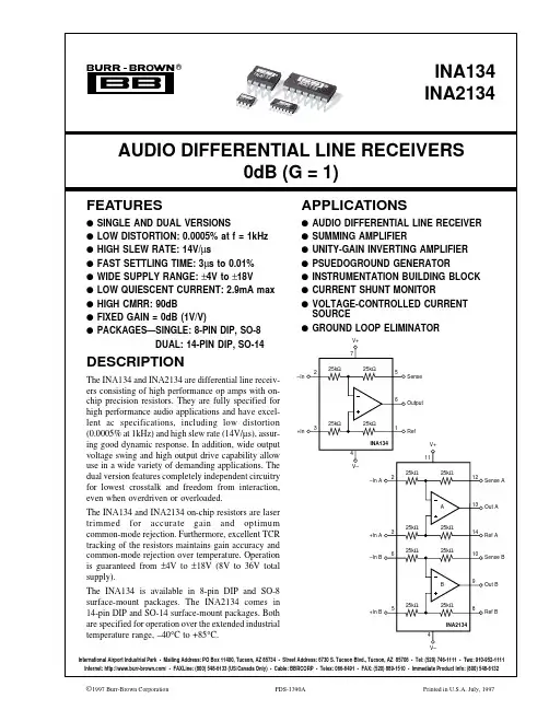
The INA134 and INA2134 are differential line receivers consisting of high performance op amps with onchip precision resistors. They are fully specified for high performance audio applications and have excellent ac specifications, including low distortion (0.0005% at 1kHz) and high slew rate (14V/µs), assuring good dynamic response. In addition, wide output voltage swing and high output drive capability allow use in a wide variety of demanding applications. The dual version features completely independent circuitry for lowest crosstalk and freedom from interaction, even when overdriven or overloaded. The INA134 and INA2134 on-chip resistors are laser trimmed for accurate gain and optimum common-mode rejection. Furthermore, excellent TCR tracking of the resistors maintains gain accuracy and common-mode rejection over temperature. Operation is guaranteed from ±4V to ±18V (8V to 36V total supply). The INA134 is available in 8-pin DIP and SO-8 surface-mount packages. The INA2134 comes in 14-pin DIP and SO-14 surface-mount packages. Both are specified for operation over the extended industrial temperature range, –40°C to +85°C.
®
INA
134 INA 213 4
INA
134
INA
INA134 INA2134
213
4
AUDIO DIFFERENTIAL LINE RECEIVERS 0dB (G = 1)
FEATURES
q SINGLE AND DUAL VERSIONS q LOW DISTORTION: 0.0005% at f = 1kHz q HIGH SLEW RATE: 14V/µs q FAST SETTLING TIME: 3µs to 0.01% q WIDE SUPPLY RANGE: ±4V to ±18V q LOW QUIESCENT CURRENT: 2.9mA max q HIGH CMRR: 90dB q FIXED GAIN = 0dB (1V/V) q PACKAGES—SINGLE: 8-PIN DIP, SO-8 DUAL: 14-PIN DIP, SO-14
Ref B
INA2134 4 V–
International Airport Industrial Park • Mailing Address: PO Box 11400, Tucson, AZ 85734 • Street Address: 6730 S. Tucson Blvd., Tucson, AZ 85706 • Tel: (520) 746-1111 • Twx: 910-952-1111 Internet: / • FAXLine: (800) 548-6133 (US/Canada Only) • Cable: BBRCORP • Telex: 066-6491 • FAX: (520) 889-1510 • Immediate Product Info: (800) 548-6132
–In 2
5
Sense
6
Output
+In
3
25kΩ
25kΩ
1
Ref
V+ 11 25kΩ 25kΩ
INA134 4 V–
–In A 2
12
Sense A
A
13
Out A
+In A
3
25kΩ
25kΩ
14
Ref A
–In B
6
25kΩ
25kΩ
10
Sense B
B
9
Out B
+In B
5
25kΩ
25kΩ
8
VO = –16V to 16V VO = –16V to 16V
±0.1 ±10
±4 IO = 0 –40 –55 –55
±18 ±2.9 85 125 125
100 15 20log (Vrms /0.7746). (2) Includes effects of amplifier’s input current noise and thermal noise contribution of resistor network. (3) Includes effects of amplifier’s input bias and offset currents. (4) 25kΩ resistors are ratio matched but have ±25% absolute value.
®
INA134/2134
2
元器件交易网
PIN CONFIGURATIONS
Top View 8-Pin DIP/SO-8 Top View 14-Pin DIP/SO-14
APPLICATIONS
q AUDIO DIFFERENTIAL LINE RECEIVER q SUMMING AMPLIFIER q UNITY-GAIN INVERTING AMPLIFIER q PSUEDOGROUND GENERATOR q INSTRUMENTATION BUILDING BLOCK q CURRENT SHUNT MONITOR q VOLTAGE-CONTROLLED CURRENT SOURCE q GROUND LOOP ELIMINATOR
% dBu dBu MHz V/µs µs µs µs dB µVrms nV/√HZ µV µV/°C µV/V V V dB kΩ kΩ V/V % ppm/°C % V V mA pF V V mA °C °C °C °C/W °C/W °C/W °C/W
10V Step, CL = 100pF 10V Step, CL = 100pF 50% Overdrive
©1997 Burr-Brown Corporation
PDS-1390A
Printed in U.S.A. July, 1997
SBOS071
元器件交易网
SPECIFICATIONS: VS = ±18V
At TA = +25°C, VS = ±18V, RL = 2kΩ, and Ref Pin connected to Ground, unless otherwise noted. INA134PA, UA INA2134PA, UA PARAMETER AUDIO PERFORMANCE Total Harmonic Distortion + Noise, f = 1kHz Noise Floor(1) Headroom(1) FREQUENCY RESPONSE Small-Signal Bandwidth Slew Rate Settling Time: 0.1% 0.01% Overload Recovery Time Channel Separation (dual), f = 1kHz OUTPUT NOISE VOLTAGE(2) f = 20Hz to 20kHz f = 1kHz OFFSET VOLTAGE(3) Input Offset Voltage vs Temperature vs Power Supply INPUT Common-Mode Voltage Range: Positive Negative Differential Voltage Range Common-Mode Rejection Impedance(4) Differential Common-Mode GAIN Initial Error vs Temperature Nonlinearity OUTPUT Voltage Output, Positive Negative Current Limit, Continuous to Common Capacitive Load (Stable Operation) POWER SUPPLY Rated Voltage Voltage Range Quiescent Current (per Amplifier) TEMPERATURE RANGE Specification Range Operation Range Storage Range Thermal Resistance, θJA 8-Pin DIP SO-8 Surface-Mount 14-Pin DIP SO-14 Surface-Mount VCM = 0V Specified Temperature Range VS = ±4V to ±18V VO = 0V VO = 0V VCM = ±31V, RS = 0Ω 2(V+)–5 2(V–)+5 74 CONDITIONS MIN TYP MAX UNITS
The information provided herein is believed to be reliable; however, BURR-BROWN assumes no responsibility for inaccuracies or omissions. BURR-BROWN assumes no responsibility for the use of this information, and all use of such information shall be entirely at the user’s own risk. Prices and specifications are subject to change without notice. No patent rights or licenses to any of the circuits described herein are implied or granted to any third party. BURR-BROWN does not authorize or warrant any BURR-BROWN product for use in life support devices and/or systems.
V+ 7 25kΩ 25kΩ
DESCRIPTION
The INA134 and INA2134 are differential line receivers consisting of high performance op amps with onchip precision resistors. They are fully specified for high performance audio applications and have excellent ac specifications, including low distortion (0.0005% at 1kHz) and high slew rate (14V/µs), assuring good dynamic response. In addition, wide output voltage swing and high output drive capability allow use in a wide variety of demanding applications. The dual version features completely independent circuitry for lowest crosstalk and freedom from interaction, even when overdriven or overloaded. The INA134 and INA2134 on-chip resistors are laser trimmed for accurate gain and optimum common-mode rejection. Furthermore, excellent TCR tracking of the resistors maintains gain accuracy and common-mode rejection over temperature. Operation is guaranteed from ±4V to ±18V (8V to 36V total supply). The INA134 is available in 8-pin DIP and SO-8 surface-mount packages. The INA2134 comes in 14-pin DIP and SO-14 surface-mount packages. Both are specified for operation over the extended industrial temperature range, –40°C to +85°C.