开关触点配置快速指南
- 格式:pdf
- 大小:347.53 KB
- 文档页数:2


通过速度和简化重新设计测试和测量安全注意事项在使用本产品和任何相关仪器之前,请先阅读以下安全注意事项。
虽然一些仪器和附件通常在无害电压下使用,但是也可能出现对人体有害的情况。
本产品应由能辨别电击危险且熟悉避免潜在伤害的必要安全注意事项的合格人员使用。
使用此产品之前请仔细阅读并遵守所有的安装、操作和维护信息。
有关完整的产品规格,请参阅用户文档。
若以没有指定的方式使用产品,可能丧失产品保修所提供的保障。
产品的用户类型有:责任主体,是负责使用和维护机器,确保在设备规格和运行限制范围内使用设备,并确保操作人员经过充分培训的个人或小组。
操作人员,是负责使用产品特定功能的人员。
他们必须接受过电气安全流程和正确操作仪器方面的培训。
应当采取保护措施,防止他们遭到电击和触碰到危险的带电电路。
维护人员,负责产品日常维护以保持仪器运转正常,例如,设置线路电压或更换耗材。
用户文档中描述了维护步骤。
这些步骤都清楚描述了操作人员是否能够执行它们。
如果不能,那么只能由服务人员来执行这些操作。
服务人员,接受过培训,可操作带电电路,执行安全安装并修理产品。
只有受过正确训练的服务人员才能执行安装和服务流程。
美国吉时利仪器(Keithley Instr uments) 公司的产品专门设计用于测量、控制和数据输入/输出连接等电气信号,而且不能直接连接到电网电压或具有瞬时高电压的电压源上。
Measur ement Categor y II(引自IEC 60664 标准)连接要求针对本地交流电网连接经常发生的高瞬时电压采取保护措施。
某些吉时利测量仪器可以连接到电网上。
这些仪器将会标记为Categor y II 或更高级别。
除非在仪器规格、操作手册和仪器标签中明示允许,否则不要将任何仪器连接到电网上。
存在电击危险时,一定要小心谨慎。
电缆连接器插头或测试装置上可能存在致命电压。
美国国家标准学会(ANSI) 规定,超过30 V RMS、42.4 V峰值或60 VDC 的电压水平存在电击的危险。


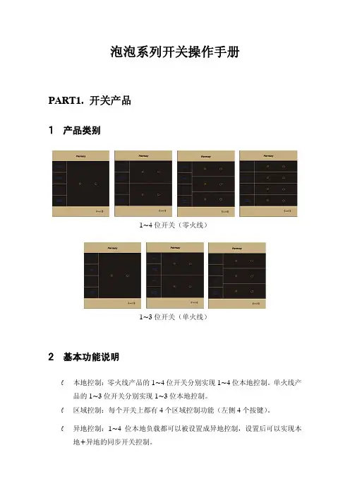
泡泡系列开关操作手册PART1. 开关产品1、产品类别1~4位开关(零火线)1~3位开关(单火线)2、基本功能说明l本地控制:零火线产品的1~4位开关分别实现1~4位本地控制。
单火线产品的1~3位开关分别实现1~3位本地控制。
l区域控制:每个开关上都有4个区域控制功能(左侧4个按键)。
l异地控制:1~4位本地负载都可以被设置成异地控制,设置后可以实现本地+异地的同步开关控制。
l开关设置:实现区域场景设置和异地设置。
l手掌拍全开/全关:当开关所有负载都关闭时,手掌拍开关可以全开所有负载;当开关上有负载打开时,手掌拍开关可以全关所有负载。
l解锁设置。
l区域学习:可以实现区域学习功能。
即所有开关的区域按键设置都与被学习的开关一致。
l复位设置:实现恢复出厂设置。
3、本地控制触摸本地按键,可以实现负载的开关控制。
打开状态:LED灯为蓝色时,负载打开。
此时触摸按键,可以关闭负载。
关闭状态:LED灯为橘红色时,负载关闭。
此时触摸按键,可以打开负载。
4、区域/场景设置方法可以通过网关给开关设置模式。
A方法——所有打开的负载都自动设置进来1)长按被设置的区域按键3秒钟。
2)开关发出嘀嘀2声响,区域的LED不断闪烁。
3)打开所有需要被设置的灯。
4)再按该区域按键,退出设置。
5)如果长按按该区域按键,将进行区域学习设置。
按照A方式设置的区域,控制的时候可以实现对区域内所有设备的全开全关控制。
按照A方式设置的场景,控制的时候可以场景内所有设备的全开。
B方法——可以实现不对称的开关控制1)长按被设置的区域按键3秒钟。
2)开关发出嘀嘀2声响,区域的LED不断闪烁。
3)打开或者关闭需要设置到区域/场景中的设备,并长按其本地按键,3秒后按键LED开始不断闪烁。
4)所有设备设置完毕后,再按该区域按键,退出设置。
5)如果长按按该区域按键,将进行区域学习设置。
6)如果是异地控制,也可以被设置进来。
按照B方式设置的区域,控制的时候可以实现不对称的开关控制,即区域开的时候可以只打开部分设备,区域关的时候关闭所有设备。
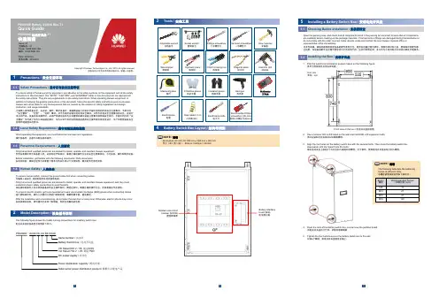
PDU8000 Battery Switch Box-T1Quick GuidePDU8000 电池开关盒-T1快速指南Issue: 01文档版本:01Code :02401606-166编码:02401606-166Date: 2019-8-5发布日期:2019-8-5Copyright © Huawei Technologies Co., Ltd. 2019. All rights reserved .版权所有© 华为技术有限公司2019。
保留一切权利。
The following figure shows the model naming conventions for a battery switch box.电池开关盒的设备型号说明如下所示:1PDU8000–XXXX DC XX BX XXXXBattery Switch box / 电池开关盒V8: Rated 500 V / V8: 额定500V V9: Rated 750 V / V9: 额定750V DC power supply / 直流电Power distribution capacity / 配电容量Serial number / 流水码Data center power distribution product / 数据中心配电产品dimensions (H x W x D): 800 mm x 600 mm x 300 mm 尺寸(高×宽×深):800mm ×600mm ×300mmNOTE / 说明Measuring tape卷尺Adjustable wrench活动扳手Electroprobe电笔Phillips screwdriver 十字螺丝刀Hammer drill 冲击钻Claw hammer 羊角锤Diagonal pliers斜口钳COAX crimping tool压线钳Wire stripper 剥线钳Protective gloves 防护手套Socket wrench 套筒扳手Heat gun 热风枪Electrician's knife电工刀Hydraulic pliers液压钳Insulated gloves 绝缘手套Step ladder (2 m)人字梯(2m)Flat-head screwdriver一字螺丝刀Short-handle Phillips screwdriver (85 mm)短柄十字螺丝刀(85mm)32NOTE / 说明The following table lists the tightening torque of different bolts.各螺栓紧固扭矩说明如下表所示。

100 Mbps PoE Switch Quick Start GuideUD29448B-APrefaceApplicable ModelsThis manual is applicable to 0300P series 100 Mbps PoE switches. Symbol ConventionsThe symbols that may be found in this document are defined as follows.Symbol DescriptionProvides additional information to emphasize or supplement important points of the main text.Indicates a potentially hazardous situation, which if not avoided, could result in equipment damage, data loss, performance degradation, or unexpected results.Indicates a hazard with a high level of risk, which if not avoided, will result in death or serious injury.1 Introduction1.1Product Introduction0300P series 100 Mbps PoE switches are layer 2 PoE switches, providing advanced PoE power supply technology on the basis of high-performance access. The devices support up to 300 m long-range transmission (EXTEND mode), and feature high-priority ports to ensure preferential network transmission in key service areas of users. The devices also support port isolation to guarantee information security, and can enable PoE watchdog to automatically detect and restart ports. The devices are reliable, easy to install and maintain, and equipped with rapid switching functions. With multiple access ports, the devices are suitable for small-scale LAN device access.1.2Packing ListAccessory QuantitySwitch × 1Power Cord × 1L-Shaped Bracket × 2Screw Without Indicator Panel × 4 With Indicator Panel × 6Quick Start Guide × 1Multilingual Information ofNetwork Switch× 11.3AppearanceDevice appearances vary with different models. The actual device prevails.Front Panel0318P series switches (without indicator panels) feature sixteen 10/100 Mbps PoE RJ45 ports, one gigabit RJ45 port, and one gigabit combo port.0318P Series (Without Indicator Panels)0318P series switches (with indicator panels) feature sixteen 10/100 Mbps PoE RJ45 ports and two gigabit combo ports.0318P Series (with Indicator Panels)0326P series switches (without indicator panels) feature twenty-four 10/100 Mbps PoE RJ45 ports, one gigabit RJ45 port, and one gigabit combo port.0326P series switches (with indicator panels) feature twenty-four 10/100 Mbps PoE RJ45 ports and two gigabit combo ports.Note● The front panels of 0326P series switches (without indicator panels) are similar to those of 0318P series switches (without indicator panels). The only difference is that 0326P series switches feature twenty-four 10/100 Mbps PoE RJ45 ports. ● The front panels of 0326P series switches (with indicator panels) are similar to those of 0318P series switches (with indicator panels). The only difference is that 0326P series switches feature twenty-four 10/100 Mbps PoE RJ45 ports, twenty-four portstatus indicators, and twenty-four PoE status indicators.Port/Indicator Description of Front PanelNo.Indicator/PortDescription1 PWR Indicator● Solid on: The switch ispowered on normally.● Unlit: No power supply isconnected or power supply is abnormal.2 PoE-MAX Indicator● Solid on: The output powerof the switch is about to reach or has reached the upper limit. The power supply may be abnormal if more devices are connected.● Unlit: The switch does notsupply power to a powered device (PD), or the switch supplies power to a PD normally and the output power of the switch does not reach the upper limit.NoteThe PoE-MAX indicator will be unlit in five seconds after the output power of the switch reaches the upper limit.3Gigabit RJ45 Port Indicator (when gigabit RJ45 port G1 is connected) ● Solid on: The port isconnected.● Flashing: The port istransmitting data. ● Unlit: The port isdisconnected or connection is abnormal.Gigabit SFP Fiber Optical Port Indicator (when gigabit SFP fiber optical port G1-F is connected)● Solid on: The gigabit SFPfiber optical port is connected.● Flashing: The gigabit SFPfiber optical port is transmitting data.● Unlit: The gigabit SFP fiberoptical port is disconnected or connection is abnormal.4 Gigabit RJ45 PortIndicator (when thedevices featureonly one comboport G1/G1-F orwhen gigabit RJ45port G2 isconnected)●Solid on: The port isconnected.●Flashing: The port istransmitting data.●Unlit: The port isdisconnected or connectionis abnormal.Gigabit SFP FiberOptical PortIndicator (whengigabit SFP fiberoptical port G2-F isconnected)●Solid on: The gigabit SFPfiber optical port isconnected.●Flashing: The gigabit SFPfiber optical port istransmitting data.●Unlit: The gigabit SFP fiberoptical port is disconnectedor connection is abnormal.5 LINK/ACT Indicator(for switcheswithout indicatorpanels)●Solid on: The port isconnected.●Flashing: The port istransmitting data.●Unlit: The port isdisconnected or connectionis abnormal.10/100 Mbps RJ45Port Indicator (forswitches withindicator panels)6 PoE Indicator (forswitches withoutindicator panels) ●Solid on: The switchsupplies power to a PDnormally.●Unlit: The switch isdisconnected from a PD orpower supply is abnormal. PoE Status Indicatorof 10/100 MbpsRJ45 Port (forswitches withindicator panels)7 EXTEND DIP Switch Enable or disable long-range transmission (EXTEND mode).●When the DIP switch is setto “ON”, the correspondingports support up to 300 mnetwork transmission witha port rate of 10 Mbps.●When the DIP switch is setto “OFF”, the correspondingports support up to 100 mnetwork transmission witha port rate of 100 Mbps.8 Isolation DIP Switch Enable or disable port isolation.●When the DIP switch is setto “ON”, port isolation isenabled. Ports in the sameisolation group cannotcommunicate with eachother. Data transmission viaeach port is isolated toenhance network security.Note● Ports 1 to 8 of 0318P and 0326P series switches are high-priority ports used to prioritize network transmission in keyservice areas.●When the DIP switch isswitched to “OFF”, port isolation is disabled. Ports can communicate with each other.9PoE Watchdog DIP SwitchEnable or disable PoE watchdog.● When the DIP switch is setto “ON”, PoE watchdog is enabled to automatically detect device connection statuses of corresponding ports and restart ports in case of communication failures.● When the DIP switch is setto “OFF”, PoE watchdog is disabled. Corresponding ports are no longer automatically detected and restarted in case of communication failures.1010/100 Mbps PoE RJ45 PortUsed for connection to a PD via a network cable.11Gigabit Combo Port (G1/G1-F)When connected to a network cable, the combo port is a RJ45 port. When plugged into with an optical module and connected to an optical fiber, the combo port functions as a fiber optical port.Note● A combo port consists of aRJ45 port and a fiber optical port. You can use either the RJ45 port or the fiber optical port of a combo port, but cannot use them at the same time. For example, if RJ45 port G1 is connected, fiber optical port G1-F is unavailable. ● When connected to both anetwork cable and an optical fiber, the combo port works as a fiber optical port.12Gigabit Combo Port (G2/G2-F) Gigabit RJ45 Port (G2) (when the devices feature only one combo port G1/G1-F)Used for connection to another device via a network cable.● Ports supporting long-range transmission vary with devicemodels. Ports 9 to 16 of 0318P series switches and ports 17 to 24 of 0326P series switches support up to 300 m network transmission.● Ports supporting port isolation vary with device models. Ports1 to 16 of 0318P series switches and ports 1 to 24 of 0326P series switches support port isolation.● Ports supporting PoE watchdog vary with device models. Ports1 to 16 of 0318P series switches and ports 1 to 24 of 0326P series switches support PoE watchdog.Rear Panel0318P/0326P Series (Without Indicator Panels)0318P/0326P Series (with Indicator Panels)Port/Indicator Description of Rear PanelNo.Indicator/Port Description1 Grounding Terminal Used for connecting to the grounding cable to protect the switch from lightning.2Power SupplyUse the attached power cord to connect the switch to a socket.2 InstallationPlease select the appropriate installation method according to the actual needs.NoteIf screws are not provided in the package, prepare them yourself. Before You Start● Ensure that the desktop, wall, rack, or rail is stable and firmenough.● Keep the room well-ventilated. Leave at least 10 cm of heatdissipation space around the device.● Keep at least 1.5 cm vertical distance between two adjacent devices for rack-mounted installation.2.1 Desktop InstallationPlace the device on the desk.2.2 Wall-Mounted InstallationSteps1. Check the distance between the two hanging holes on the rear cover of the device.2. Insert two M4 screws into the wall.●Ensure that the distance between the two screws equals to the distance between the two hanging holes.●Set aside at least 4 mm of the screw bodies outside the wall.3.Align the hanging holes with the screws, and hang the device on the screws.Wall-Mounted Installation2.3Rack-Mounted InstallationSteps1.Check the grounding and stability of the rack.e screws to fix the two L-shaped brackets to both sides of the device.Fix L-Shaped Brackets3.Place your device against the rack, and fix the brackets to the rack with screws to stably install your device.Fix Brackets to Rack3 Grounding3.1Connect Grounding CableGrounding is used to quickly release overvoltage and overcurrent induced by lightening on the device, and to protect personal safety. Select an appropriate grounding method according to the installation conditions.The grounding terminal is on the rear panel or side panel of the device. The actual device prevails.3.1.1With Grounding BarIf a grounding bar is available at the installation site, follow the steps below.Steps1.Connect one end of the grounding cable to the binding post on the grounding bar.2.Connect the other end of the grounding cable to the grounding terminal of the device and tighten the screw.Grounding with Grounding Bar3.1.2Without Grounding BarIf there is no grounding bar but the earth is nearby and the grounding body is allowed to be buried, follow the steps below. Steps1.Bury an angle steel or steel pipe (≥ 0.5 m) into the earth.2.Weld one end of the grounding cable to the angle steel or steel pipe and embalm the welding point via electroplating or coating.3.Connect the other end of the grounding cable to the grounding terminal.Grounding with Angle Steel3.2Connect RJ45 PortUse a network cable to connect the device to the RJ45 port of a peer device such as network camera, NVR, switch, etc.RJ45 Port Connection3.3Connect SFP Optical ModuleConnecting an SFP optical module is supported when the device has a fiber optical port or a combo port.Steps●Single-Mode optical module needs to be paired for use.●Do not bend an optical fiber (curvature radius ≥ 10 cm) overly.●Do not look directly at an optical fiber connector because thelaser generated is harmful to eyes.1.Connect the two paired SFP optical modules with an optical fiber.2.Hold the SFP optical module from one side, and smoothly plug it into the device along the SFP port slot until the optical module and the device are closely attached.3.After powering on the device, check the status of the optical port indicator.-If the indicator is lit, the link is connected.-If the indicator is unlit, the link is disconnected.4.Check the line, and make sure that the peer device has been enabled.4 Device Powering-OnPlease use the attached power adapter or power cord to power on the device.Before powering on your device, make sure that:•The operating power supply is compliant with rated input standard.•Port cables and grounding cables are correctly connected.•If there is outdoor cabling, connect a lightning rod and alightening arrester to the cable.Power supply lines and strong current wires cannot be wiredtogether, otherwise PDs or switch ports will be burnt.。

华为路由TC7102快速入门认识路由器WAN/LAN 自适应接口:连接天翼网关、电脑等发现可配对的 HUAWEI HiLink 智能设备,路由器指示灯自动变为慢闪。
此时点按一下路由器的 H 键后,指示灯闪烁加快,可配对设备将连接路由器的Wi-Fi。
连上后,路由器指示灯停止闪烁。
请参考本手册,配置路由器。
请确保网线无松动和连接无错误。
请致电中国电信,确认网络是否存在故障。
红色常亮绿色常亮可以上网闪烁HiLink 模式下,路由器已检测到可配对的设备:无法上网:指示灯若您误碰 H 键导致指示灯闪烁,请等待2分钟,指示灯会自动恢复。
路由器的 H 键同时具有 WPS 按键功能。
连线路由器四根天线均竖直向上,Wi-Fi 信号更优。
设置上网路由器的指示灯绿色常亮表示可以上网。
路由器的 Wi-Fi 名称和密码自动与天翼网关相同。
无需配置,即插即用。
若不确定您的天翼网关是否支持 e-Link 智能组网,请联系中国电信(服务热线:10000)。
情景一:您的天翼网关支持 e-Link 智能组网123手机连接路由器 Wi-Fi ,Wi-Fi 名称和密码请查看路由器底部。
输入宽带账号和密码。
若您只有一根网线,可以先用这根网线连接旧路由器获取网络配置,获取成功后,再用这根网线连接新路由器的任意网口和上行网络(如:天翼网关)。
您也可以用网线将电脑连接到路由器,使用电脑设置上网。
界面请以实际产品为准。
打开浏览器,页面自动跳转(若未跳转,请输入“192.168.2.1”),输入登录密码,登录密码请查看路由器底部。
若您记得宽带帐号和密码,请直接输入。
若您忘记了宽带帐号和密码,请选择从旧路由器获取:另取一根网线连接旧路由 WAN 口和新路由器的任意网口。
输入或联系中国电信,获取宽带帐号和密码。
连接好路由器的电源线和网线后,请参照以下步骤设置上网。
情景二:您的天翼网关不支持 e-Link 智能组网设置路由器的新 Wi-Fi 和管理密码。

快速安装指南00825-0106-4030, Rev GB2022 年 3 月Rosemount™ 2120 液位开关振动音叉快速安装指南2022 年 3 月内容关于本指南 (3)安装 (5)准备电气连接件 (11)接线和通电 (26)组态 (30)操作 (32)2Rosemount 2120 液位开关2022 年 3 月快速安装指南1关于本指南本快速安装指南提供 Rosemount2120的基本安装指导。
更多说明,请参阅Rosemount 2120参考手册。
手册和本指南的电子版本亦可以从/Rosemount获得。
1.1安全信息警告不遵守安全安装与检修准则,可能导致死亡或严重受伤。
请确保由取得相关资质人员按照相应的操作规程安装物位开关。
只能使用本手册中规定的物位开关。
只能使用本手册中规定的物位开关。
带重型法兰和延长型音叉的物位开关的重量可能超过 37 lb. (18 kg)。
搬运、吊装和安装物位开关前必须执行风险评估。
修理设备(例如更换组件等)可能危害安全性,在任何情况下都是不允许的。
警告爆炸可能会导致死亡或严重受伤。
验证物位开关的工作环境符合相应的危险场所认证。
在易爆气体环境中,连接手持通讯器之前,请确保按照本质安全或非易燃现场接线实践安装仪表。
在隔爆以及非易燃型安装中,不得在液位开关通电的情况下拆卸壳体盖子。
为满足隔爆要求,壳体盖子必须完全盖上。
警告触电可能导致死亡或严重受伤。
不得接触引线或接线端子。
引线上可能存在的高压会导致触电。
在进行物位开关接线时,请确保物位开关的电源处于关闭状态,并且与任何其他外部电源连接的线路均处于断开状态,或者没有通电。
确保接线符合电流要求,且绝缘符合电压、温度和环境要求。
快速安装指南3快速安装指南2022 年 3 月警告过程泄漏可能导致死亡或严重受伤。
请务必轻拿轻放物位开关。
如果过程密封件受损,气体可能会从容器(储罐)或管道中逸出。
警告物理接触未经授权的人员可能会对最终用户的设备造成明显受损和/或误组态。

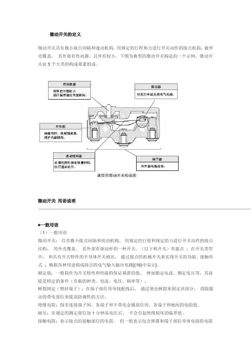
微动开关的定义微动开关具有微小接点间隔和速动机构,用规定的行程和力进行开关动作的接点机构,被外壳覆盖,其外部有传动器,且外形较小。
下图为典型的微动开关构造的一个示例。
微动开关由5个大类的构成要素组成。
微动开关用语说明■一般用语(1)一般用语微动开关:具有微小接点间隔和快动机构,用规定的行程和规定的力进行开关动作的接点结构,用外壳覆盖,其外部有驱动杆的一种开关。
(以下称开关)有接点:在开关类型中,和具有开关特性的半导体开关相比,通过接点的机械开关来实现开关的功能。
接触形式:根据各种用途构成接点的电气输入输出电路[(16)中显示]。
额定值:一般指作为开关特性和性能的保证基准的值,例如额定电流、额定电压等,其前提是特定的条件(负载的种类、电流、电压、频率等)。
树脂固定(塑封端子):在端子部位用导线配线后,通过填充树脂来固定该部分,消除露出的带电部位来提高防滴性的方法。
绝缘电阻:指非连接端子间、各端子和不带电金属部位间、各端子和地间的电阻值。
耐压:在规定的测定部位加1分钟高电压后,不会引起绝缘损坏的临界值。
接触电阻:表示接点的接触部位的电阻,但一般表示包含弹簧和端子部位导体电阻的电阻值。
抗振性:误动作振动微动开关在使用时,由于振动闭合的接点在超过规定的时间内不分离的振动范围。
抗冲击性:耐久冲击指微动开关在运输中或者安装时不会受到由该机械冲击带来的各部位的损伤,并满足动作特性的范围内的冲击。
误动作冲击?指微动开关使用时由于冲击闭合的接点在超过规定的时间内不分离的冲击范围。
(2)关于结构、构造的用语●微动开关的结构、构造(3)有关寿命的用语机械寿命:指接点不通电,以规定的操作频率将过行程(OT)设定为规格值使其运行时的开关寿命。
电气寿命:在接点上连接额定负载,以规定的操作频率将过行程(OT)设定为规格值进行开关时的开关寿命。
(4)标准试验状态开关的试验条件如下。
环境温度:20±2℃、相对湿度:65±5%RH、气压:101.3kPa(5)N水平参考值表示可靠度为60%(λ60)下的故障水平。
文档版本:04发布日期:2016-01-08SCC800-B1 连接华为开关电源 快速指南版权所有 © 华为技术有限公司2016。
保留一切权利。
华为开关电源EPMU01 (场景一)SCC800-B1 COM 口PIN 脚 华为开关电源RS232/RS422口PIN 脚 1白(橙) 1白(橙) 2橙 2橙 4蓝 4蓝 5白(蓝)5白(蓝)华为开关电源EPMU01 (场景二)SCC800-B1 COM 口PIN 脚 华为开关电源RS232/RS422口PIN 脚1白(橙)1白(橙)2橙 2橙 4蓝 4蓝 5白(蓝)5白(蓝)网线的有效信号线是1、2、4、5四根,为了避免引起干扰,其他引脚不接线。
网线的有效信号线是1、2、4、5四根,为了避免引起干扰,其他引脚不接线。
网线的有效信号线是1、2、4、5四根,为了避免引起干扰,其他引脚不接线。
SCC800-B1 COM口PIN脚华为开关电源COM_IN口PIN脚1白(橙)1白(橙)2橙2橙4蓝4蓝5白(蓝)5白(蓝)接线方案(插框SMU06C )接线方案(门装SMU06C )监控模块的LCD 界面上进入“参数设置”菜单时,需要输入登录密码,预设密码为“000001” 。
参数配置线缆连接完毕后,需要在华为开关电源监控模块的LCD 界面上,配置如下参数:1、将“端口模式”设置为“手动”,将“通信协议类型”设置为“电总协议”。
LCD 路径:主菜单 > 参数设置 > 通信参数 > 端口设置 > 北向485通信端口2、将“通信地址”设置为“1”,“波特率”设置为“9600”。
LCD 路径:主菜单 > 参数设置 > 通信参数 > 电总协议 网线的有效信号线是1、2、4、5四根,为了避免引起干扰,其他引脚不接线。
网线的有效信号线是1、2、4、5四根,为了避免引起干扰,其他引脚不接线。
SCC800-B1 COM 口PIN 脚华为开关电源RS485/RS232口PIN 脚1白(橙) 1白(橙)2橙 2橙 4蓝 4蓝 5白(蓝)5白(蓝)SCC800-B1 COM 口PIN 脚 华为开关电源RS485/RS232口PIN 脚1白(橙) 1白(橙)2橙 2橙 4蓝 4蓝 5白(蓝)5白(蓝)华为开关电源SMU02B ( V3xxRxxxCxx 版本或者V5xxRxxxCxx 版本)接线方案SCC800-B1 COM 口PIN 脚华为开关电源RJ45口PIN 脚1白(橙) 1白(橙)2橙 2橙 4蓝 4蓝 5白(蓝)5白(蓝)网线的有效信号线是1、2、4、5四根,为了避免引起干扰,其他引脚不接线。
110 SERIES UNMANAGED+ NETWORK SWITCHESQuick Start GuideAN-110-SW-C-5AN-110-SW-F/R-8AN-110-SW-F/R-16AN-110-SW-F/R-242Araknis Networks 110 Series Unmanaged+ Network Switches Quick Start GuideFCC WarningChanges or modifications not expressly approved by the party responsible for compliance could void the user’s authority to operate the equipment. This device complies with Part 15 of the FCC Rules. Operation is subject to the following two conditions: This device may not cause harmful interference, andThis device must accept any interference received, including interference that may cause undesired operation.NOTE: This equipment has been tested and found to comply with the limits for a Class A digital device, pursuant to part 15 of the FCC Rules. These limits are designed to provide reasonable protection against harmful interference when the equipment is operated in a commercial environment. This equipment generates, uses, and can radiate radio frequency energy and, if not installed and used in accordance with the instruction manual, may cause harmful interference to radio communications. Operations of this equipment in a residential area is likely to cause harmful interference in which case the user will be required to correct the interference at his own expense.123Araknis Networks 110 Series Unmanaged+ Network SwitchesQuick Start Guide© 2016 Araknis Networks®CE WarningThis is a Class A product. In a domestic environment, this product may cause radio interference, in which case the user may be required to take adequate measures.UL StatementAll models have been evaluated by UL.This device is intended for indoor use only. It should not be connected to an Ethernet network with outside plant routing.Araknis Networks 110 Series Unmanaged+ Network SwitchesQuick Start GuideWelcome to Araknis Networks™Thank you for choosing an Araknis 110-series Network Switch. With Gigabit connectivity on all ports, updated modern aesthetics, and a level of control (unmanaged+) rarely seen in unmanaged solutions, the Araknis 110-series switch is a sleek and highly capable addition to any network.45Araknis Networks 110 Series Unmanaged+ Network SwitchesQuick Start Guide© 2016 Araknis Networks®Step 1: UnboxSwitch (1)DC Power Supply(AN-110-SW-C-5 only)Quick Start GuideRubber Feet for FlatSurfaces (4)8, 16, 24 Models Rack-Mount Kit:Ears (2), Screws (8)AN-110-SW-C-5Wall-Mount Kit:Ears (2)Ear Screws (4)Black Wood Screws (2)Silver Ball Screws (2)AC Power Cord(8/16/24 port models)7Araknis Networks 110 Series Unmanaged+ Network SwitchesQuick Start Guide© 2016 Araknis Networks®AN-110-SW-C-5Wall MountShelf MountAraknis Networks 110 Series Unmanaged+ Network SwitchesQuick Start GuideStep 3: ConnectComputerNOTE: AN-110-SW-R-8 shown. Connection is the same for models with both front- and rear-facing ports. 89Araknis Networks 110 Series Unmanaged+ Network SwitchesQuick Start Guide© 2016 Araknis Networks®Step 4: VerifyPower LED –O n: system is up. Off: system is down.1Gbps LED – O n: port connected at 1000Mbps speed. Off: port is connected at 10/100Mbps speed.Link/Act LED – O n: port is connected to another device.Blinking: packets are running through the port. Off: port is not connected to a device.AN-110-SW-R-8AN-110-SW-F-810Araknis Networks 110 Series Unmanaged+ Network Switches Quick Start GuideOther Access Methods: OvrCWeb BrowserMobileOvrC provides remote firmware upgrades, real-time notifications, and intuitive customer management, right from your computer or mobile device. Setup is plug-and-play, with no port forwarding or DDNS address required. T o add this device to your OvrC account:Connect the switch to the network (Internet access required).Log Into OvrC () or load the OvrC app.Add the device (MAC address and Service T ag numbers needed for authentication).11Araknis Networks 110 Series Unmanaged+ Network SwitchesQuick Start Guide © 2016 Araknis Networks®Reboot – P ress and hold the RESET button on the back of theswitch for 5 seconds, then release. The switch will powercycle and the front status lights will flash.Factory Reset – P ress and hold the RESET button for 10-15 seconds untilthe status LEDs flash once. The switch will power cycleand be reset to factory default settings.Pro Tip: Rebooting the SwitchAN-110-SW-R-8AN-110-SW-F-8© 2016 Araknis Networks® 160727-10202-Y ear Limited WarrantyAraknis Networks® products have a 2-Y ear Limited Warranty. This warranty includes parts and labor repairs on all components found to be defective in material or workmanship under normal conditions of use. This warranty shall not apply to products that have been abused, modified, or disassembled. Products to be repaired under this warranty must be returned to a designated service center with prior notification and an assigned return authorization (RA) number. Contact technical support for an RA number.Contact InformationT echnical Support (866) 838-5052。
Agilent Technologies系统直流电源N5700 系列快速参考指南A安全注意事项在操作本仪器的所有阶段,必须遵守下列一般性安全预防措施。
不遵守这些预防措施或本手册中的其他特定警告或说明,将违反该仪器的设计、制造和使用的安全标准。
安捷伦科技公司对客户不遵守这些规定而导致的后果不承担任何责任。
一般原则不要以制造商规定之外的方式使用本产品。
如不按照操作手册中规定的方式使用本产品,其保护功能可能会失效。
接通电源前检查是否已采取所有安全预防措施。
在接通电源前,确保进行了设备的所有连接。
请留意在“安全符号”下面介绍的仪器外部标识。
将仪器接地本产品为 1 类安全仪器(提供了保护接地端子)。
要将电击危险降到最低程度,必须将仪器机箱和机盖接地。
必须通过接地电源线将仪器连接到交流电源,接地电线要牢固地连接到电源插座的电气接地(安全接地)端。
中断保护(接地)导线或断开保护接地端子,将产生可导致人身伤害的潜在电击危险。
熔断器为避免火灾,请仅使用指定型号和额定值(正常熔断、延时等)的熔断器来更换电源熔断器。
不要使用维修过的熔断器或短路的熔断器座。
否则可能引起电击或火灾。
不要在易爆环境中操作不要在有易燃性气体或烟雾的场所使用本仪器。
不要卸下仪器机盖只能由合格的、经过维修培训且了解潜在危险的专业人员打开仪器机盖。
在卸下仪器机盖之前,要断开电源线和外部电路。
不要改动仪器不要安装代用零件或对产品擅自改动。
请将仪器返回安捷伦销售和服务部进行维护和维修,以保持其安全特性。
发生损坏时仪器一旦出现损坏或故障迹象,应停止操作并防止无意操作,并等待合格的维修人员进行修理。
小心符号表示存在危险。
它提请用户对某一操作过程、操作方法或类似情况的注意。
如果不能正确执行或遵守规则,则可能对产品造成损坏或丢失重要数据。
在完全理解和满足所指出的小心条件之前,不要继续下一步。
警告符号表示存在危险。
它提请用户对某一操作过程、操作方法或类似情况的注意。
开关触点配置快速指南
无论是寻找按钮、微型开关、摇臂开关、旋转开关还是拨动开关,最好记住基本的开关配置。
开关必须至少具有两片称为触点的导电材料。
触点连接至外电路,基本操作是接通触点或断开触点,使电路打开或关闭。
接通即打开电路,断开即关闭电路。
不同开关的配置可能有所不同,这取决于刀和掷的数量。
刀为触点组的数量,而掷为传导位的数量。
刀和掷
常见配置:
∙单极单掷,缩写为SPST
∙双极单掷,缩写为DPST
∙单极双掷,缩写为SPDT
∙双极双掷,缩写为DPDT
简要概述和常见图解
SPST –简单的双控开关,开关内仅有一条电路和一个接通位置。
DPST –开关内可同时操作两条电路,同时切换两条开关电路,还可用于隔离带电电路和中性电路。
SPDT –用于在两个位置接通,在独立电路之间切换。
L1可为警示灯,L2可为发声器。
该配置又称为转接开关,因配备第三个切换位置,还可以中间位置断开。
DPDT –有两个瞬动开关同时操作,同时切换两个装置,例如警示灯和发声器,相当于两个SPDT开关。
具有中间位置断开的DPDT可用于电机控制,使用正转反转操作。