NI SystemLink远程测试、测量系统管理平台简介
- 格式:pptx
- 大小:15.41 MB
- 文档页数:40

美国国家仪器公司推出用于分布式系统管理的应用软
件SystemLink
2018年5月8日- NI (美国国家仪器公司,National Instruments,简称NI) 以软件为中心的平台供应商,助力于加速自动化测试和自动化测量系统的开发进程和性能提升,宣布推出用于分布式系统管理的应用软件SystemLink。
SystemLink为软件部署、远程设备配置和系统健康性能监控等自动化任务提供了一个集中界面,有助于提高运营效率并降低维护成本。
工业物联网、5G和车辆电气化等趋势,加上需要维护分布式传统系统等当前需求,激励着企业寻求新的系统管理方法。
集中调控的网联系统已经从理论和试点项目发展为大规模的分布式部署,并带来了可观的业务回报。
这些回报来自于从数据提取的可付诸实践的信息,这些信息帮助他们最大限度地延长正常运行时间,提高效率并推动未来的产品创新。
与此同时,企业需要在采用新的互联技术与继续支持长寿命周期的重要遗留资产之间取得平衡。
无论是小规模试点项目还是大规模系统群,管理、维护以及提取信息的系统实现起来都相对简单。
而人们的关注点现在转向下一个挑战:即扩展和管理大型部署、不断变化的生命周期阶段以及整个工厂和站点的分布式测试设备和节点。
这一挑战涉及远程软件和系统配置以及数据管理和性能监控等任务,并适用于国防和航空航天、运输和制造等行业。
基于LabVIEW的实验室仪器远程控制管理系统在当今科技迅速发展的时代,实验室仪器的管理和控制方式也在不断地革新。
基于 LabVIEW 的实验室仪器远程控制管理系统应运而生,为实验室的高效运作和科学研究提供了有力的支持。
LabVIEW 是一种图形化编程环境,它具有强大的数据采集、分析和控制功能。
利用 LabVIEW 开发实验室仪器远程控制管理系统,能够实现对仪器的远程操作、实时监测、数据记录和分析等一系列功能,极大地提高了实验效率和数据准确性。
一、系统的需求分析首先,实验室仪器远程控制管理系统需要满足不同类型仪器的接入需求。
实验室中的仪器种类繁多,包括电子测量仪器、分析仪器、物理实验仪器等,每种仪器都有其独特的通信协议和控制方式。
因此,系统需要具备良好的兼容性,能够与各种仪器进行通信和交互。
其次,系统应具备可靠的远程控制功能。
操作人员可以通过网络在异地对实验室仪器进行启动、停止、参数设置等操作,并且能够实时获取仪器的工作状态和反馈信息。
这不仅方便了实验人员的工作,还能够在紧急情况下及时停止实验,保障人员和设备的安全。
此外,数据采集和处理也是系统的重要需求之一。
系统需要能够准确地采集仪器产生的数据,并进行实时处理和分析,为实验研究提供有价值的信息。
同时,数据的存储和管理也至关重要,以便后续的查询和回溯。
二、系统的总体架构基于 LabVIEW 的实验室仪器远程控制管理系统通常由仪器端、服务器端和客户端三部分组成。
仪器端负责与实际的实验室仪器进行连接和通信,采集仪器的工作数据和状态信息,并将其上传至服务器端。
为了实现与不同仪器的通信,通常需要使用各种通信接口和协议转换模块。
服务器端是系统的核心部分,负责接收和处理来自仪器端的数据,同时响应客户端的请求。
服务器端需要具备强大的数据处理能力和存储能力,以保证系统的稳定运行和数据的安全性。
客户端则是提供给用户的操作界面,用户可以通过客户端远程访问服务器,实现对实验室仪器的控制和管理。
Architectures for Implementing a Hardware-in-the-Loop SystemOverviewYou can test embedded control systems more efficiently with the powerful method of hardware-in-the-loop (HIL) simulation. Safety, availability, or cost considerations can make it impractical to perform all the necessary tests with the complete embedded control system. Using HIL simulation, you can simulate the parts of the system that pose these challenges. By thoroughly testing the embedded control device in a virtual environment before proceeding to real-world tests of the complete system, you can maintain reliability and time-to-market requirements in a cost-effective manner even as the systems you are testing become more complex.ContentsComponents of an HIL Test System (2)Hardware Fault Insertion (2)Testing Multi-ECU Systems (2)Additional Processing Power—Distributed Processing (3)Simplified Wiring—Distributed I/O (4)Implementing HIL Test Systems (4)Next Steps (5)Components of an HIL Test SystemAn HIL test system consists of three primary components: a real-time processor, I/O interfaces, and an operator interface. The real-time processor is the core of the HIL test system. It provides deterministic execution of most of the HIL test system components such as hardware I/O communication, data logging, stimulus generation, and model execution. A real-time system is typically necessary to provide an accurate simulation of the parts of the system that are not physically present as part of the test.The I/O interfaces are analog, digital, and bus signals that interact with the unit under test. You can use them to produce stimulus signals, acquire data for logging and analysis, and provide the sensor/actuator interactions between the electronic control unit (ECU) being tested and the virtual environment being simulated by the model. The operator interface communicates with the real-time processor to provide test commands and visualization. Often, this component also provides configuration management, test automation, analysis, and reporting tasks.Figure 1. An HIL test system consists of three primary components: an operator interface, a real-timeprocessor, and I/O interfaces.Hardware Fault InsertionMany HIL test systems use hardware fault insertion to create signal faults between the ECU and the rest of the system to test, characterize, or validate the behavior of the device under these conditions. To accomplish this, you can insert fault insertion units (FIUs) between the I/O interfaces and the ECU to allow the HIL test system to switch the interface signals between normal operation and fault conditions such as a short-to-ground or open circuit.Figure 2. You can use hardware fault insertion to test the behavior of the ECU during signal faults. Testing Multi-ECU SystemsSome embedded control systems, such as an automobile, aircraft, or wind farm, use multiple ECUs that are often networked together to function cohesively. Although each of these ECUs may initially be testedindependently, a system’s integration HIL test sys tem, such as a full vehicle simulator or iron bird simulator, is often used to provide more complete virtual testing. When testing a multi-ECU control system (and even some single ECU control systems), two needs often arise: additional processing power and simplified wiring.Figure 3. Automobiles, aircraft, and wind farms use multiple ECUs. Additional Processing Power—Distributed ProcessingEven with the latest multicore processing power, some systems require more processing power than what is available in a single chassis. To address this challenge, you can use distributed processing techniques to meet the performance requirements of these systems. In very high-channel-count systems, the need is more than simply additional processing power, additional I/O is also necessary. In contrast, systems using large, processor-hungry models often use additional chassis only for the extra processing power, allowing those processors to remain dedicated to a single task for greater efficiency. Depending on how the simulator tasks are distributed, it may be necessary to provide shared trigger and timing signals between the chassis as well as deterministic data mirroring to allow them to operate cohesively.Figure 4. When using multiple chassis for additional processing power, it is often necessary to provide timing and data synchronization interfaces between them.Simplified Wiring—Distributed I/OImplementing and maintaining wiring for high-channel-count systems can pose costly and time-consuming challenges. These systems can require hundreds to thousands of signals be connected between the ECU and the HIL test system, often spanning many meters to compensate for space requirements.Fortunately, deterministic distributed I/O technologies can help you tame these wiring complexities and provide modular connectivity to ECUs, which allows for efficient system configuration modifications. Instead of routing all connections back to a single rack containing one or more real-time processing chassis instrumented with I/O interfaces, you can use deterministic distributed I/O to provide modular I/O interfaces located in close proximity to each ECU without sacrificing the high-speed determinism necessary for accurate simulation of the virtual parts of the system.This approach greatly reduces HIL test system wiring cost and complexity by making it possible for the connections between the ECU and the I/O interfaces to be made locally (spanning less than a meter) while a single bus cable is used to span the additional distance to the real-time processing chassis. Additionally, with the modular nature of this approach, HIL test systems can easily scale, incrementally, from a multi-ECU test system in which all but one of the ECUs are simulated to a complete system integration HIL test system where none of the ECUs are simulated.Figure 5. Deterministic distributed I/O interfaces greatly reduce HIL test system wiring cost and complexity because the connections between the ECU and the I/O interfaces can be made locally. Implementing HIL Test SystemsAfter you have selected the appropriate architecture for your HIL test system, the first step in creating a HIL test system is to select the components that best meet your development requirements. NI provides a wide variety of real-time processing and I/O options for implementing HIL test systems. Because they are all based on open industry standards, you can be assured that they always deliver the latest advances in PC technology to your HIL test system and always meet future test system requirements.The NI HIL platform is open and extensible, which means that it can adapt to changing system requirements. Because of its modular architecture, the NI HIL platform can be easily upgraded with additional functionality, which helps you future proof your test systems and meet the requirements of the most demanding embedded software testing applications. In addition to the widest range of I/O on market, NI offers software tools that help you automate your HIL tests, perform post-processing and report generation, and map test results to requirements. These tools help you perform a wider range of tests earlier in the software development process, which reduces overall development cost while improving product quality.。

基于NI实时控制器的六自由度平台测控系统设计与实现王效亮;张芳;曾宪科;栾婷;陈成峰【摘要】六自由度平台测控系统是六自由度平台的电气控制部分,它通过对六路液压缸的实时闭环控制,实现对平台位姿的控制;该测控系统采用NI的计算机,配置多种类型的PXI板卡,实现了对平台的电压、电流、数字IO、CAN总线等多种接口类型的测量和控制,满足了可靠性需求;采用了典型的上下位机控制,分别进行实时计算与任务管理,解决了实时性的控制需求;采用NI的虚拟仪器Labview开发测控软件,完成实时计算平台的正解与反解模块,作动器闭环控制等功能,增强系统的功能和灵活性;目前六自由度平台测控系统的硬件部分和软件部分都已经通过了调试,对系统进行了正弦运动和暂态特性测试,实验结果表明,运行速度快,满足了平台的控制要求.【期刊名称】《计算机测量与控制》【年(卷),期】2019(027)002【总页数】6页(P24-28,33)【关键词】六自由度平台;软件;SIT仿真模型【作者】王效亮;张芳;曾宪科;栾婷;陈成峰【作者单位】北京精密机电控制设备研究所,北京 100081;北京精密机电控制设备研究所,北京 100081;北京精密机电控制设备研究所,北京 100081;北京精密机电控制设备研究所,北京 100081;北京精密机电控制设备研究所,北京 100081【正文语种】中文【中图分类】TP273+.50 引言六自由度平台是一种模拟航天器空间运动姿态的模拟器,在其行程范围内可以模拟任意空间运动。
六自由度是平台具有六个自由运动的维度,即纵向、升降、横向、俯仰、横滚、偏航[1]。
通过对6个液压作动器的精确控制和解藕算法,实现对平台的6个自由度的位姿控制。
其系统示意图如图1所示。
图1 六自由度平台示意图六自由度运动平台可以实现对既定的轨迹的跟踪,作为运动仿真平台有着广泛的应用:1)可以作为航空飞行模拟器;2)可以作为机器人的模拟运动机构;3)在娱乐界可以作为体感模拟娱乐机;4)用作飞机、船舶、潜艇、航天器等运动载体中相关仪器设备的试验。
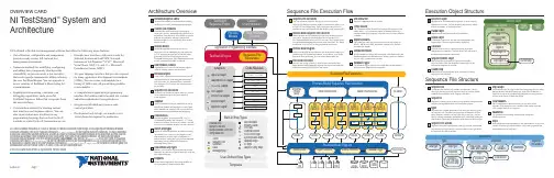
StatementLaMessagePopupLists steps in the sequence and step group for the sequence file you select in the list bar.E x e c u t i o n V i e wDisplays the threads, call stack, and steps for the execution you select.R e p o r t V i e wDisplays the report for the execution you select.Displayssequences and other items in a sequence file.Templates List Organizes custom sequences, steps, and variables you can use as templates for building sequence files.Step Settings Pane Specifies the settings for the step, such as code module parameters, switching, flow control, and post actions.Analysis Results Pane Displays the analysis results for the current TestStand Sequence Analyzer project and for each sequence file and workspace file you analyze.Workspace PaneManages projects for source code control (SCC) integration and deployment. TestStand integrates with third-party SCC packages to add files, obtain the latest versions of files, and check files in and out. Use TestStand project (.tpj ) files to organize sequence files and code module files in folders.Sequence Hierarchy WindowDisplays a graph of the sequence call and callback relationships among sequence files and sequences to more easily visualize, navigate, and maintain test sequences.Variables Pane Displays globals, variables, parameters, and properties, including the values, that steps canaccess at run time.Displays the threads, call stack, and steps an execution runs. When execution completes, displays the report for the execution.Watch View Pane Monitors the values of specified variables, properties, and expressions during an execution.Threads PaneContains a list of threads in the current execution.Output Pane Displays output messages thatexpressions and code modules post to the TestStand Engine.Call Stack PaneDisplays the nested sequence invocations for the thread you select.Types WindowContains definitions of custom datatypes and step types all sequence files User Manager WindowAdministers users for the test station, groups to which users belong, login names, passwords, and privileges.Documentation OverviewGuide to TestStand Documentation topic in the NI TestStand Help contains links to all the TestStand documentation in electronic format and recommends the order in which you examine the documentation. Select Start»All Programs»National Instruments»TestStand» Documentation»NI TestStand Help or select Help»NI TestStand Help in the sequence editor to launch the NI TestStand Help NI TestStand Release NotesUse this document to learn about system requirements, installationinstructions, information about new features, and other changes since the Getting Started with TestStandUse this manual to familiarize yourself with the TestStand environment and the basic features you use to build and run test ing LabVIEW and LabWindows/CVI with TestStandUse this manual to learn how to use LabVIEW and LabWindows/CVI NI TestStand System and Architecture Overview CardUse this card to learn about the overall architecture of TestStand and as a reference for key TestStand concepts.NI TestStand User Interface Controls Reference PosterUse this poster as a reference of the properties, methods, and events found in the TestStand UI Controls API, as well as an illustration of the built-in connections between the TestStand UI Controls.NI TestStand API Reference PosterUse this poster as a reference of the properties, methods, and events found in the TestStand API, as well as an illustration of API inheritance.Configure the settings for deploying a test system, including the components to install and the installer settings.。
NI 中国地区合作伙伴网络National Instruments (NI) 的产品为用户提供无可比拟的强大功能、高灵活性及高效率,帮助您开发自己的测试、测量与自动化解决放案。
•如果您已经拥有了NI产品,可是却面临着时间紧促、技术力量匮乏或其它困境,您可依靠我们世界各地的系统联盟成员提供技术咨询或系统集成服务。
希望了解NI公司全球范围内的合作伙伴和系统联盟详情,请访问>> /alliance在中国地区,我们为您提供以下系统集成商、系统咨询商和代理商的信息,您可根据自己的实际需求选择联系:系统集成商北京经纬恒润科技有限公司地址:北京市海淀区西小口路66号东升科技园北领地B1号楼邮编:100192电话:***********传真:***********E-mail:**********************北京中海技创科技发展有限公司地址:北京市复兴路24号三干所中海公司邮编:100852电话:***********/66700485传真:***********-840E-mail:**********************沈阳普华蓝鹰科技有限公司地址:沈阳市沈河区朝阳街260号708室邮编:110011电话:***********传真:***********天津亿为特电子科技有限公司地址:天津新技术产业园区华苑产业区华天道8号海泰信息广场C-1001邮编:360012电话:***********传真:***********青岛技拓电子科技有限公司地址:青岛崂山区同和路728号6号楼邮编:266035电话:************传真:************上海聚星仪器有限公司地址:上海市张东路1387号集电港二期0幢2号2-3楼邮编:201203电话:***********传真:***********E-mail:*****************.cn上海华穗电子科技有限公司地址:上海闵行漕河泾开发区浦江高科技园新骏环路245号D幢311室邮编:201114电话:***********传真:***********E-mail:***************.cn上海其高电子科技有限公司地址:上海杨浦区国权路43号财富国际广场银座2208邮编:200433电话:***********传真:***********E-mail:******************上海尚毅测控技术有限公司地址:上海市浦东新区康桥路787号中天科技商务园10号楼205室邮编:201315电话:***********传真:***********E-mail:***************上海远宽能源科技有限公司地址:上海浦东金桥路939号宏南投资大厦909室邮编:201206电话:***********传真:***********E-mail:**********************上海保旭机电工程有限公司地址:上海浦东新区沪南路2653号电话:***********传真:***********E-mail:**************睿孚(上海)测试技术有限公司地址:上海浦东张衡路500号张江高科园407号1幢邮编:201204电话:***********E-mail:******************上海科梁信息工程有限公司地址:上海市宜山路829号海博新大楼二楼邮编:200233电话:***********传真:***********E-mail:*******************苏州凌创电子系统有限公司地址:苏州工业园区娄葑镇创投工业坊17号厂房邮编:215122电话:************传真:************网址:敏腾视觉科技(深圳)有限公司地址:深圳罗湖区嘉宾路20号爵士大厦13B20室邮编:518010电话:************传真:************E-mail:*****************富连达科技有限公司地址:广东深圳福田区车公庙泰然工业区劲松大厦7C邮编:518040电话:************传真:************E-mail:******************.cn珠海市精实测控技术有限公司地址:广东珠海斗门区新青科技工业园区新青三路洋青街1栋电话:***********传真:***********E-mail:******************深圳市众鑫丰科技有限公司地址:广东深圳西乡镇宝民二路贤基大厦1栋8L邮编:518102电话:************传真:************四川旭测科技有限公司地址:四川成都武侯区武兴二路17号力德时代13栋4层3号邮编:610017电话:***********传真:***********网址:成都方拓测控有限公司地址:四川成都金府路593号金府银座C座1404邮编:610030电话:***********传真:***********网址:系统咨询商中科华核电技术研究院有限公司北京分公司地址:北京海淀三环内北京市海淀区中关村南大街6号中电信息大厦1108室邮编:100086电话:***********传真:***********大连智达科技有限公司地址:大连软件园路6号邮编:116023电话:************传真:************上海思晋智能科技有限公司地址:上海市松江区车墩镇业东路19号邮编:2017电话:***********传真:***********上海湃梭信息科技有限公司地址:上海浦东金桥金湘路201弄15号1837室(禹州国际三期1号楼)邮编:201206电话:***********传真:***********苏州恩汇测控技术有限公司地址:江苏苏州新区金枫路216号东创科技园2号楼303室邮编:215000电话:************传真:************南京同尔电子科技有限公司地址:江苏南京江宁开发区高湖路96-3号邮编:211100电话:************传真:************南京派格测控科技有限公司地址:江苏南京江东中路186号宏普捷座1号楼702室邮编:210019电话:***********传真:***********武汉华科同创科技有限公司地址:武汉东湖开发区高新大道999号未来科技城海外人才大楼A-4楼619 邮编:430075电话:***********传真:***********邮箱:****************武汉市通力自控技术有限公司地址:湖北武汉武昌区武昌区石牌岭118号邮编:430070电话:***********传真:***********广州创华电子科技有限公司地址:深圳市西丽九祥岭工业区12栋3楼邮编:518055电话:************传真:************代理商北京金品智测控技术有限公司地址:北京海淀区三环四环间知春路27号量子芯座大厦10层1003室邮编:100191电话:***********传真:***********E-mail:***************北京中航科讯技术有限公司地址:北京海淀三环四环间中关村东路66号世纪科贸大厦C座605 邮编:100080电话:***********/52780522传真:***********E-mail:****************沈阳永诚科技有限公司地址:沈阳浑南新区浑南四路一号富腾国际大厦A座2119邮编:110180电话:***********传真:***********E-mail:***********************武汉中创融科科技有限公司地址:武汉市武昌区和平大道666号6幢1506室邮编:430000电话:***********传真:***********E-mail:******************南京聚擎测控技术有限公司地址:江苏省南京市珠江路680号308室邮编:210016电话:***********E-mail:**************.cn。
【NI教程】测试系统的不二之选:系统源测量单元(SMU)目录1. 基于NI SourceAdapt技术的 NI PXIe—4139系统源测量单元2. NI PXIe—4139 技术细节3. 应用示例——DC-DC转换器测试4. 应用示例-—LED特性描述5. SMU助力您的下一个测试系统1。
基于NI SourceAdapt技术的 NI PXIe—4139系统源测量单元源测量单元(SMU)是一种精密测量仪器,可同时对同一通道的电流和电压进行同步源测量。
该功能使得源测量单元成为从精准直流电源到记述分立元件或集成电路等半导体组件的特性等各种应用的理想之选。
某些源测量单元针对特定的应用或者需求作了优化,例如泄露测试、大功率IV扫描、为具有快速瞬态响应的移动设备供电。
这些仪器完美地提供了某一特定的功能,但是您可能需要多个这样的源测量单元来完全记述需要各种不同激励或功能的设备的特性。
或者,您也可以选择系统源测量单元,它将高功率、高精度、高速源测量功能集成到单个仪器上,使您能够执行各种不同的功能以及通过同一接口进行各种不同的设备测试。
这不仅简化了连接,而且减少了使用仪器的种类和数量,降低了测试系统的占地空间和总体成本。
NI PXIe—4139将传统的箱式源测量单元的高功率和精确度以及NI技术集于一身,具有更快速、更灵活、更小巧的特性。
这种结合使得NI PXIe-4139不仅能够实现传统源测量单元之外的功能,而且变成一款多功能的仪器,可用作为:•精准电源•快速瞬变电源•电压表、电流表或欧姆表•隔离高压/电流数字化仪•高电压/电流序列发生器•脉冲发生器•可编程负载•低频交流阻抗计将多种功能集成到单个仪器使得NI PXIe-4139成为测试各种不同设备的理想之选,这些设备可能包含以下需求:•高功率输入输出,同时具有高速采样功能,例如电源管理集成电路(PMIC)•高速瞬态响应,例如射频电源放大器•精准测量及大功率脉冲扫频,例如功率晶体管和高亮度LED•通过同一接口进行精准IV和低频电容测量,例如微型机电系统设备(MEM)由于NI PXIe-4139的模块化特性和紧凑的尺寸,您可以将几个源测量通道集成到混合信号自动化测试应用中,或者借助单个4U PXI机箱中的17个源测量单元通道来搭建高密度半导体测试系统。

基于 NI实时控制器的六自由度平台测控系统设计与实现摘要:六自由度平台作为一种全新的模拟器,用于航天空间运动姿态方面的模拟和规划,在六自由度平台的行程范围内,可以凭借其强大的功能去重新演绎各种空间运动,有着六种自由运动的维度,通过对六个液压作用气的精确控制和解耦算法,可以实现不同自由度的位子控制。
而本文将着重分析依托NI虚拟器基础上的六自由度平台测控系统,了解该系统运行的可靠性和安全性。
以通用计算机作为核心,在硬件平台基础上,由用户设计定义,具有仿真面板,有测试软件实现测试功能的一种全新计算机仪器系统,也有着强大的功能优势。
关键词:NI实时控制器;六自由度;系统设计前言:六自由度并联运动平台有着结构稳定、效率高且承载能力大等多方面的特点,兴起以来逐渐广泛地应用到如汽车、飞机等一些运动模拟实验设备,也取得了十分理想的成果。
在六自由度运动平台测控系统中,需要积极满足其高时效性和精确度,更要具备极强的图形图像交互功能。
而基于NItime的六自由度运动进程平台测控系统可满足六自由度运动平台实时测控的高要求[1]。
1.基于NI实时控制器的六自由度平台概述及系统结构1.概述六自由度运动平台可以实现对于原有轨迹的在线跟踪和监测,作为一种可以为航空飞行提供飞行模拟或是运动人模拟的机构,在应用到航空航天领域的同时,也能够运用在人们的日常生活中,作为一种娱乐体感游戏的形式出现,有着强大的功能,而本文依托NItime虚拟器分析六自由度运动平台的控制策略,能够缓解以往可靠性、时效性不高等控制问题。
以通用计算机作为核心的应届平台上,可以由用户自定义,且有着以下几点优势,首先使用了基于NItime虚拟仪器后,能够灵活配置各类关卡,增加了硬件的灵活性与多样性。
其次,选择了Lab view开发软件,能够简化传统的软件研发方式,Lab view作为一种新型的图形化编程工具,也是所见即所得的可视化工具,建立了人机界面后能够提供大量的控制对象内容,有利于图形化编程语言的落实。
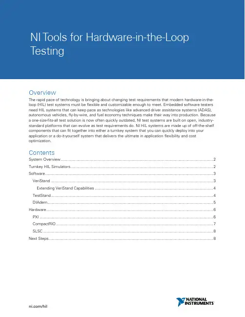
NI T ools for Hardware-in-the-LoopT estingOverviewThe rapid pace of technology is bringing about changing test requirements that modern hardware-in-the-loop (HIL) test systems must be flexible and customizable enough to meet. Embedded software testers need HIL systems that can keep pace as technologies like advanced driver assistance systems (ADAS), autonomous vehicles, fly-by-wire, and fuel economy techniques make their way into production. Because a one-size-fits-all test solution is now often quickly outdated, NI test systems are built on open, industry-standard platforms that can evolve as test requirements do. NI HIL systems are made up of off-the-shelf components that can fit together into either a turnkey system that you can quickly deploy into your application or a do-it-yourself system that delivers the ultimate in application flexibility and cost optimization.ContentsSystem Overview (2)Turnkey HIL Simulators (2)Software (3)VeriStand (3)Extending VeriStand Capabilities (4)TestStand (4)DIAdem (5)Hardware (6)PXI (6)CompactRIO (7)SLSC (8)Next Steps (8)System OverviewWith NI’s open, flexible HIL solutions, you can make customizations to fit your specific needs. Using a modular architecture, easily upgrade the platform with added functionality to future proof your test systems and meet the requirements of the most demanding embedded software test applications. Compared to competitors, NI ’s performance capabilities make it the best option for testing innovative control systems.Figure 1 below shows how the various hardware and software components are assembled into an HIL system. The system includes software for data manager and test automation in addition to the HIL test execution and interface. Below the software are two different hardware platforms for modular I/O and a third that is used for application-specific switching, loads, and signal conditioning. This last one is then connected to the device under test (DUT) through various connectivity options, depending on the device. Figure 1. An HIL system built on NI components offers the ultimate in flexibility because it is built onmodular, off-the-shelf components.Turnkey HIL SimulatorsFor a turnkey system that is ready to deploy but still built to fit your exact application requirements, you can look to NI HIL specialty partners around the globe who build and deliver HIL Simulators. These partners have extensive experience in integrating NI hardware and software as well as the vertical PXI or CompactRIOTest Manager TestStandHIL Engine and UI VeriStandEnvironment SimulationPlant ModelNetworkBuses Analog CameraFrames RF Digital SLSC SLSC SLSC | Load Plates | Physical DeviceI/OSignal ConditioningFault InsertionLoads Bulk ConnectorDIAdem Data ManagementDUT ECU | LRU Physical Deviceapplication of HIL in automotive, aerospace, and other industries. These systems are built to exact specifications and architectures defined by NI and on NI components to ensure a consistent quality and user experience anywhere in the world.With industry-leading customizability, HIL Simulators help you easily adapt to changing test requirements across a wide variety of application areas, including ASAS, electrification, and advanced sensor integration with cameras, radar, and ultrasonics. Additionally, these simulators provide easier test system commissioning and system integration so you can find more engine control unit (ECU) defects faster.NI HIL Simulators are built to integrate into your existing workflow while still giving you the flexibility to adapt to future requirements by including features like the following:∙Model integration from more than 20 simulation environments, including The MathWorks, Inc.Simulink® software∙Fault injection for networks and electrical systems∙Electrical load integration∙RF and camera I/O to keep pace with the latest industry trends∙User-programmable FPGA-based I/O for advanced models∙Flexible bus support including CAN, LIN, FlexRay, ARINC, AFDX, and MIL-STD-1553∙Unlimited expansion capabilities through multiple system connectionsFigure 2. HIL Simulators are turnkey HIL systems built on NI’s open platforms and delivered by a vetted NI HIL specialty partner with extensive industry experience.SoftwareVeriStandVeriStand is a software environment for configuring real-time test and HIL applications. Out of thebox, VeriStand can help you construct a multicore-ready real-time engine to execute tasks such as real-time stimulus generation, data acquisition for high-speed and conditioned measurements, and calculated channels and custom channel scaling.VeriStand can also import control algorithms, simulation models, and other tasks from both LabVIEW software and third-party environments. You can monitor and interact with these tasks using a run-time editable user interface that includes tools for value forcing, alarm monitoring, I/O calibration, and stimulusprofile editing. Although you don’t need programming knowledge to use VeriStand, you can customize and extend it with a variety of software environments such as LabVIEW, ANSI C/C++, ASAM XIL, and others for modeling and programming.VeriStand is architected to have a real-time engine that runs independently from the user interface to ensure the determinism of the system you are running.Figure 3. VeriStand is NI’s HIL testing software and offers model execution, stimulus generation, da ta acquisition, customizable UI, and logging among other features.Extending VeriStand CapabilitiesVeriStand has an open framework that you can use to add specific functionality with LabVIEW. Create add-ons to add support for specific hardware or even create new software functionality that is nonnative. Both NI Alliance Partners and NI have already deployed a number of add-ons that you can download from the community.VeriStand also provides a .NET-based API that you can use to create custom interfaces for VeriStand or to implement automation of the configuration and/or operation of VeriStand applications. For example, you can use the API library to create a custom configuration window that limits the changes a user can make to a VeriStand application or to simplify the configuration process by making it possible to specify the application parameters in a spreadsheet. Or you could automate the operation of a VeriStand application or create a completely custom run-time interface. These .NET-based APIs can be used by LabVIEW, TestStand, and a variety of other environments that can use .NET interfaces like Python. TestStandTestStand is a ready-to-run test management software that is designed to help you develop automated test and validation systems faster. You can use TestStand to develop, execute, and deploy test system software. In addition, you can develop test sequences that integrate code modules written in any test programming language. Sequences also specify execution flow, reporting, database logging, and connectivity to other enterprise systems.You can use TestStand to automate an HIL test application by calling the VeriStand .NET-based execution API. TestStand can also manage hardware and software from multiple platforms in a single TestStand sequence. For example, it can automate VeriStand real-time sequences running on an NI PXI real-timecontroller, while simultaneously controlling a third-party instrument using its native IVI driver support. After you run your test, you can log test result information in a customizable report or database automatically. Additionally, systems written in TestStand integrate with existing source code control, requirements management, and data management systems.You can also integrate TestStand into third-party test management and test generation software platforms. For example, you can use TestStand with MaTeLo from All4Tec to generate automated tests based on your application requirements. Whether you would like to use TestWeaver with VeriStand or MaTeLo with TestStand, you can create a test system to not only automate tests but also automatically generate unit tests to make your ECU fail. This helps you focus on testing embedded software thoroughly instead of writing new test scripts from scratch.Figure 3. TestStand is NI’s test automation software and can be used to automate VeriStand for fasterand more efficient testing.DIAdemSuccessful engineering enterprises share characteristics such as consistent data logging, analysis, and effective data management. This is especially true of HIL test applications where design and test teams must collaborate to ensure embedded software and mechanical system product quality. Implementing a standard, automated means of data analysis and report generation helps you view data in a consistent way, improves test efficiency, and makes data much easier to find and interpret. You can use VeriStand with DIAdem to quickly and easily log data, perform post-processing, and generate reports—all fromthe VeriStand UI tools.DIAdem is a single software tool that you can use to quickly locate, load, visualize, analyze, and report measurement data collected during data acquisition and/or generated during simulations. It is designed to help you quickly access, process, and report on large volumes of scattered data in multiple custom formats to make informed decisions.Figure 4. DIAdem is industry-leading data mining, analysis, visualization, and reporting software. HardwarePXIPXI is a rugged PC-based platform for measurement and automation systems. PXI combines PCI electrical-bus features with the modular, Eurocard packaging of CompactPCI and then adds specialized synchronization buses and key software features. PXI is both a high-performance and low-cost deployment platform for a wide range of applications that includes HIL test. Developed in 1997 and launched in 1998, PXI is an open industry standard governed by the PXI Systems Alliance (PXISA), a group of more than 70 companies chartered to promote the PXI standard, ensure interoperability, and maintain the PXI specification.A major benefit of the PXI platform for HIL is the wide range of I/O options that can be integrated into the test system. As the automotive industry evolves to incorporate new technologies, such as automotive radar, cameras with onboard image processing, V2X, and real-time GNSS position tracking, HIL systems must also evolve to verify the safe operation of these technologies. With available vision, high-performance FPGAs, and RF modules that meet the needs of the latest automotive standards, such as 77-82 GHz radar, the PXI platform is uniquely positioned to meet the demands of these new test requirements.In most cases, PXI is the best solution for HIL testing. It provides high channel count and density, the broadest availability of I/O, and the highest processing capability available. In addition to high-performance hardware, PXI also offers the best software experience for HIL testing, as it supports the most modeling environments and seamless DAQ hardware support.Figure 5. PXI is a high-performance, industry-standard I/O platform with built-in real-time processors, user-accessible FPGAs, and modular I/O including network buses, analog and digital I/O, and camera andradar I/O and simulation capabilities.CompactRIOCompactRIO is a rugged hardware design in a compact form factor that is ideal for most harsh environments as well as lab settings that require a small physical footprint. Although typically providing lower computational performance than PXI, CompactRIO offers high-performance processing and heterogeneous computing elements including ARM-based Xilinx Zynq SoCs as well as quad-core Intel Atom processors and Xilinx Kintex-7 FPGAs. CompactRIO also includes signals with measurement-specific signal conditioning, built-in isolation, and industrial I/O.CompactRIO is an ideal fit for benchtop HIL systems. It doesn’t have as many I/O options as PXI, but the compact form factor and lower price make it a great choice for unit testing of ECUs that require integrated processing and FPGA performance such as ECU testing.Figure 6. CompactRIO is a smaller, modular I/O platform well suited to benchtop HIL testing. It also comes with built-in real-time processing, user-accessible FPGAs, and modular I/O.SLSCSLSC extends PXI and CompactRIO measurement hardware with high-power relays for signal switching, power loads, and additional inline signal conditioning capability. The system consists of a chassis with built-in active cooling that can host 12 modules. SLSC plug-in modules can operate in the chassis in three different modes: standalone, pass through, or cascaded. You can use cascaded mode to implement functionality like signal fault insertion. You can select from a variety of NI and third-party modules or create your own based on a detailed hardware and software development kit from NI.SLSC is designed to simplify overall system integration, reducing system point-to-point wiring by accumulating signals and using standard cables. Each SLSC chassis consists of an SLSC digital bus that is used to discover, configure, and set parameters on the individual modules. Signals pass through SLSC modules either from the front connector or the rear expansion connector. You have the flexibility to design your own secondary backplanes to reduce system wiring using a custom application-specific backplane integrating the signal flow.Figure 7. SLSC is an open architecture for standardizing the switches, loads, and signal conditioning thatare often custom for each HIL application.。
• 163 •科技动态中国航天成功试验减速“神技”航天科技五院508所正在开展国内首次新型充气式再人减速技术(IR D T)飞 行演示验证试验,验证此项技术的工作原理、工作程序和多项关键技术。
这次试验的飞行器呈“飞碟”状,周 身被厚厚的气囊包裹。
I R D T技术基于空间充气展开结构的设计理念,集成了 再人减速过程中的热防护、气动减速、着 陆缓冲、水上漂浮等功能,能够实现航天器的承载、减速、防热一体化设计,使其 再防热大底、降落伞、缓冲气囊等附属设备。
国曾开展过I R D T的试验,但 试验并未完全成功。
为此,N A S A安排了 密速减速器(L D S D)技术验证。
:L D S D被一为“能够规则的技术”。
该技术能使人类将10倍 于“”重量的载。
N A S A三次开展LD SD空试验,了证明了L D S D技术的价值。
未来,随着该技术的发展,配合 五成的多,使着陆15t。
此,技术能减着陆器气动减速的飞行,着陆,并实现着陆,的。
中国的相关技术,原理为。
IR D T技术于空间科试验试验和的速行、。
国正在基于空间充气展开防热、等技术,开成本、高承载比特征的新型空间运输飞行器,为空间行运输,远资投送、回收等供支 撑,计划于2019 完成首飞。
该技术也能为深空器安全着陆提供帮助。
我国半导体S iC单晶粉料和设 备生产实现新突破日,中国电子科技集团公司第二研究所(简称中国电科二所)自主研发和 生产的100台碳化硅(S iC)单晶生长设备正在高速运行,S iC单晶就在这100台设备里“奋力”生长。
S iC单晶是第三代半导体,以其特有的大禁带宽度、高临界击穿场强、高电子迁移率、高热导率等特性,成为制作温、高频、大功率、抗辐照、短波发光及光电集成器件的理想,是新一代g达、卫星通信、高压输变电、轨道交通、电动汽车、通信基站等领域的核心材,的和广阔的I前景。
纯S iC粉料是S iC单晶生长的关键原,单晶生长炉是S iC单晶生长的核心设备,要想生长出的S iC单晶,在纯S iC粉料和单晶生长炉条件下,对生产工艺进行设计、调试和化。
NI技术在设备远程故障诊断中的应用"分别采用 LabVIEW G Web Server技术和 DataSocket技术实现诊断对象的远程状态监控;并基于Data Socket技术开发一个多功能的 CSCW远程协同故障诊断平台。
"- 天宏张, 南京航空航天大学能源与动力学院试车台远程监控系统网络环境The Challenge:将诊断设备现场的监测仪表延伸到 Internet 上,并提供基于 CSCW的协同诊断工作环境。
The Solution:采用NI的 LabVIEW、 Internet Developers Toolkit、 ComponentWorks 分别实现了虚拟仪器的远程应用、 CSCW的协同诊断工作环境,为设备远程故障诊断提供了强有力的手段。
Author (s):天宏张 - 南京航空航天大学能源与动力学院1. 介绍网络化的虚拟仪器可以为远程故障诊断提供形象生动的现场资源,增强临场感。
CSCW技术可以支持多个专家在网络环境下实现协同诊断,充分体现远程会诊的思想。
本文分别采用 NI 的 LabVIEW GWeb Server 技术和 DataSocket 技术实现诊断对象的远程状态监控;并基于 DataSocket 技术开发一个多功能的CSCW远程协同故障诊断平台。
2.虚拟仪器网络化1. 1 概述虚拟仪器网络化是指将工作于试验现场的虚拟仪器通过网络扩展到远程应用领域。
作为虚拟仪器领域的领头羊,NI公司在虚拟仪器领域取得了丰硕成果。
随着 Internet 技术的飞速发展, NI 更是全力出击,分别以 DataSocket 技术、RDA技术、 OPC技术为基础开发了能够实现远程监控的多种软件平台和工具,如 Internet DevelopersToolkit (简称IDT)、 Lookout 等。
IDT 是NI 的面向G语言应用环境的网络应用开发工具包。
IDT提供了G 环境下的虚拟仪器与 Internet连接的手段,从而实现在Internet 上存取数据或将虚拟仪器的前面板(Front Panel)发布到 Internet 上。
NI Measurement Studio 8.5加速提升远程监测与控制功
能
佚名
【期刊名称】《国外电子测量技术》
【年(卷),期】2008(27)7
【总页数】1页(P81-81)
【关键词】;自动化软件;AJAX;控制功能;远程监测;应用程序;NI
【正文语种】中文
【中图分类】TP393.092;TP311.52
【相关文献】
1.NI发布Measurement Studio 8.1进一步简化远程监控功能的操作 [J],
2.NI Measurement Studio 8软件通过ASP.NET具有远程检测和控制功能Measurement Studio为Microsoft Visual Studio 2005提供全面的支持 [J],
3.NI Measurement Studio 8软件通过ASP.NET具有远程检测和控制功能 [J],
4.NI Measurement Studio 8.5加速提升远程监测与控制功能 [J],
5.NI Measurement Studio 8软件具有远程检测和控制功能 [J],
因版权原因,仅展示原文概要,查看原文内容请购买。