转子多断条笼型感应电动机建模及导条电流分析硕士的设计
- 格式:doc
- 大小:1.54 MB
- 文档页数:76

高压电动机转子断条的原因分析及处理摘要:高压交流鼠笼型电动机在电力生产过程中运十分广泛。
但由于原理、结构、机械、制造、工艺、材质、运行的等等一系列复杂的原因共同作用,导致了笼型电机断条事故,由断条所引发的事故占全部电机事故的35%。
分析和解决断条问题是电力生产中迫切需要解决的问题。
本文从多方面分析了笼型电机的断条原因,并针对其原因提出了解决方案,着重从工艺上进行叙述。
由于本人从事电机修造的时间不长,对这方面的研究还有待进一步探讨,希望各位专家能提出宝贵意见,以便以后能够解决更多的现场问题。
关键词:电机;笼条;故障;分析;处理1 前言异步电动机是一种将电能转变为机械能的交流电动机,又称感应电动机,高压异步电动机是指额定工作电压为3~10KV的交流电动机。
在电力生产过程中,高压电机广泛运用在汽轮机及锅炉辅机设备中,如球磨机拖动电机等。
重载启动电机,在启动过程中,由于启动时间长,启动力矩大,易造成笼条断裂,给安全生产造成影响。
2 造成笼条断裂的主要原因1)启动时转子笼条温度很高,使机械强度下降根据电机的堵转等值电路可知其基本方程式=可知,由于定、转子实际阻抗Z1、Z2均很小,因而异步电机启动时的定转子电流都将很大的,造成转子笼条导体的温度升高,根据计算,短时笼条温度可达300℃,机械强度下降,容易断裂。
异步电机启动时起动电动很大而起动转矩不大,其主要原因是起动时转子功率因数很低。
由cosφ2st=可知由于x2>>r2,故cosφ2st≈0.2左右,这表明起动电流中主要是电感性的无功电流,它使供电系统的电压大幅下降,使起动转矩下降为额定转矩的0.9倍,而由于系统电压的下降使得很启动的时间进一步延长,而加剧转子笼条的损坏断裂。
2)为了使启动转矩有所提高,改善电机的启动特性,大多数重载启动电机都采用了深槽式或双笼式结构。
内笼选用工业纯铜为原料,材质一般为T1、T2;外笼一般采用黄铜材料,其电阻较大,有助于起动特性的改善,其机械强度较高,增强抗断条能力。
【摘要】异步电动机广泛应用于各个领域。
目前笼型异步电动机转子笼条在使用过程中经常发生断裂、断条并从转子铁芯槽中脱出等故障,致使发电机停止运行,给生产造成很大影响。
对此,基于转子笼条的形状对电动机进行重新设计与改造,从而大大减少此类故障的发生,提高生产效益和安全。
1前言异步电动机特别是笼型异步电动机具有结构简单、维修成本较低、运行可靠性较高等优点,因此,在日常生活、工厂设备、港口码头、油田煤矿等各个领域中应用非常广泛,担负着很重要的任务。
在发电厂中,使用着各种不同电压等级、不同功率的笼型异步电动机,一旦异步电动机发生故障,将会造成发电机无法正常运行,影响电力生产,给社会生产、生活带来损失和不便。
因此,笼型异步电动机是发电厂的重要辅助设备,提高笼型异步电动机的质量,维护好这些设备,让它们一直处于正常的工作状态是一项非常重要的工作,是提高生产效益和安全的关键。
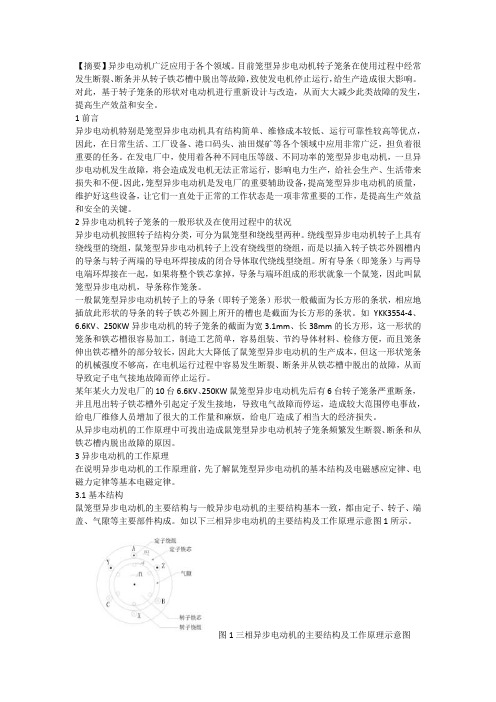
2异步电动机转子笼条的一般形状及在使用过程中的状况异步电动机按照转子结构分类,可分为鼠笼型和绕线型两种。
绕线型异步电动机转子上具有绕线型的绕组,鼠笼型异步电动机转子上没有绕线型的绕组,而是以插入转子铁芯外圆槽内的导条与转子两端的导电环焊接成的闭合导体取代绕线型绕组。
所有导条(即笼条)与两导电端环焊接在一起,如果将整个铁芯拿掉,导条与端环组成的形状就象一个鼠笼,因此叫鼠笼型异步电动机,导条称作笼条。
一般鼠笼型异步电动机转子上的导条(即转子笼条)形状一般截面为长方形的条状,相应地插放此形状的导条的转子铁芯外圆上所开的槽也是截面为长方形的条状。
如YKK3554-4、6.6KV、250KW异步电动机的转子笼条的截面为宽3.1mm、长38mm的长方形,这一形状的笼条和铁芯槽很容易加工,制造工艺简单,容易组装、节约导体材料、检修方便,而且笼条伸出铁芯槽外的部分较长,因此大大降低了鼠笼型异步电动机的生产成本,但这一形状笼条的机械强度不够高,在电机运行过程中容易发生断裂、断条并从铁芯槽中脱出的故障,从而导致定子电气接地故障而停止运行。

《笼型异步电动机多故障智能诊断及分离方法的研究》篇一一、引言笼型异步电动机作为现代工业生产中广泛使用的动力设备,其运行稳定性和效率直接关系到生产线的正常运行。
然而,由于多种因素影响,笼型异步电动机在使用过程中常常会出现各种故障,如绕组短路、轴承磨损、转子断条等。
这些故障不仅影响电机的正常运行,还可能引发更严重的设备损坏和安全事故。
因此,对笼型异步电动机的多故障智能诊断及分离方法进行研究,具有重要的现实意义和应用价值。
二、笼型异步电动机的常见故障及诊断方法笼型异步电动机的常见故障主要包括绕组短路、轴承磨损、转子断条等。
针对这些故障,传统的诊断方法主要依靠人工经验和现场检测,不仅效率低下,而且容易漏诊和误诊。
随着科技的发展,智能诊断技术逐渐应用于笼型异步电动机的故障诊断中,如基于神经网络的诊断方法、基于支持向量机的诊断方法等。
这些方法能够通过分析电机的运行数据,实现对电机故障的快速诊断。
三、多故障智能诊断及分离方法的研究针对笼型异步电动机的多故障智能诊断及分离,本研究提出了一种基于数据融合和模式识别的智能诊断方法。
该方法首先通过传感器实时采集电机的运行数据,包括电流、电压、温度等参数。
然后,利用数据融合技术对采集的数据进行处理,提取出与电机故障相关的特征信息。
接着,通过模式识别技术对特征信息进行分类和识别,实现对电机故障的快速诊断。
在多故障分离方面,本研究采用了一种基于决策树和专家系统的分离方法。
首先,通过决策树对诊断结果进行分类和筛选,确定可能的故障类型和位置。
然后,结合专家系统对可能的故障类型和位置进行进一步分析和判断,实现对电机多故障的准确分离。
四、实验与分析为了验证本研究的智能诊断及分离方法的可行性和有效性,我们进行了大量的实验。
实验结果表明,该方法能够实现对笼型异步电动机的多故障快速诊断和准确分离。
与传统的诊断方法相比,该方法具有更高的诊断效率和准确性,能够大大减少漏诊和误诊的可能性。
同时,该方法还具有较好的鲁棒性和适应性,能够适应不同型号和不同工况的笼型异步电动机的故障诊断。

转子多断条笼型感应电动机建模及导条电流分析中文摘要笼型异步电动机是应用最为广泛的一种电动机,但转子断条故障是这类电机的一种较难避免而又不易检测的常见故障,对重要行业或部门系统的可靠运行影响极大。
因此,深入研究笼型异步电机转子断条故障特征对预防故障发生与扩大,确保系统安全可靠运行具有重要意义。
针对现有各种断条故障诊断技术难以直接获取故障情况下的转子导条电流的局限,本文采用综合矢量法建立了断条故障异步电动机数学模型,通过MATLAB软件对数学模型编程求解,得出了定子电流、转子导条电流,以及转矩、转速等相关数值。
对转子一根、两根、三根、四根断条时的不同位置的故障情况进行数值分析,主要进行了以下几点研究:一方面分析了断条根数对转子电流的影响,得出了用现有测试手段难以获取的转子导条电流分布规律。
电机正常时转子导条电流是大小相等,空间对称的;当电机发生断条故障后,导条电流值的分布不再均匀,连续断条根数越多,导条电流的不对称性也增加。
随着断条数增加,与断条相邻及相距一对极的导条的电流都明显增大。
而无论断条数多少,导条电流空间分布都会按一对极周期的规律变化。
另一方面研究了断条相对位置对转子电流及故障特征的影响,当断条相对位置为一对极距时,最大导条电流值达到相应断条数目的最高值;当相对位置满足对称条件且断条数多于两根时,导条电流的不对称性最小。
如果多断条位置恰好满足磁势对称条件,电机将无故障特征显现。
最后研究了断条故障由单根演变为多根断条的发展趋势,进而预测再次断条的潜在位置。
发现转子有多根断条时,断条会在相距一对极的位置上连续分布。
关键词:异步电动机;转子断条;断条位置;数学模型;综合矢量;Modeling of squirrel cage induction motor with multi-broken rotor bars and analysis of barcurrentAbstractCage induction motor is the most widely used as a motor, but the broken rotor bar fault is difficult to avoid such a motor and not readily detect common faults, major industry or sector for reliable operation of the system a great impact. Therefore, in-depth study of the cage induction motor broken rotor bars fault characteristics and expansion of the prevention of failure, to ensure the system safe and reliable operation is important.For existing fault diagnosis of broken bars fault conditions is difficult to directly obtain the Rotor of the current limitations, this paper established an integrated vector method induction motor broken bars fault mathematical model, using MATLAB software to solve mathematical programming model, obtained stator current, rotor guide of current, and torque, speed and other related values. The rotor one, two, three, four broken bars fault at different locations to conduct numerical analysis, mainly for the following studies:Analysis of the broken bars of one hand the number of rotor currents, obtained with the existing test methods is difficult to obtain the derivative of the current distribution of the rotor. Electrical conductivity of the normal rotor current is the same size, space symmetry; when the motor broken bars fault occurs, the current value of the distribution of lead is no longer uniform, the number of consecutive broken bars of the more lead the asymmetry of the current also increases. With the increasing number of broken bars and broken bars adjacent to and away from the derivative of a pair of polar currents are significantly increased. The number of how many articles without argument, the current spatial distribution of theguide will follow the law of a pair of polar-cycle changes.The other hand, studied the relative position of the rotor broken bars fault characteristics and the impact of current, when the relative position off a pair of polar distance, the maximum conductivity of the current value reaches the maximum number of broken bars corresponding value; when the relative position of the symmetry conditions and meet number of more than two broken bars, the guide of the asymmetry current minimum. If the multi-location is just off of the magnetic potential to meet the symmetry condition, the motor will be no fault features appear.Finally, studies of the broken bars fault by the evolution of a single break of more than root development trend, and thus predict the potential location of broken bars again. Found a number of root rotor broken bars, the bar will be broken away from the position of a pair of polar continuous distribution.Key words: induction motor, rotor-broken-bar, broken-bar position, mathematical model, synthetic vector目录摘要 (I)Abstract (II)第1章绪论 ...................................................................................................... - 1 -1.1 课题背景................................................................................................. - 1 -1.2 本课题国内外的研究现状 ..................................................................... - 2 -1.2.1 感应电机转子导条故障时特征频率的产生机理 .......................... - 3 -1.2.2 转子断条的主要的检测方法 .......................................................... - 5 -1.3 主要研究内容 ......................................................................................... - 7 -第2章无故障感应电机的数学建模 .............................................................. - 9 -2.1 综合矢量的定义 ..................................................................................... - 9 -2.2 数学模型中相关参数的说明 ............................................................... - 11 -2.3 转子根导条时电机数学模型的建立 ................................................... - 12 -2.3.1 定转子磁链综合矢量方程 ............................................................ - 12 -2.3.2 定转子电压综合矢量方程 ............................................................ - 14 -2.3.3 数学模型........................................................................................ - 15 -2.4 实例仿真结果 ....................................................................................... - 19 -2.5 本章小结............................................................................................... - 21 -第3章感应电机转子多断条数学模型的建立 ............................................ - 22 -3.1 转子有一根断条时的数学建模与仿真 ............................................... - 22 -3.1.1 磁链综合矢量................................................................................ - 22 -3.1.2 定、转子电压综合矢量 ................................................................ - 24 -3.1.3 数学模型........................................................................................ - 26 -3.1.4 仿真结果........................................................................................ - 28 -第4章转子导条电流分析 ............................................................................ - 31 -4.1 正常电机转子导条电流的分布 ........................................................... - 31 -4.2 断条根数对转子导条电流的影响 ....................................................... - 32 -4.2.1 单根断条........................................................................................ - 32 -4.2.2 连续多根断条................................................................................ - 33 -4.3 断条位置对转子导条电流的影响 ....................................................... - 36 -4.3.1 两根断条的位置对转子电流的影响 ............................................ - 36 -4.3.2 三根断条的位置对转子电流的影响 ............................................ - 40 -4.3.3 四根及特殊位置断条.................................................................... - 42 -4.4 本章小结............................................................................................... - 44 -第5章转子断条故障演变分析 .................................................................... - 45 -5.1 转子断条发展过程 ............................................................................... - 45 -5.2 故障实例仿真分析 ............................................................................... - 45 -5.2.1 第二根断条为2号导条 ................................................................ - 46 -5.2.2 第二根断条为13号导条 .............................................................. - 47 -5.3 本章小结............................................................................................... - 48 -结论.................................................................................................................. - 49 -参考文献.......................................................................................................... - 51 -致谢.................................................................................................................. - 52 -个人简历.......................................................................................................... - 53 -在学期间发表的学术论文 .............................................................................. - 54 -第1章绪论1.1本课题国内外的研究现状由于感应电机应用广泛,使用环境不尽相同,负载性质也各有所异,电机的故障时有发生。
转子多断条笼型感应电动机建模及导条电流分析中文摘要笼型异步电动机是应用最为广泛的一种电动机,但转子断条故障是这类电机的一种较难避免而又不易检测的常见故障,对重要行业或部门系统的可靠运行影响极大。
因此,深入研究笼型异步电机转子断条故障特征对预防故障发生与扩大,确保系统安全可靠运行具有重要意义。
针对现有各种断条故障诊断技术难以直接获取故障情况下的转子导条电流的局限,本文采用综合矢量法建立了断条故障异步电动机数学模型,通过MATLAB软件对数学模型编程求解,得出了定子电流、转子导条电流,以及转矩、转速等相关数值。
对转子一根、两根、三根、四根断条时的不同位置的故障情况进行数值分析,主要进行了以下几点研究:一方面分析了断条根数对转子电流的影响,得出了用现有测试手段难以获取的转子导条电流分布规律。
电机正常时转子导条电流是大小相等,空间对称的;当电机发生断条故障后,导条电流值的分布不再均匀,连续断条根数越多,导条电流的不对称性也增加。
随着断条数增加,与断条相邻及相距一对极的导条的电流都明显增大。
而无论断条数多少,导条电流空间分布都会按一对极周期的规律变化。
另一方面研究了断条相对位置对转子电流及故障特征的影响,当断条相对位置为一对极距时,最大导条电流值达到相应断条数目的最高值;当相对位置满足对称条件且断条数多于两根时,导条电流的不对称性最小。
如果多断条位置恰好满足磁势对称条件,电机将无故障特征显现。
最后研究了断条故障由单根演变为多根断条的发展趋势,进而预测再次断条的潜在位置。
发现转子有多根断条时,断条会在相距一对极的位置上连续分布。
关键词:异步电动机;转子断条;断条位置;数学模型;综合矢量;Modeling of squirrel cage induction motor with multi-broken rotor bars and analysis of barcurrentAbstractCage induction motor is the most widely used as a motor, but the broken rotor bar fault is difficult to avoid such a motor and not readily detect common faults, major industry or sector for reliable operation of the system a great impact. Therefore, in-depth study of the cage induction motor broken rotor bars fault characteristics and expansion of the prevention of failure, to ensure the system safe and reliable operation is important.For existing fault diagnosis of broken bars fault conditions is difficult to directly obtain the Rotor of the current limitations, this paper established an integrated vector method induction motor broken bars fault mathematical model, using MATLAB software to solve mathematical programming model, obtained stator current, rotor guide of current, and torque, speed and other related values. The rotor one, two, three, four broken bars fault at different locations to conduct numerical analysis, mainly for the following studies:Analysis of the broken bars of one hand the number of rotor currents, obtained with the existing test methods is difficult to obtain the derivative of the current distribution of the rotor. Electrical conductivity of the normal rotor current is the same size, space symmetry; when the motor broken bars fault occurs, the current value of the distribution of lead is no longer uniform, the number of consecutive broken bars of the more lead the asymmetry of the current also increases. With the increasing number of broken bars and broken bars adjacent to and away from the derivative of a pair of polar currents are significantly increased. The number of how many articles without argument, the current spatial distribution of the guide will follow the law of a pair of polar-cycle changes.The other hand, studied the relative position of the rotor broken bars fault characteristics and the impact of current, when the relative position off a pair of polar distance, the maximum conductivity of the current value reaches the maximum number of broken bars corresponding value; when the relative position of the symmetry conditions and meet number of more than two broken bars, the guide of the asymmetry current minimum. If the multi-location is just off of the magnetic potential to meet the symmetry condition, the motor will be no fault features appear.Finally, studies of the broken bars fault by the evolution of a single break ofmore than root development trend, and thus predict the potential location of broken bars again. Found a number of root rotor broken bars, the bar will be broken away from the position of a pair of polar continuous distribution. Key words: induction motor, rotor-broken-bar, broken-bar position, mathematical model, synthetic vector目录摘要 (I)Abstract (II)第1章绪论 ...................................................................................................... - 1 -1.1 课题背景................................................................................................. - 1 -1.2 本课题国内外的研究现状..................................................................... - 2 -1.2.1 感应电机转子导条故障时特征频率的产生机理.......................... - 3 -1.2.2 转子断条的主要的检测方法.......................................................... - 5 -1.3 主要研究内容......................................................................................... - 7 -第2章无故障感应电机的数学建模 .............................................................. - 9 -2.1 综合矢量的定义..................................................................................... - 9 -2.2 数学模型中相关参数的说明............................................................... - 11 -2.3 转子根导条时电机数学模型的建立 ................................................... - 12 -2.3.1 定转子磁链综合矢量方程............................................................ - 12 -2.3.2 定转子电压综合矢量方程............................................................ - 14 -2.3.3 数学模型........................................................................................ - 15 -2.4 实例仿真结果....................................................................................... - 19 -2.5 本章小结............................................................................................... - 21 -第3章感应电机转子多断条数学模型的建立 ............................................ - 22 -3.1 转子有一根断条时的数学建模与仿真............................................... - 22 -3.1.1 磁链综合矢量................................................................................ - 22 -3.1.2 定、转子电压综合矢量................................................................ - 24 -3.1.3 数学模型........................................................................................ - 26 -3.1.4 仿真结果........................................................................................ - 28 -第4章转子导条电流分析 ............................................................................ - 31 -4.1 正常电机转子导条电流的分布........................................................... - 31 -4.2 断条根数对转子导条电流的影响....................................................... - 32 -4.2.1 单根断条........................................................................................ - 32 -4.2.2 连续多根断条................................................................................ - 33 -4.3 断条位置对转子导条电流的影响....................................................... - 36 -4.3.1 两根断条的位置对转子电流的影响............................................ - 36 -4.3.2 三根断条的位置对转子电流的影响............................................ - 40 -4.3.3 四根及特殊位置断条.................................................................... - 42 -4.4 本章小结............................................................................................... - 44 -第5章转子断条故障演变分析.................................................................... - 45 -5.1 转子断条发展过程............................................................................... - 45 -5.2 故障实例仿真分析............................................................................... - 45 -5.2.1 第二根断条为2号导条................................................................ - 46 -5.2.2 第二根断条为13号导条.............................................................. - 47 -5.3 本章小结............................................................................................... - 48 -结论.................................................................................................................. - 49 -参考文献.......................................................................................................... - 51 -致谢.................................................................................................................. - 52 -个人简历.......................................................................................................... - 53 -在学期间发表的学术论文.............................................................................. - 54 -第1章绪论1.1本课题国内外的研究现状由于感应电机应用广泛,使用环境不尽相同,负载性质也各有所异,电机的故障时有发生。