示波器说明书安捷伦---2015.2.9
- 格式:docx
- 大小:1.14 MB
- 文档页数:12
示波器使用方法示波器使用方法2010-05-27 18:47示波器使用方法图解在维修中使用示波器一是查看波形,二是计量波形。
查看波形是否有,是否变形,频率对否,幅度7 h6 j2@%U${2 N9 e大小这些内容都要在显示屏上得到,这就是读屏。
一般示波器的显示屏都有坐标方格刻度,纵向有(I1`k4 b6 B%s:w"Z&I;`八格,横向有十格.横向每格表示一个波形在本格的时间,如该波形一个周期占了四格,那么该波形1 y+^5 _-?-^l:]!K6[的周期是每格时间×4。
每格所表示时间是由时间选择钮位置决定的。
纵向每格表示一个波形的在本格的电压幅度,如该波形共占有四格,那么它的峰峰值就是每格电压×4.附图中有示波器显示屏和时间选择电压选择钮实物照片。
并画出1K赫兹1V的方波信号在不同时间档和电压档显示的波形。
1计量测量时时间选择和电压选择钮中间微调钮(有的示波器微调钮单设在两个钮旁边)要顺时针旋到底。
并利用示波器自带的1K赫兹0.5V(有机型是1V)方波校准信号对仪器进行校准。
2时间选择钮选择的是周期时间,并不是频率。
一秒(SEC)÷周期=频率)Z0 A7?-W"D)F&`*Y 3对被测信号频率要有大概的了解。
如音频在几百赫到几千赫,时间选择钮应在mS(毫秒)范围选择。
B1 L%l5 v*J.R1 g&{9 W彩电视频和行频是15625赫,应在uS(微秒)档选择。
否则看不到完整的波形。
1 G+W4 J"H.N)]O+X 4对被测信号的峰值要有大概的估计,以选择合适的电压档。
不然也看不全波形或太小而不同步。
示波器使用方法图解二功放中的波形功率放大器由前置放大和功率放大两部分组成,叫合并式功放,前置放大有麦克风输入,放大,音量控制,音.f(B3 S,L8 b5 r.f#y调调整,混响调整,线路输入选择,音量音调控制。
Alpha安捷伦B1500A半导体器件分析仪用户!ˉ的GUID安捷伦科技公司声明?安捷伦科技公司2005年,2006年,2007年,2008本手册的任何部分不得转载任何形式或通过任何手段(包括电子电子存储和检索或翻译成外国语言)事先同意MENT和安捷伦的书面同意作为由美国科技公司在美国和国际版权法。
手册部件号B1500-90000版2005年7月第1版,第2版,2005年12月2006年4月第3版第4版,2007年1月2007年6月5日,版第6版,2007年11月2008年10月7日,版安捷伦科技公司5301史蒂文斯溪大道95051美国加利福尼亚州圣克拉拉保证本文档中所含的物质是提供MENT!°为是,±,是苏如有更改,恕不另行通知,在以后的版本。
此外,最大而且,在适用法律法律,安捷伦提供任何保证,明示或暗示,关于本手册的任何信息所载,包括但不不限于隐含保证为杆的适销性和适用性特定用途。
安捷伦不得承担错误或偶然或在相应的损害赔偿连接TION的家具,使用,或每本文件或任何性能所载资料。
应该安捷伦与用户有一个单独的与保修的书面协议在这个物质的范围,涵盖记录与这些冲突条款,在保修则以协议arate中的协议为准。
技术许可硬件和/或软件描述这份文件是依照许可可用于复制或只在雅跳舞的许可条款。
有限权利如果软件在使用的一种表现美国政府的首要合同或道,软件交付和许可!°商业计算机软件!±ADFAR252.227-7014(1995年6月)的定义,或作为一个!°商业项目!FA±定义2.101(a)或°有限计算机软!洁具!±作为定义在FAR52.227-19(六月1987)或任何相当机构法规或合同条款。
使用,重复或disclo的软件肯定是受安捷伦科技nologies!ˉ标准商业许可条款和非DOD部门和美国政府机构没有获得更大而不是限制权利定义在FAR 52.227-19中(C)(1-2)(6月1987年)。

示波器的工作原理时间:2009-05-13 13:42:16 来源:作者:在数字电路实验中,需要使用若干仪器、仪表观察实验现象和结果。
常用的电子测量仪器有万用表、逻辑笔、普通示波器、存储示波器、逻辑分析仪等。
万用表和逻辑笔使用方法比较简单,而逻辑分析仪和存储示波器目前在数字电路教学实验中应用还不十分普遍。
示波器是一种使用非常广泛,且使用相对复杂的仪器。
本章从使用的角度介绍一下示波器的原理和使用方法。
1 示波器工作原理示波器是利用电子示波管的特性,将人眼无法直接观测的交变电信号转换成图像,显示在荧光屏上以便测量的电子测量仪器。
它是观察数字电路实验现象、分析实验中的问题、测量实验结果必不可少的重要仪器。
示波器由示波管和电源系统、同步系统、X轴偏转系统、Y轴偏转系统、延迟扫描系统、标准信号源组成。
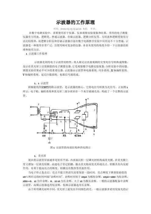
1.1 示波管阴极射线管(CRT)简称示波管,是示波器的核心。
它将电信号转换为光信号。
正如图1所示,电子枪、偏转系统和荧光屏三部分密封在一个真空玻璃壳内,构成了一个完整的示波管。
图1 示波管的内部结构和供电图示1.荧光屏现在的示波管屏面通常是矩形平面,内表面沉积一层磷光材料构成荧光膜。
在荧光膜上常又增加一层蒸发铝膜。
高速电子穿过铝膜,撞击荧光粉而发光形成亮点。
铝膜具有内反射作用,有利于提高亮点的辉度。
铝膜还有散热等其他作用。
当电子停止轰击后,亮点不能立即消失而要保留一段时间。
亮点辉度下降到原始值的10%所经过的时间叫做“余辉时间”。
余辉时间短于10μs为极短余辉,10μs—1ms为短余辉,1ms—0.1s为中余辉,0.1s-1s为长余辉,大于1s为极长余辉。
一般的示波器配备中余辉示波管,高频示波器选用短余辉,低频示波器选用长余辉。
由于所用磷光材料不同,荧光屏上能发出不同颜色的光。
一般示波器多采用发绿光的示波管,以保护人的眼睛。
2.电子枪及聚焦电子枪由灯丝(F)、阴极(K)、栅极(G1)、前加速极(G2)(或称第二栅极)、第一阳极(A1)和第二阳极(A2)组成。


Unique Capabilities.Ultimate Performance.Ultra-High Precision.Thanks to rapid advances in technology,accurate,real-time waveform analysis is more important than ever,especially in digital and IT applications.With its varying brightness and continuous acquisition, the analog scope brings a real-time statistical dimension to the viewed waveform that is simply not possible with digital storage oscilloscopes.Featuring ultra-high brightness and ultra-high speed response that surpasses even the latest digital oscilloscopes,IwatsuÕs ultimate line of analog scopes make it possible to view natural waveforms across the widest possible frequency range with the highest-possible brightness inÒreal timeÓ.So give yourself the analog advantage with IWATSU. Nothing else measures up.ThereÕs a world of waveforms that only Analog cancapture!Specially-designed gate array with built-in CPU Extra-bright, extra-sharp, Japan-made, IWATSU-original CRTIWATSU-developed LSIs and ICs IWATSU-developed preamp ICWide-Bandwidth Analog Oscilloscope Lineup ● DC - 1GHz/600MHz (50Ω) wide frequency bandwidth ● Fastest sweep of 200 ps/div ● Ultra-fast writing speed of 10 div/ns can capture 6 div amplitude, 500 ps rise time pulse● DC - 500MHz (1 M Ω, passive probes areoptional), 4 CH● Sharp traces and high-resolution color display800 x 480 dots● Versatile output interface and documentationfunctions<Built-in printer, LAN interface, ATA card slot,video output (NTSC/PAL)>TS-81000/TS-80600● DC - 470/400/300MHz, 4 CH, 10 traces [SS-7847A]* DC - 470MHz (-3 dB) at 5 mV - 50 mV/div* DC - 440MHz (-3 dB) at 2 mV , 100 mV - 5 V/div● HDTV , NTSC, PAL/SECAM-compatible full TVtriggering with clamping function● ±2% accuracy for vertical axis sensitivity ● Bright and sharp display with 20 kV acceleratingvoltage CRT (Japan made)● Maximum sensitivity of 2 mV/div ● Input offset function ● 6-digit frequency counter ● Quick auto setup ● Save/recall of up to 256 panel settingsSS-7847A/SS-7840A/SS-7830ATS-Series Analog Storage OscilloscopesSS-Series Analog Oscilloscopes4● DC - 50MHz, 2 CH + ext. trigger input, 3 traces(SS-7805A) /DC - 40MHz, 2 CH + ext. trigger input, 3 traces(SS-7804A)● Cursor measurement function● CH2 output● ±2% accuracy for vertical axis sensitivity● Bright and sharp display with 16 kV accelerating voltage CRT (Japan made)● Full TV triggering with TV line selection capability ● 5-digit frequency counter● DC - 100MHz, 3 CH, 8 traces● CH3 sensitivities of 50 mV, 100 mV , 500 mV/div● Save/recall of up to 32 panel settings (SS-7811A only)● Quick auto setup● ±2% accuracy for vertical axis sensitivity● Bright and sharp display with 16 kV accelerating voltage CRT (Japan made)● Cursor measurement/panel settings readout function● Full TV triggering with field and line selection, HDTV● CH2 output ● Maximum sensitivity of 2 mV/div,fastest sweep of 1 ns/div● 5-digit frequency counter● DC - 20MHz, 2 CH + ext. trigger input, 2 traces● Cursor measurement function● ±2% accuracy for vertical axis sensitivity● Full TV triggering with TV line selection capability● 5-digit frequency counter ● Single-sweep function5● DC - 200MHz, 3 CH, 8 traces● CH3 sensitivities of 50 mV, 100 mV, 500 mV/div● Save/recall of up to 32 panel settings ● Quick auto setup● ±2% accuracy for vertical axis sensitivity● Bright and sharp display with 16 kV accelerating voltage CRT (Japan made)● Cursor measurement/panel settings readout function● Full TV triggering with field and line selection, HDTV● CH2 output ● Maximum sensitivity of 2 mV/div,fastest sweep of 1 ns/div● 5-digit frequency counter23451 H igh-resolution, 5.8-inch color LCD (800 x 480 dpi)Provides a sharp, bright waveform display, with color assignment from 7 colors (white, red, blue, yellow,magenta, cyan, green) for persistence and storedwaveforms.2 P C Card slotFor storage of display image and setup data.3 B uilt-in 6-digit frequency counter(2Hz to 1GHz/600MHz, accuracy ±0.01%)4 P ersistencePersistence time selectable from 0 to infinity.Color display also available.5 1GHz maximum frequency bandwidth1GHz/600MHz frequency bandwidth for CH1/CH2;500MHz for CH3/CH4. (SS-101R passive probe isoptionally available)6 2 power supply connectors for active probesFET probes SFP-5A (1GHz)/SFP-4A (800MHz),current probes SS-250 (100MHz)/SS-240A (50MHz) are available as an option.7 D ual delayTwo delay times provided for B sweeps, allowing delayexpansion at two positions.8 P rint screenHard copy to the built-in printer, ATA card and Network9 S ave/RecallUp to 256 panel setups and six reference waveformscan be save/recalled.0 C ursor measurement∆V or ∆t selectable. Simultaneous 4-cursorsmeasurement also available.! Q uick auto setupAutomatically displays the input waveform in theoptimum range. Applicable to both CH1 and CH2with a frequency range from 50Hz to 200MHz.@ B uilt-in printerPrints out the hard copy of displayed waveform.(Printer speed max. 10 mm/sec)* Please visit our Web site, and confirm our recommendation for the PCMCIA card.http://www.iti.iwatsu.co.jp/e/6Video output (Conposite, 1 V)Z axis input(0.5 Vp-p, DC - 5MHz)CH2 signal output(20 mV/div, 500MHz/300MHz)Enhanced documentation functionsBuilt-in thermal printer and versatile outputinterfaceA built-in thermal printer and LAN interface (10Base-T) areprovided so you can output measured data directly orBurn-free and shock-freeSince the waveform is stored by the CCD, CRT phosphorsare protected from burning. Durable construction providesexcellent shock resistance.High accuracy 6-digit frequency counterBuilt-in thermal printer, LAN environment, personal computers, external printers, video recorders, monitors, ATA cards, etc. Various output interfaces are provided.- Remote control through LANRemote control available through LAN*.Delivers video signal (NTSC/VGA) via network.Real time waveform monitor is also available.* Please visit our web site to download the software.http://www.iti.iwatsu.co.jp/- Network printer supportHard copy to network printers, available by using the“Network Printer Gateway” software*.* Please visit our web site to download the software.http://www.iti.iwatsu.co.jp/- NTSC outputDisplayed waveforms can be stored as MovingPicture files using an optional video capture unit.- Image file saving (BMP/JPEG)It is possible to save displayed waveforms to an A TA card.7igh-brightness CRT (Japan made)6-inch, meshless CRT with internal graticule displays waveforms with bright and sharp traces. igh-accuracy 6-digit frequency counterA frequency counter with ±0.0025% accuracy is ave/recall functionUp to 256 different setups with 12-character comments can be saved and recalled.ide frequency bandwidth of DC - 470MHzA)/400MHz (SS-7840A)/300MHz (SS-5 P ower supply output terminals for FET orcurrent probeOptional SFP-5A/4A (DC - 1GHz/800MHz) FETprobe and SS-250 (100MHz)/SS-240A (50MHz)current probe can be used.6 P owerful TV triggeringTV-H, ODD, EVEN or BOTH fields can be selected.Line selection is possible from NTSC: 1 - 525H,PAL (SECAM): 1 - 625 and HDTV: 1 - 1125.7 D irect selection of the cursor measurementAlternates ∆t and ∆V. Up to four cursors can bedisplayed simultaneously. 1 E xternal intensity modulation signal input0.5 Vp-p, DC - 5MHz, ±40 V2 C H2 signal output20 mV/div, DC - 200MHz/50 Ω12341432Rear panel 8Frequency counter All models6-digit: SS-7847A/7840A/7830A,5-digit: SS-7821A/7811A/7805A/7804A/7802A The built-in 6/5-digit counter is accurate within a range of0.0025% / ±0.01% and can measure frequencies between 2Hz and 400MHz. Also shows the trigger signal frequencies.Pedestal clamp function (CH1, CH2) for TV signals SS-7847A/7840A/7830A The amplitude of video signals varies dynamically depending on the picture. This function ensures stable observation. DC offset function (CH1, CH2)SS-7847A/7840A/7830A Convenient when you need to observe a signal with very small amplitude superimposed over a signal with large amplitude. Especially useful when observing high-frequency noise superimposed over video signals or ripple of high-voltage DC power supply.CH2 skew adjust SS-7847A/7840A/7830AThe delay time of CH2 in response to CH1 can be adjusted with a range of 1 ns. Therefore, accurate measurement is possible by compensating for the delay time difference between the DC - 470MHz/400MHz/300MHz (all channels), high-sensitivity of 2 mV/div (CH1, CH2)A DC - 470MHz (SS-7847A)/DC - 400MHz (SS-7840A)/ DC - 300MHz (SS-7830A) for all channels. CH1 and CH2 have max. sensitivity of 2 mV/div, ensuring extremely high-quality waveforms.IWATSU-developed bright, sharp CRT All models T o increase signal stability, a preamp circuit has been provided for the IC.9Panel settings save/recall function SS-7847A/7840A/7830A (SS-7821A/7811A: up to 32 setups)Up to 256 panel setups can be saved together with comments (up to 12 characters).Event trigger SS-7847A/7840A/7830AIn addition to the event delay trigger which allows you to trigger (with DC offset control).● HDD magnetic head measurementOutput waveforms from defectivesectors on a hard disk where errorshave occurred are magnified forobservation.● Large-capacity transmission Digitized video data is sent via a high-speed serial transmission line. The TS-81000 accurately displays subtle variations, such as overshoot of serial data signal waveforms.● Evaluation of power-factor improvement circuit (Power supply)The TS-Series displays jitter-contained waveforms with brightness variations inreal time.● Video signalsThe TS-Series accurately displays details of video signals. It can clearly show slow-repetition video signals with ultra-high brightness via the persistence function. The TS-Series has suitable functions for video signals including an HDTV trigger, two types of video scales, aTV clamp, 4-field selector and dual delay.TS-Series: for observation of complex, intermittent signals● Photo multiplier tubeOutput signal voltage variation detectedby the photo multiplier tube.The TS-Series can display clusters ofirregular single-shot signals at ultra-fastspeeds and displayed in real time withslight brightness differences.● Blue laser diode The read/write signals of laser diodes are getting faster as the density of optical storage media increases. The TS-Series can provide solutions for engineers due to its 1GHz/600MHz frequency bandwidth - the widest in the world.● High power laser waveform High-brightness analog oscilloscopes are needed for continuous low-repetition rate pulse signals. The TS-Series can provide a new safety evaluation method as a high-power laser with video output and LAN interface.10The following shows a comparison of analog and digital waveforms, using calibration waveforms from the EMC static electricity discharging immunity testing equipment. The figure on the left shows a waveform captured by an analog storage oscilloscope, while the figure on the right shows a waveform captured by a digital oscilloscope with a 10 GS/s high-speed sampling frequency. When compared to the analog oscilloscope (on the left), you may see an apparent difference in peak level in the first pulsesection. The observed object is a signal with an amplitude of approximately 800 mV. The peak signal is not captured by the digital oscilloscope, possiblybecause correct observationis not possible with the digitaloscilloscope due toinsufficient sampling speed,depending on the waveformsbeing observed. Although thestatic electricity dischargingtest is just an example,it shows that the TS-SeriesAnalog Storage Oscilloscopecan easily capture extra-highspeed signals of this typeand display the capturedwaveform“as it is” in real time.SS-Series: indispensable for a wide range of requirements● Eye-patterns in optical disc manufacturing process When evaluating optical discs such as Blu-ray Discs, HD-DVDs, CDs or DVDs, eye patterns need to be observed. With this analog oscilloscope, accurate observation of the eye patterns of high-speed and high-density media is easily possible. * Blu-ray Disc signal eye pattern waveform ● Video head frequency modulation signals Input and output signals to/from video heads are frequency modulation waveforms. The voltage of recorded or read-out signals to/from the video heads is specified. To observe these FM signals, an analog oscilloscope is indispensable.* VHS deck head signal waveform ● ATM 155 Mbps signal eye patternsThe standard transmission rate for most networked communication systems is 155 Mbps (STM-1). The amount of jitter can be estimated by observing the signal waveform with the eye pattern and following the pulse mask standard. * 155 Mbps signal eye pattern waveformmeasured with SS-7847A (DC - 470MHz)● Full TV triggering TV-V (ODD field, EVEN field, BOTH fields) and TV-H are available. Line number selection in TV-V mode is useful for detailed evaluation of video signals. HDTV can be selected, as well as NTSC or PAL/SECAM (except for SS-7805A/7804A/7802A)● Switching power supply measurementA switching power supply unit with a higher harmonics measure switches the voltage of a commercial power supply at high speed. In terms of circuit operation, switching stops at the zero cross of the AC power supply. To observe this condition, an analog oscilloscope is required. Analog oscilloscopes are also superior when simultaneously observing voltage and current waveforms. In addition, when magnifying a switching waveform for observation on an analog oscilloscope, no complicated operations are required to triggerthe waveform.Captured by digital oscilloscope (10 GS/s)Captured by analog storage oscilloscope 11— A wide range of options for maximum efficiency and optimum performance ArrayTS-Series and SS-Series Options1213Notes for TS-Series Oscilloscopes"#。
DSOX3PWR 功率量測應用使用者指南s1聲明© Agilent Technologies, Inc. 2007-2009, 2011-2012本手冊受美國與國際著作權法之規範,未經 Agilent Technologies, Inc. 事先協議或書面同意,不得使用任何形式或方法 (包含電子形式儲存、擷取或轉譯為外國語言) 複製本手冊任何部份。
手冊零件編號版本 02.20.0000版本2012 年 7 月 16 日Available in electronic format onlyAgilent Technologies, Inc.1900 Garden of the Gods Road Colorado Springs, CO 80907 USA 保固本文件所含內容係以「原狀」提供,未來版本若有變更,恕不另行通知。
此外,在相關法律所允許之最大範圍內,Agilent 不承擔任何瑕疵責任擔保與條件,不論其為明示或暗示者,其中包括 (但不限於) 適售性、適合某特定用途以及不侵害他人權益之暗示擔保責任。
對於因提供、使用或運用本文件或其中所含的任何內容,以及所衍生之任何損害或所失利益或錯誤,Agilent 皆不負擔責任。
若Agilent 與使用者就本文件所含材料保固條款簽訂其他書面協議,其中出現與上述條款相牴觸之部分,以個別合約條款為準。
技術授權此文件中所述的硬體及/或軟體係依授權提供,且僅可以依據此類授權之條款予以使用或複製。
限制權利聲明美國政府限制權利。
授予聯邦政府之軟體及技術資料僅包含為一般使用者提供的自訂權利。
Agilent 依照 FAR12.211(「技術資料」) 及 12.212 (「電腦軟體」)、國防部 DFARS 252.227-7015 (「技術資料 - 商業條款」) 以及 DFARS227.7202-3 (「商業電腦軟體」或「電腦軟體說明文件」中的權利) 提供此軟體與技術資料之自訂商業授權:安全聲明注意「注意」標示代表發生危險狀況。
安捷伦示波器说明书解决multisim仿真速度慢multisim11.0中仿真时间步长的设定方法multisim10示波器的使用方法——同电子仿真软件MultiSIM 9中的虚拟示波器使用方法2011-06-13 22:16:43| 分类:IC -- 电子| 标签:|字号大中小订阅电子仿真软件MultiSIM 9中的虚拟示波器使用方法朱晓欣(原载《无线电》杂志07年第五期)在电子仿真软件MultiSIM 9中,除了虚拟双踪示波器和虚拟四踪示波器以外,还有两台高性能的先进示波器,它们分别是:跨国"安捷伦"公司的虚拟示波器"Agilent54622D"和美国"泰克"公司的虚拟数字存贮示波器"TektronixTDS2024"。
本刊06年第五期曾对Multisim7中的安捷伦虚拟示波器设置和显示有过简单介绍,读者可以参阅该文相关内容。
本文主要介绍安捷伦虚拟示波器的一些特殊其它功能和美国"泰克"公司的虚拟数字存贮示波器这两台高档次的示波器使用方法。
一、安捷伦虚拟示波器"Agilent54622D"的使用方法举例Agilent54622D虚拟示波器的带宽为100MHz,具有两个模拟通道和16个逻辑通道。
图一是它的放大面板图,它的各个开关、按钮及旋钮的排列和调节都和实物仪器完全一样,我们在自己的电脑里也能享受到使用高档次测量仪器的愉悦,且没有损坏仪器的担忧。
图一一、显示基本波形操作(这里以模拟通道1为例说明)首先在电子仿真软件MultiSIM 9电子平台上调出安捷伦虚拟函数信号发生器和安捷伦虚拟示波器各一台。
并按图二连好电路;双击安捷伦虚拟函数信号发生器图标"XFG1"打开电源开关,不作任何设置使用它的默认值,即:频率1kHz,幅值100mVpp的正弦波(可参阅上期介绍)。
图二然后双击安捷伦虚拟示波器图标"XSC1",打开它的电源开关,见图一中鼠标手指所示。
打开仿真开关,这时可以从安捷伦虚拟示波器屏幕上看到一条水平细红线。
在放大面板处于当前窗口的前提下,将鼠标移至"Y轴量程调节"旋钮上呈手指状,或按住鼠标左键向逆时针方向转;或连续点击键盘上的"↑"键都可以逐渐放大正弦波信号幅度,且屏幕上方"Y轴量程调节指示"数字在减小;将鼠标移至"X轴时间调节"旋钮上呈手指状,或按住鼠标左键向逆时针方向转;或连续点击键盘上的"↑"键都可以使正弦波信号展宽,且屏幕上方"X轴时间量程指示"数字在减小;将鼠标移至屏幕左下角"波形亮度调节"(也可认为是在调整聚焦)旋钮上呈手指状,或按住鼠标左键向顺时针方向转;或连续点击键盘上的"↓"键都可以逐渐加粗正弦波信号波形;将鼠标移至屏幕左下角"Y轴移位调节"旋钮上呈手指状,或按住鼠标左键向顺时针方向转;或连续点击键盘上的"↓"键都可以将正弦波向下移动,相当于真实示波器的Y轴移位旋钮;经以上调整结果,从屏幕上可以看到如图三所示波形,从图上我们通过屏幕上方显示的数据可以读出1kHz正弦波的周期是1mS、幅度为100mV,与安捷伦虚拟函数信号发生器设置相符,波形中心离开X轴为50mV,屏幕上的波形已被适当加粗。
图三二、游标测量功能仍利用上述图二电路,并打开安捷伦虚拟函数信号发生器和安捷伦虚拟示波器电源开关,且安捷伦虚拟函数信号发生器不作任何设置仍使用它的默认值,即:频率1kHz,幅值100mVpp 的正弦波,适当调整相关旋钮得到稳定的波形如图四所示。
点击安捷伦虚拟示波器放大面板上的"Cursor"(光标)按钮,屏幕下方"辅助功能按钮"上方将出现6个绿色矩形框,分别注明为"Source 1"、"X Y"、"X1(或Y1)"、"X2(或Y2)"、"X1-X2(或Y1-Y2)"和"Cursor 40%"等字样,见图四。
图四若要对波形的周期进行精细测量,可先点击"辅助功能按钮"第二个"X Y"绿框下方按钮,选取"X",即"X"下方打上勾表示选中,再点击"X1"绿框下方按钮,这时可以利用游标虚线确定波形一个周期的初始精确位置,将鼠标移到屏幕右面"Cursor"按钮左侧旋钮上,鼠标呈手指状如图五所示,按键盘上的"↑"键或"↓"键,"X1"下方的数字随着变化,使它等于-500us,这实际上就确定了该正弦波形一个周期的初始精确位置;再点击"X2"按钮,按键盘上的"↑"键或"↓"键,使"X2"下方数字等于500us,见图四,这实际上就确定了该正弦波形一个周期的结束时间精确位置,这样就利用了游标虚线准确地确定了正弦波形的一个周期时间。
左上方黑色框中显示"dx=1ms"即正弦波周期为1ms,中间黑色框中显示频率"1/dx=1kHz"。
如果切换测量正弦波形幅度,则对应的"Y1"和"Y2"框显示"-50mV"和"50mV",上方黑色框中显示"dY=100mV",图四中鼠标箭头所指位置为游标虚线"X1"和"Y1"的交叉处,亦即正弦波一个周期的初始时间游标虚线和正弦波的正峰值游标虚线汇合点。
图五三、数学函数运算功能安捷伦虚拟示波器对波形有加、减、乘、除、微分、积分和傅里叶变换等多种运算功能。
下面以两个不同频率的正弦波相减运算、相加运算和相乘运算为例说明之。
首先在电子仿真软件MultiSIM 9的电子平台上创建如图六所示仿真电路。
图六双击安捷伦虚拟函数信号发生器图标"XFG1",打开电源开关,将它的幅度设置成5Vpp,频率用默认值1kHz的正弦波;双击安捷伦虚拟函数信号发生器图标"XFG2",打开电源开关,将它的幅度也设置成5Vpp,频率设置成500Hz的正弦波。
打开仿真开关,双击安捷伦虚拟示波器图标"XSC1",打开示波器电源开关,按下通道"2"按钮如图七中鼠标手指所指,再适当调整两波形的Y轴位置如图七所示。
图七点击"通道参数设置"框中的"Math"按钮见图八左图鼠标手指所指,这时屏幕下方也将出现6个绿色矩形,分别注明为"Setting"、"FFT"、"1×2"、"1-2"、"dv/dt"、"∫vdt",将鼠标点击"1-2"按钮,绿框中出现"√"表示该项功能选中见图八右图屏幕下方鼠标手指所指,这时可以看到屏幕最下方的两波形相减的波形。
图八若要实现两波形相加运算,可再点击一下通道"2"按钮,这时屏幕下方出现3个绿色方方框,用鼠标点击"Invert"(转换)按钮见图九中鼠标手指所指。
实际上这里只是把通道"2"的正弦波上下翻转,即相位改变了180o,执行的仍然是两波形的减法运算,和数学中的1-(-2)=1+2相当,两波形相加结果波形如图九屏幕最下方所示,表面上看两波形相加和相减好像没有大的区别,读者可以用上面游标测量功能来验证一下图八是否是两波形相减的结果,图九是否是两波形相加的结果。
图九再先点击一下图九中的"Invert"(转换)按钮,后点一下"Math"按钮回到图八相减状态;然后点击"1×2"按钮,即可看到两波形相乘的波形如图十所示。
图十二、美国"泰克"虚拟示波器Tektronix TDS 2024使用方法简介在电子仿真软件MultiSIM 9中新增添了一台美国"泰克"虚拟示波器Tektronix TDS 2024,它是一台四通道、200MHz的数字存贮示波器,点击"仪器工具条"中的"Tektronix Oscilloscope"即可调出"泰克"虚拟示波器"XSC1",如图十一所示,双击图标"XSC1"即打开它的放大面板,其面板上的主要功能按钮如图十二所示。
图十一图十二一、普通波形显示操作在电子仿真软件MultiSIM 9的电子平台上搭建如图十三所示仿真电路,并将函数信号发生器设置成1kHz、1Vpp的正弦波信号。
图十三打开仿真开关;双击"泰克"虚拟示波器图标"XSC1",再点击放大面板上的"电源开关"按钮,见图十二左下角,这是在"泰克"虚拟示波器左侧屏幕上即可看见正弦波形,它的Y轴默认幅值为1V;X轴默认时间为2ms,如图十四屏幕下方鼠标箭头所指,并且在屏幕右下角自动显示信号的频率为1kHz。
图十四在放大面板处于当前窗口的前提下,将鼠标移到通道"CH1"上方的旋钮上,鼠标呈手指状,这时可以通过按键盘上的"↑"、"↓"键,改变Y轴的幅度量程刻度从而调整波形的大和小如图十五(左)所示;将鼠标移到通道"HORIZONTAL"栏下方的大圆旋钮上,鼠标呈手指状,这时可以通过按键盘上的"↑"、"↓"键,改变X轴的时间量程刻度从而调整波形的疏和密如图十五(中)所示;将鼠标移到通道"CH1"上方的小圆旋钮上,鼠标呈手指状,这时可以通过按键盘上的"↑"、"↓"键,改变波形在屏幕上的下和上的位置,如图十五(右)所示。
图十五二、用"泰克"虚拟示波器产生调幅波信号举例点击电子仿真软件MultiSIM 9基本界面工具条"Place Source"按钮,在出现的对话框的"Family"栏下选取"COMTROL_FUNCTION_BLOCKS"(控制模块),然后在"Component"栏下选取"MULTIPLIER"(乘法器),将乘法器A1调出放置在电子平台上;再调出两个交流信号源和地线,并分别将两个交流信号源设置成"10MHz、5V"和"2MHz、2V",组成如图十六所示仿真电路。