逻辑阀DKJC中文.pdf
- 格式:pdf
- 大小:104.09 KB
- 文档页数:3

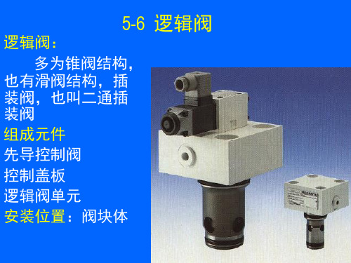
逻辑阀工作原理
逻辑阀是一种控制装置,其工作原理基于逻辑电路的原理。
它用于控制电路的通断状态,根据输入信号的逻辑关系来判断输出信号的开闭状态。
逻辑阀通常由逻辑门电路组成,常见的逻辑门有与门、或门、非门等。
每个逻辑门有指定的输入和输出端口,在输入端口接收信号,在输出端口产生相应的输出信号。
不同逻辑门的工作原理略有差异,但基本思想是一致的。
以与门为例,它有两个输入端口和一个输出端口。
当两个输入信号同时为高电平(1)时,输出信号才会为高电平;否则,
输出信号为低电平(0)。
这种逻辑关系使得与门可以用于判
断多个输入信号的逻辑关系,根据结果来控制输出信号的状态。
逻辑阀的工作原理可以简单总结为以下几个步骤:
1. 接收输入信号:逻辑阀会接收输入信号,根据预设的逻辑关系进行处理。
2. 判断逻辑关系:逻辑阀会根据输入信号的逻辑关系来判定输出信号的状态。
3. 控制输出信号:根据判断结果,逻辑阀会产生相应的输出信号,控制电路的通断状态。
逻辑阀常用于数字电路中,例如计算机和其他电子设备的逻辑控制电路。
它可以实现各种逻辑功能,如逻辑运算、数据处理等。
通过合理组合逻辑阀,可以实现复杂的逻辑处理,满足不同应用的需求。
总的来说,逻辑阀的工作原理是基于逻辑电路的,通过处理输入信号的逻辑关系,判定输出信号的状态,并控制电路的通断。
这种原理使得逻辑阀成为数字电路中不可或缺的控制装置。
![知识点五 逻辑阀与组合阀_气动与液压技术基本功_[共3页]](https://img.taocdn.com/s1/m/68a60f0b5022aaea998f0fe8.png)
81 需要进行压力控制和保护的设备或场合,如空压机的最高压力和最低压力保护等。
如图4-50所示,触点1、2、4共同构成两对触点:1、2是常闭触点,1、4为常开触点,当X 口的气压达到最高值时,即可推动阀芯克服弹簧阻力而右移,使触点1、2断开,1、4闭合而导通;当X 处的压力下降到最低值时,阀芯在弹簧力的作用下左移,电气触点复位:1、2闭合,1
、
4断开。
压力范围通过调节旋钮来设定。
这种利用气信号来接通和断开电路的装置也叫气—电转换器。
图4-49 溢流阀与顺序阀
(a )压力开关工作原理图 (b )压力开关实物图 图4-50 压力开关
知识点五 逻辑阀与组合阀
一、逻辑阀
在气动系统中,如果气缸的动作是由多个输入信号来控制,那么就要通过由逻辑元件构成的逻辑回路来处理这些信号间的关系,实现执行元件的要求动作。
1.或阀——梭阀
如图4-51所示,两个输入口10和11具有单向阀的特性,输出口为2。
如果气体从10流入,阀会将另一个11封住,气体从10口流入2口。
如果气体从11流入,阀会将另一个10封住,气体从11口流入2口,即有一个输入就有输出“或”。
如果气缸或阀排气时,梭阀保持当时的状态。
2.与阀——双压阀
如图4-52所示,两个输入口10和11同时有气体流入,输出口2才有气体输出,即必须同时两个都有输入才有输出“与”。
双压阀主要用于互锁控制、安全控制和逻辑功能。
3.快排阀
快排阀可以提高气缸的运动速度,降低气缸回程时间,尤其是对单作用气缸。
快排的道。


DKJ型电动执行器的工作原理及调试方法摘要:主要介绍了DKJ电动执行器的工作原理及基本结构特点,现场调校以及在实际应用当中所遇到的一些技术问题以及解决的办法,在此都做了详细阐述。
前言DKJ型电动执行器在电厂的应用广泛,而因执行器引发的故障占日常维修工作中所占的比例非常高,就需要一些能掌握执行器维修的方式方法,我在几年的实践工作中通过自己的努力学习和探讨,终于掌握了一些维修技术,现在就把DKJ型电动执行器的工作原理及调试方法做一下简单介绍。
一、电动执行器的基本结构及其工作原理电动执行器是DDZ-Ⅲ型电动单元组合仪表中的执行单元。
它是以两相伺服电动机为动力的,接受调节器或操作器发送来的4-20mA 直流电信号,将其线性地转换成0°~90°的机械转角,用以操纵风门、挡板、阀门等调节机构,实现自动调节。
1、电动执行器的基本结构它是由伺服放大器和执行器两大部分组成。
伺服放大器又由电源、前置磁放大器、触发器主回路和校正回路组成。
执行器又包括伺服电动机、减速器和位置发送器等。
2、电动执行器的工作原理当电动操作器没动作时,伺服放大器的输放端无输入信号(即Ii=0)时,伺服放器没有输出,两相伺服电机不会转动,输出轴稳定在预先选好的零位上。
这时位置发送器的输出电流也为零位。
当电动操作器开大时,使伺服放大器的输入端有直流电信号Ii产生,再经过伺服放大器中的前置磁放大器对信号Ii与反馈信号If进行比较,放大的综合作用后产生生正偏差电信号I(其中I=Ii-I f﹥0),使触发器产生脉冲,导通相应的主回路,接通~220V电源,驱动伺服电机正转,经机械减速后,使输出轴转角θ(0°~90°)线性地转换成负反馈电流信号If(4~20mA)反馈到伺服放大器的输入端用以平衡输入信号,直至If≌Ii重新使偏差信号ΔI=0时,伺服电机才停止转动,输出轴停留在某一新的位置。
反之,当操作器开小时,伺服放大器的输入端输入信号也减小,再经过前置磁放大器的综合处理后,产生负偏差信号ΔI=0,这时会使另一个主回路导通,两相伺服电机反转,办理出轴转角θ减小,挡板或阀门承受之关小。
Solenoid directional valves type DKEdirect operated, ISO 4401 size 10Table E025-7/ESpool type, direct operated valves with threaded solenoids certified according the North American standard cURusSingle and double solenoid valves are available in two or three position configurations and with a wide range of interchangeable spools ቢwith different schemes, three or four way connections,see section ݘ.Solenoids ባare made by:• wet type screwed tube, different for AC and DC power supply, with integrated manual override pin ቤ• interchangeable coils, specific for AC or DC power supply, easily replaceable without tools - see section ݛfor available voltagesStandard coils protection IP65(once correctly assembled with relevant electric connectors).The coils are insulated according to class H for DC and F for AC versions.The valve body ቤis 5 chamber type for all DC versions and for AC safety version /FI and FVStandard AC version uses 3 chamber type bodyThe body is made by shell-moulding casting with wide internal passages ensuring low pressure dropsOptions• prolonged manual override protected with rubber cap ቦfor easy hand operation• control devices of the valve switching time• spool position monitor devices for safety applications• optional IP67AMP Junior Timer and Deutsch coil’s connectors or lead wire for customized applications Surface mounting ISO 4401 size 10Max flow up to 150 l/min Max pressure: 350 barDKE – 1Valve configuration, see section ݘ61=single solenoid, center plus external position,spring centered63=single solenoid, 2 external positions, spring offset 67=single solenoid, center plus external position,spring offset70=double solenoid, 2 external positions, withoutsprings71=double solenoid, 3 positions, spring centered 75=double solenoid, 2 external positions, with detent Other configurations are available on request.Spool type, see section ݘSeries number/A **63/*1MODEL CODEE0251/2Options, see note 1 at section ݚX 24 DC Voltage code, see section ݛ-00-AC =AC solenoids without coils 00-DC = DC solenoids without coils X = without connectorSee note 2 at section ݚ for available connectors,to be ordered separatelyCoils with special connectors, see section ݜXJ = AMP junior Timer connector XK = Deutsch connector XS = Lead Wire connectionDirectional control valves ISO 4401 size 10Seals material:omit for NBR (mineral oil & water glycol)PE = FPM2CONFIGURATIONS and SPOOLS (representation according to ISO 1219-1)3MAIN CHARACTERISTICS OF DKE DIRECTIONAL VALVES(1)In case of 60 Hz voltage fre-quency the performances arereduced by 10÷15% and thepower consumption is 80 VA(2)Average values based on testsperformed at nominal hydrau-lic condition and ambient/coiltemperature of 20°C.(3)When solenoid is energized,the inrush current is approx 3times the holding current.Inrush current values corre-spond to a power consumptionof about 280 VA6COILS TYPE CAE WITH SPECIAL CONNECTORS (only for 12DC, 14DC, 24DC and 28DC)Options -XJCoil type CAEJAMP Junior Timer connectorProtection degree IP67Options -XKCoil type CAEKDeutsch connector, DT-04-2P maleProtection degree IP67Options -XSCoil type CAESLead Wire connection5ELECTRIC FEATURES666or66766936 W85 VA(3)36 WExternal supplynominal voltage± 10%Type ofconnectorPowerconsumption(2)Code of spare coilVoltage code12 DC14 DC24 DC28 DC110 DC220 DC110/50/60 AC230/50/60 AC115/60 AC230/60 AC110/50/60 AC230/50/60 AC12 DC14 DC24 DC28 DC110 DC220 DC110/50/60 AC230/50/60 AC115/60 AC230/60 AC110 DC220 DCCAE-12DCCAE-14DCCAE-24DCCAE-28DCCAE-110DCCAE-220DCCAE-110/50/60AC (1)CAE-230/50/60AC (1)CAE-115/60ACCAE-230/60ACCAE-110DCCAE-220DC4NOTES1OptionsA= Solenoid mounted at side of port B (only for single solenoid valves). In standard versions, solenoid is mounted at side of port A.WP = prolonged manual override protected by rubber cap - see sectionWPD/KE-DC = (only for DC supply) manual override with detent, to be ordered separately, see tab. K150L, L1, L2, L3, LR, L7, L8see section = device for switching time control (only for DC solenoids).L7 and L8 are available only for spool type 0/1, 1/1, 3/1, 4 and 5.FI, FV = 5 chambers body for DC and AC versions with proximity switch for spool position monitoring: see tab. E110.Y = external drain, only for DC version,to be selected if the pressure at T port is higher than the max allowed limits.2 Type of electric connectors DIN 43650, to be ordered separately - see section .666=standard connector IP-65 for direct connection to electric supply source.667=as 666, but with built-in signal led.669=with built-in rectifier bridge for supplying DC coils by alternate current (AC 110V and 230V - Imax 1A).3 Spools- spools type 0and 3are also available as 0/1and 3/1with restricted oil passages in central position, from user ports to tank.-spools type 1is also available as 1/1, properly shaped to reduce the water-hammer shocks during the switching.- spool type 1/9has closed center in rest position but it avoids the pressurization of A and B ports due to the internal leakages.- other types of spools can be supplied on request.131211Assembly position / location Any position for all valves except for type - 170* (without springs) that must be installed with horizontalaxis if operated by impulsesSubplate surface finishing Roughness index Ra 0,4 - flatness ratio 0,01/100 (ISO 1101)MTTFd values according to EN ISO 13849300 years, for further details see technical table P007Ambient temperature from -30°C to +70°C (standard seals) -20°C to +70°C (/PE seals)Fluid Hydraulic oil as per DIN 51524 .... 535; for other fluids see section ݗRecommended viscosity15 ÷ 100 mm2/s (ISO VG 15 ÷ 100) may allowed 2,8 ÷ 500 mm2/sFluid contamination class ISO 4406 class 21/19/16 NAS 1638 class 10, in line filters of 25 μm (β25 _>75 recommended)Fluid temperature-30°C +60°C (standard seals) -20°C +80°C (/PE seals)Flow direction As shown in the symbols of table ݘOperating pressureRated flow See diagrams Q/Δp at section ݝMaximum flow150 l/min, see operating limits at section ݞPorts P,A,B: 350bar;Port T 210bar for DC version (250bar with option /Y); 160bar for AC version3.1 Coils characteristicsInsulation classH(180°C) for DC coils F(155°C) for AC coilsDue to the occuring surface temperatures of the solenoid coils, the European standards EN ISO 13732-1and EN ISO 4413 must be taken into accountProtection degree to DIN EN 60529IP 65 (with connectors 666, 667, 669 correctly assembled)Relative duty factor100%Supply voltage and frequency See electric feature ݛSupply voltage tolerance± 10%Certification C UR US North American Standard25507510012515060120180240300360E0257Q/ΔP DIAGRAMS based on mineral oil ISO VG 46 at 50°C11DEVICES FOR SWITCHING TIME CONTROL0, 0/1, 0/2, 2/2A A B B 1, 1/1, 1/9, 6, 8A A D C 3, 3/1, 7A A C D 4B B B B F 5, 58A B C C G1/2B C C B 19, 91F F G G H 39, 93FFGGH Flow directionSpool type P →A P →B A →T B →T P →T B →A9SWITCHING TIMES (average values in msec)DKE + 666 / 66740602535DKE + 66960––90––DK -*/L* ––75÷150––45÷150DKE-*/L7 - DKE-*/L8––100÷150––100÷150ValveSwitch-onSwitch-on Switch-off Switch-off ACDCAC DCTest conditions:- 50 l/min; 150 bar- nominal supply voltage- 2 bar of back pressure on port T - mineral oil ISO VG 46 at 50°CThe elasticity of the hydraulic circuit and the variations of the hydraulic characteristics and temperature affect the response time.ValveAC DC (cycles/h)(cycles/h)0255075100125150369121518DKEV a l v e p r e s s u r e d r o p Δp [b a r ]Flow rate [l/min]G F E D C B AH 8OPERATING LIMITS based on mineral oil ISO VG 46 at 50°CThe diagrams have been obtained with warm solenoids and power supply at lowest value (V nom - 10%). The curves refer to application with symmetrical flow through the valve (i.e. P →A and B →T). In case of asymmetric flow and if the valves have the devices for controlling the switching times the operating limits must be reduced.A 0/10, 0/1, 1, 1/1, 3, 3/1, 1/2, 0/2, 8B 4, 5, 19, 916, 7C 0, 1/1, 3, 3/119, 91D 1, 1/2, 0/24, 5E 6, 7, 8, 2/22/2U -4, 5Z-0/1, 1/1, 3/1CurveSpool typeACDC10SWITCHING FREQUENCY025507510012515060120180240300360I n l e t p r e s s u r e [b a r ]Flow rate [l/min]DKE - DC / options L7, L8U ZThese devices are only available for DC valve version (5 chambers body) and can control the swit-ching time and therefore reduce the coil hammering in the hydraulic circuit. The different types are available shown in the figure.- L :controls and regulates the switching time in both moving directions of the spool: regulation iscarried out by screwing/unscrewing the element itself (regulating choke);- L1/L2/L3: controls the switching time in both moving directions of the spool by means of fixedcalibrated restrictor (gauged flow). The restrictor is positioned in the valve’s body ØL1 = 1,25 mm; ØL2 = 1 mm; ØL3 = 0,75 mm;- LR :controls and regulates the switching time in the B →A direction of the spool movement. Thedevice does not control the switching time (standard time) in the opposite direction A →B of the spool movement.- L7/L8: controls the switching time in both moving directions of the spool by means of fixed cali-brated restrictor (gauged flow). The restrictor is installed in the solenoid’s anchor.For a correct operation of the switching time control, the passage in which the control device is installed must be completely filled with oil.DKE + 666 / 667720015000025507510012515060120180240300360Flow rate [l/min]I n l e t p r e s s u r e [b a r ]C I n l e t p r e s s u r e [b a r ]Flow rate [l/min]DKE - DCDKE - ACAE DCBABED12INSTALLATION DIMENSIONS [mm]05/1414MOUNTING SUBPLATESModel Ports locationGAS PortsA-B-P-T (X-Y)ØCounterbore[mm]A-B-P-T (X-Y)Mass[kg] BA-308(/Y)BA-428(/Y)BA-434(/Y)Ports A, B, P, T (X, Y) underneathPorts A, B, P, T (X, Y) underneathPorts P, T, (X, Y) underneath; ports A, B on lateral side1/2" (1/4")3/4" (1/4")3/4" (1/4")30 (21,5)36,5 (21,5)36,5 (21,5)2,55,58,5 The subplates are supplied with 4 fastening bolts M6x40. Also available are multi-station subplates and modular subplates. For further details see table K280.。
一.电动系列1 电动执行器注:红色部分为引申的下一层角行程电动执行器(配角行程图片(1),加配套文字;配图片角行程DKJ系列(1))直行程电动执行器(配图片直行程电动执行器(1)配文字)多转式电动执行器(配图片多转式电动执行器(1),配文字)2电子式单座双座调节阀(配电动调节阀图片(2),以及文字)3电动蝶阀电动蝶阀(配图片电动蝶阀(3))电动风阀(配图片电动风阀(3))4电动百叶式矩形风阀(配矩形风阀(4)及文字)二.气动系列1气动执行器(配图片气动执行器(5)(6))2气动阀门气动调节阀(配图片气动调节阀(7))气动球阀(配图片气动球阀(7))三.相关配套仪表球型铰链(配图片(8))操作器(配图(9))伺服放大器文字说明1角行程电动执行器S D系列智能型电动执行机构是本公司引进法国技术生产的具有世界先进水平的产品, 其主要部件均为进口,产品严格执行国家标准。
目前生产的SD系列包括角行程、直行程、多转式三大类包括调节型、远控型、开关型等,SD系列智能电动执行机构功能齐全,质量稳定,安全可靠,精度高、规格多、重量轻、安装调试灵活方便,广泛应用于电力、冶金、石化、建材、供热、轻工、水处理、脱硫等行业,在工业过程控制系统中发挥着重要作用。
SD系列电动执行机构是自动调节系统的终端控制装置,它接收来自DCS系统调节器或计算机的4~20mA(或1~5V)模拟量信号及断续接点控制信号,输出力矩或力,自动地操纵调节机构,完成自动调节任务。
它也可以通过操作器实现“手动—自动”转换,切换到手动时,用操作器可对执行机构进行远方控制。
角行程电动执行机构,可用于控制各类转角90°的阀门如:蝶阀、球阀、百叶阀、风门、旋塞阀、挡板阀等。
直行程电动执行机构是输出直线位移的电动执行机构,可用于控制各种需要直线位移的调节阀,如单、双座调节阀、套筒阀、高温高压给水阀、隔膜阀、减温水等调节阀。
产品的种类及型式1、SD系列电动执行机构输出方式分成三种:A.角行程—输出0~90°角位移的力矩。
常关, 平衡提动塞, 导压开逻辑元件
容量: 120 GPM (480 LPM)
型号:
DKJC
产品说明
常关, 平衡提动塞, 可调元件. 口3导压切换阀至开启位置.
技术特点
独特平衡设计提供预测切换压5000 psi (350 bar) 于口1 及口2, 单独回油箱开以及最小导压 300 psi (20 bar). 于5000 psi (350 bar)压力下, 口1及口2 之间漏损率小于每分钟5滴.
当导压降低于145 psi (10 bar) 时, 阀将重设.可保持口1及口2中间液压平衡.
口1及口2与口3完全密封
3口平衡逻辑阀使用的插孔, 尺寸与非平衡逻辑阀相同, 并可提供替换用的相同功能.
可选择透大气 (X控制) 或者静态单独回油箱(E 控制) 设定选项.
包含Sun的独特浮动式设计可消除因多余的安装力矩以及/或插孔/插式阀机械性的差异所产生的内部黏合.
3口透气逻辑元件附X控制为参照大气并可解不透气阀的现有油路问题. 但随着时间, 阀将
因外漏损让湿气进入弹簧膛. 因此建议使用4
口阀于新型的应用. 或者使用静态回油箱口选项 (E控制) 连接外透气口于油箱口. 移除透
气口封盖将转换X控制至E控制.
技术数据
英制公制
重量- -
插孔T-19A 阀型4
容量120 gpm480 L/min.最大操作压力5000 psi350 bar
最大漏损于110 SUS (24 cSt) 5 drops/min.0,4 cc/min.阀切换所需最低导压压力300 psi20 bar
导压容积排量0.05 in³0,82 cc
六角头尺寸 1 1/4 in.31,8 mm 安装力矩150 - 160 lbf ft200 - 215 Nm 密封包Buna: 990-017-007
密封包Viton: 990-017-006
标称重量 1.32 lb0.60 kg
型号
DKJC -E H N
选购规格
控制方式最小导压压力油封类型标准选项
E单独回油箱 4-SAE+0.00 X标准导压, 透大气+4.00H 200 psi (14 bar)+0.00N Buna-N +0.00
V Viton +5.00
*如需特殊设定, 订购时请详细说明.
Copyright © 2005-2006 Sun Hydraulics Corporation.
All rights reserved.
Terms and Conditions - Statement of Privacy。