PACI系列三相电力调整器
- 格式:pdf
- 大小:2.07 MB
- 文档页数:9
![三相晶闸管调整器PAC36P系列使用说明书[1]](https://uimg.taocdn.com/57bc134de45c3b3567ec8bde.webp)

PAC30A+系列智能型SCR调功调压器说明书PAC30A+系列智能型SCR调功调压器PAC30A+系列SCR调功调压器是大功率可控硅模块应用技术的新产品。
它集三相调压/调功方式为一体,具有自动判别相位、上电缓启动、缓关断、散热器超温等功能,适用于电阻性负载和感性负载。
一.产品特点本公司自主研发生产的PAC30A+系列SCR调功调压器是集合我公司多年电加热控制经验,是专为电炉设备而设计的:其调功、调压、负载中心接地、不接地,可以由客户任意设置的一款产品,从而达到了真正的智能化。
其调压(移相导通)调功(过零导通)功能的转换只需要拨一下拨码开关即可实现,非常简单,并且,调功还具有周波功能,避免电流表指针来回摆动。
此调功/调压的功能转换,主要是多台运行时,移相导通对电网有干扰,使功率因数下降,因此,必须转换成节能环保的调功模式。
其散热风冷单元采用特殊设计的插片式散热器,比普通铝型材散热器散热效率提高了30%,更利于模块的散热,从而极大的提高了模块的使用寿命。
同时,还具有模块超温报警功能,便于及时了解模块的工作状态。
本产品结构合理,保护功能完善,规格齐全,有30A 至400A的电流容量机型可供用户选择。
该产品可广泛适用于工业热处理、电热加工、材料制造、航天航空、冶金、有色、医药、电子、食品机械、注塑机械、喷涂机械、真空镀膜机等各种设备上。
二.技术规格三. 安装及使用须知●使用前请认真阅读本说明书,严格按要求接线使用。
●本电压调整器是壁挂式,垂直安装在通风良好,不受日光直射或热辐射,无腐蚀性、无可燃性的环境中。
●负载应无短路、局部放电打火等现象,要求绝缘良好。
●特别指出:变压器负载不能空载或轻载运行。
●散热器超温保护后,如要运行,需排除故障后,再送电运行。
四. 装箱清单表PAC30A 整机一台,10K 电位器一只,说明书1 份。
降额2-3倍使用B300S-250A 350m m×244m m×265mm MTC-300A ≤164KW B350S-320A 450m m×244m m×270mm MTC-500A ≤210KW B400S-400A 463m m×304m m×300mm MTC-600A ≤260KW B400S-600A-2 463m m×304m m×300mm MTC-800A ≤395KW六.订货说明1.SCR调功调压器电流容量选择参考●一般纯阻负载:电力调整器电流容量应大于负载最大电流。
单相一体化电力调整器Integration of Single-phasepower regulator PAC16P使用说明书OPERATING INSTRUCTIONSPAC16P产品概述它集单相调压/调功方式为一体。
具有上电缓启动、缓关断、散热器超温、电流限制、过流保护,适用于电阻性负载和感性负载,可广泛用于工业领域的功率调整。
订货说明1.电力调整器电流容量选择参考● 一般纯阻负载:电力调整器电流容量应大于负载最大电流。
● 硅碳棒负载:当取消变压器时,硅碳棒应串联,使之能够承受电源电压的70%~80%以上。
硅碳棒在700~800℃存在负阻区,电力调整器电流容量应大于负载最大电流的1.7倍。
● 电热管负载:电热管易受潮、局部短路和放电打火等,电力调整器电流容量应大于负载最大电流的1.7倍。
● 变压器负载:应带电流限制功能,电流容量应大于负载最大电流的2~2.5倍。
● 特殊负载应加大电流容量,订货时声明。
一.型号定义 (4)二.产品系列 (4)三.主要技术参数 (4)四.LED状态灯显示及拨码开关SW1工作方式定义 (5)五.配线及应用 (5)5.1PAC16P基本运行与电压限制、手动、报警输出、调压调功接线图 (6)5.2各种接线方式组合 (6)5.3过流保护选件接线、调试与应用说明 (7)5.4U1选件功能及调压调功一体化技术 (8)六.初步调试及故障排除 (9)七.尺寸图 (10).型号定义一五.配线及应用步骤一:自动调试:将仪表4~20mA的输出信号接到C1、C2端,R1、R2短路,按上图的自动控制接线。
输入变化信号逐步增大时,绿色输入灯亮度和负载电压应随输入增加。
步骤二:手动调整:外接10KΩ手动电位器。
电位器的两个固定端分别接V0、GND端,滑动端接R1端,按上图的手动控制接线。
调整手动电位器,负载电压调整范围为0~100%。
此时,负载电压应均匀变化。
步骤三:上电缓启动时间:调整控制板上的P3电位器,启动时间0.2~120秒用户可设。

欧式风格三相电压调整器Continental style three-phasevoltage regulatorPAC30A 使用说明书OPERATINGINSTRUCTIONS希曼顿电子科技有限公司X imandun Electronic Technology Co., LtdXIMANDUN简介希曼顿电子科技有限公司,创立于1985年,是以设计开发、生产、销售全系列工业级交流固态继电器(SSR)、一体化电力调整器为主的高新技术企业,并荣获超大功率SSR、全数字化SSR控制器和柔性导热垫片等多项国家专利。
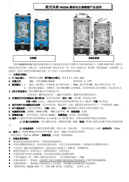
PAC30A产品概述全新PAC30A智能三相调压器以令人惊叹的完美设计开创数字式调压器的新纪元。
它操作和维护简单,独立的三只电力模块,易于散热和维护,并避免了危险集中。
欧式风格的安全防尘结构,美观大方。
红绿蓝色LED灯,工作状态一目了然。
CS插片式散热器比普通散热器的散热效率高30%~100%。
其它功能还包括:手动/自动,最大电压限制,自动判相,缺相保护,上电缓启动、缓关断、散热器超温,CS的霍尔转速检测接口,可广泛用于工业各领域中的阻性或感性负载。
订货说明1.电力调整器电流容量选择参考● 一般纯阻负载:电力调整器电流容量应大于负载最大电流。
● 硅碳棒负载:当取消变压器时,硅碳棒应串联,使之能够承受电源电压的70%~80%以上。
硅碳棒在700~800℃存在负阻区,电力调整器电流容量应大于负载最大电流的1.7倍。
● 电热管负载:电热管易受潮、局部短路和放电打火等,电力调整器电流容量应大于负载最大电流的1.7倍。
● 变压器负载:应带电流限制功能,电流容量应大于负载最大电流的2~2.5倍。
● 特殊负载应加大电流容量,订货时声明。
2.定货例:PAC30A-YT-150含义如下欧式风格三相电力调整器,负载接线方式为外三角形或中心不接地,纯组负载电流最大值为150A目录一.型号定义 (4)二.产品系列 (4)三.主要技术指标 (4)四.LED灯状态显示 (5)五.接线及应用 (5)六.初始调试 (6)七.常见故障及处理与保养维护 (7)八.尺寸图 (8)一.型号定义图1-1:负载电流150安培以下型号定义图1-2:电流150~600A 带霍尔风机型号定义注:PAC30A--40一般为自然冷却如需风冷,请订货时说明,尺寸与PAC30A--60相同四.LED灯状态显示五.接线及应用图1-3:全部功能实现接线及原理图图1-4:三相四线YN接线图各种功能接线实现组合六.初始调试为调试可靠、顺利进行,一般先接假负载(如:100~200W灯泡、电炉等)。
目录安全及注意事项 (I)第一章H系列三相功率控制器的作用及特点 (1)1.1 作用 (1)1.2 特点 (1)第二章产品信息 (3)2.1 型号定义 (3)2.2 铭牌 (3)2.3 产品规格 (4)2.4 技术参数 (4)2.5 缩略语 (5)第三章安装及配线 (6)3.1 开箱检查 (6)3.2 使用条件 (6)3.3 安装 (7)3.4 电气配线 (7)3.5 基本接线原理图 (8)3.6 端子说明 (9)第四章显示及操作说明 (10)4.1 监控界面显示信息说明 (11)4.2 按键功能说明 (11)4.3 操作举例说明 (12)4.4 菜单 (12)4.5 控制参数A (13)4.6 显示参数B (13)4.7 保护参数C (13)4.7 保护参数C (14)4.8 高级参数D (14)第五章功率控制器功能介绍 (15)5.1 功能介绍 (15)5.2 功能参数表 (22)5.3 参数说明 (23)5.4 举例说明 (32)第六章故障处理及保养维护 (35)6.1 故障处理 (35)6.2 保养维护 (35)第七章通信说明 (37)7.1 通讯数据读写 (37)7.2 协议内容 (37)7.3 总线结构 (37)7.4 通讯帧结构 (38)7.5 MODBUS通讯协议 (38)第八章售后服务 (40)附表一 (41)I安全及注意事项危险:由于没有按要求操作,可能造成设备严重损坏或人员伤亡的场合。
注意:由于没有按要求操作可能造成中等程度伤害或轻伤,或造成物质损失的场合。
本指示对于正在工作的功率控制器非常重要,忽略这些指示可能对您造成身体损害甚至导致死亡。
○1安装控制器应安装在金属等不可燃物上,否则有发生火灾的危险。
不要安装在含有爆炸性气体的环境里,否则有引发火灾的危险。
不要把易燃、易爆物品放在控制器附近,否则有引发爆炸的危险。
不要将螺钉、垫片等金属物掉进控制器内部,否则有引发爆炸和发生火灾的危险。


选型表单相调压器负载电源220VAC 恒阻负载电流80A 加热器断线报警,无特殊调功★负载电源和同步电压:调压工作方式时,负载电源和同步电压必须同相位.一. PAC01A主要技术指标:1.4~20mA输入: 接收阻抗500Ω~1.5K;调压分辨力: 0.1% 。
2.负载电源: 50Hz 单相110VAC/220VAC/380VAC 移相范围:0~170°3. 同步电源:110VAC/220VAC/380VAC,见标牌4. 外部电压调整: 10K带刻度盘电位器调整范围 0~100% 。
5.缓启、缓停: 起停开关控制缓启动、缓停时间均固定为15秒。
无起停开关控制时,第一次上电自动缓启动。
6.80℃超温保护:散热器温度大于80℃±3℃禁止输出并报警解除:故障排除后,重新上电。
7.电流容量: 40A 、 60A 、 80A 、 120A 、150A AC8. 报警输出: 光电隔离OC门输出,隔离电压1500V (5~24VDC的外供电源)。
二.三. 安装及使用须知:● 使用前请认真阅读本说明书,严格按要求接线使用。
● 本电压调整器需垂直安装在通风良好,不受日光直射或热辐射,无腐蚀性无可燃性的环境中。
● 工作电流 >30A,需采用强制风冷。
高温高湿以及海拔大于1000米,应降额使用。
● 装置过热保护后,如要再运行,需排除故障后,再送电运行。
● 工作环境温度:-10℃~+55℃ 通风良好的位置。
工作环境相对湿度: 90%。
● 负载短路保护:一般按额定负载电流的1.5倍选择,外配RS0快速熔断器作为短路保护。
● 感性负载必须使用外部起停开关和加热器断线报警HB 功能(选件) 四. 初步调试1. 初始接线:参照最简接线图接线,为调试可靠,一般先接100~200W 灯泡假负载并将仪表置手动状态。
手动电压输出范围为0~100%。
此时,负载电压应均匀变化。
仪表无手动,输入20mA ,可利用外部电压调整电位器重复试验。
三相晶闸管调功器PAC36P 系列使用说明书 1. 检查规格 PAC36P 代码型号代码价格 PAC36P -相位控制3 1~5V DC 输入阻抗200K Ω4 4~20mA DC 接受阻抗100Ω 6 0~10V DC 输入阻抗100Ω控制输入9 其他另加 15 200~220V 16 220~240V 17 380~400V电源电压18 400~440V200~240V /电流容量380~440V / 电流容量 02120 A022 20 A 03130 A 032 30 A 04145 A 042 45 A 06160 A 062 60 A 09190 A 092 90 A 131135 A 132 135 A181180 A 182 180 A 241240 A 242 240 A 301300 A 302 300 A 451450 A 452 450 A 电流容量601600 A 602 600 A0 恒电压 1 恒电流2 恒功率 反馈功能3 电压平方根0 无1 启动输出限制(0~60%,1~60s )2 电流限制输出控制功能3 启动输出限制 + 电流限制N 无P 外部功率调节 M 手动调节B 下限功率调节W 外部功率调节 + 手动调节 电流 / 电压输入Y 外部功率调节 + 下限功率调节 P 外部功率调节外部功率调节接点输入H 上 / 下限功率调节0无加热器断线报警1有(0~100%)0无快熔1有0无44~20mA DC 接受阻抗:100Ω自动功率调节功能 60~10V DC 输入阻抗:200K Ω0无特殊要求9请订货前说明2. 面板与控制端子 2.1 面板•调节旋钮内置功率调节(标配) 软启动时间调节(标配) 加热器断线报警设置(选件) 自动功率调节(选件) •指示灯 P.L 电源与输出指示灯绿色——相序正确红色——相序错误或开路O.C 过流(选件) FUSE 快熔熔断(选件) H/B 加热器断线报警(选件) FAN 风扇停转(180A 以上标配) •端子代码与功能 C1,C2: 输入R1,R2,R3: 外部功率调节?(选件) M :手动/下限调节(选件) AL1,AL2,AL3:报警输出公共端到过流、风扇及快熔S1,S2:软启动外部同步信号输入 CL1,CL2,CL3:电流限制调节电位器接线端 AP1,AP2: 自动功率调节信号输入RB1,RB2:加热器断线报警输出2.2 控制端子有20个端子分上下两层。
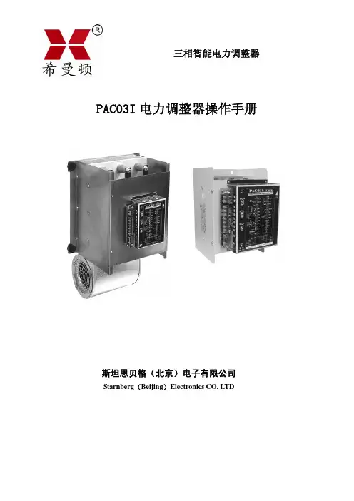
智能交流电力控制器是中日合作超大功率固态继电器应用技术的新概念产品。
它包括三相调压/调功一体化PAC03I 、工业DCS 周波过零控制器ZAC10及后续系列。
额定电流40~500A ,带锁相环同步电路、自动判别相位、缺相保护、上电缓启动、缓关断、散热器超温、快熔检测、电流限制、电压反馈、过流保护、串行工作状态指示、串行遥控操作器、PAC03IA 还能与上位机通信,实现系统集成。
智能交流电力控制器可广泛用于工业各领域的电压调节,恒压,恒流,恒功率调节,适用于电阻性负载、电感性负载、变压器和电机软起控制等。
一. PAC03I 主要技术指标:4~20mA 输入: 接收阻抗120Ω 调节输出分辨力:0.2°,三相触发不平衡度:不大于0.6° 负载方式: PAC03I 50Hz 三相380VAC 三角形或星形中心不接地。
移相范围:0~150°50Hz 三相380VAC 星形中心接地(220V 负载) 移相范围:0~175° 50Hz 三相380VAC 半控整流桥。
移相范围:0~175°隔离驱动输出:8V 峰值脉冲,8°~ 120°可变脉宽,每路可2串2并接4支同相SSR 。
最大驱动电流:< 30 mA 纯阻电流等级:60A 、90A 、120A 、180A 、250A 、300A 散热单元:B160、B227、B301A 、B361、B401配置见选型表 五只LED 灯状态显示:红绿黄LED 三相电源指示和快熔断路指示;绿色INPUT 输入信号线性指示灯。
三色状态灯: RUN 绿色运行灯;ALM 红色报警灯;STOP 黄色闪烁的待机灯。
外部执行开关的缓起动,缓关断: 无电压接点输入 闭合(ON ):缓关断,时间固定3秒;开路(OFF ): 由内部电位器P3设定0.2~120秒缓起动时间 不接:直接运行 运行过程中自动缓起动及急停: 运行过程中瞬间缺相急停,加电后自动缓起动(三缺一相方式时被取消)。
■Wide application with variety of functions20~600A■Suitable for air conditioning, electric, furnace, dryer,bio engineering, food industry, chemical industry,plastic formation and control of heat source applications.FUNCTIONStandard FunctionElectronic over current protect function:Protects thyristor element by shutting off the over current detected by a load current monitoring CT.Constant voltage characteristics by means of voltage Stable output provided by the voltage control function and easy operation achieved feedback:by the linear characteristics of control input and output voltage.Soft start function:Setting suitable soft start time for the load.Monitor and Alarm Output on the Trouble SituationAdditional Function (option)Automatic power adjusting function:The suitable power for the control temperature is continuously controlled by a signal from the programmable controller, computer and adjuster. Applicable for soft control of the low range.Constant-current control (Current feedback):Applicable to controlling the pure metallic heater and the Kanthal Super heater.Constant-power control (Power feedback):Applicable to controlling the SiC and the carbon heater, and applicable to high stability controlling.Power linear control (Voltage square feedback):Applicable to precise controlling for Nichrome heater load with power linear characteristics of the control input / output voltage.Current limiting funcion: Applicable to loads with rush current on starting and continuous usage over currentcondition such as pure metallic, Tungsten and Molybdenum heaters.Start up output limiting function:Applicable to the rush current reduction and load protection on turning on the power supply.Heater break alarm:Alarm display and output in case of detecting the low power condition of the broken heater and heater defect.Power adjustment function:Addition of various manual equipment used for adjusting ramp, base (residual output), manual and high / low.Rapid fuse:P of the short circuit and the grounding.erfect protection for the thyristor device and the power line from the over current SERIESPAC36P 240A, 300A20A 30A, 45A 60A, 90A 135A, 180A 450A, 600AStable output provided by the voltage control function and easy operation achievedOver-current protection:[O.C] monitor lights and alarm output on Fan stop (for models over 180A):[FAN] monitor lights and alarm output on Rapid fuse burnt out:[FUSE] monitor lights and alarm output on Heater break alarm:[H / B] monitor lights and warning output onSPECIFICATIONINTERNAL HEAT GENERATEDControl input and Rating Current input:4~20mA / DC, Receiving impedance:100ΩVoltage input:1~5V / DC, Input impedance: 200k Ω min.0~10V / DC, Input impedance: 200k Ω min.Contact signal:Non-volatage contact signal Note: Select external power (P) or (H) in the table of code Selection Item 7, (Output Adjusting Function)Power Supply and Rating 200V type:200~220V AC ± 10% 50 / 60Hz 220~240V AC ± 10% 50 / 60Hz 400V type:380~400V AC ± 10% 50 / 60Hz 400~440V AC ± 10% 50 / 60Hz Control Mode:Phase angle control system Soft start:Adjustable approx. 1~10 sec. (time for reaching 90%)Applicable load:Resistive load, inductive load (transformer primary side control)Output voltage control range:0~98% minimum of input voltage Output stability (95% or less of output voltage):Input fluctuation ± 2% or less when input fluctuation is ± 10%.Control element configuration:Mixed antiparallel configuration of SCRs and diodesOver-current Protection SystemElectronic type (gate signal breaking system) standard:approx. 130% of rated current Rapid fuse type (optional):130~150% of rated current ResetElectronic type:Turn power OFF and reapply Rapid fuse:Replace fuse.Current Capacity and Cooling System20A,30A,45A,60A,90A,135A:Self-cooling system 180A,240A,300A,450A,600A:Forced air cooling system Alarm Monitors and Rating Over-current:[O.C] monitor lights. / AL1-AL2conductingFan stop:[FAN] monitor lights. / AL1-AL2conductingFuse burnt out:[FUSE] monitor lights./AL1-AL2conductingHeater break:[H / B] monitor lights. / HB1-HB2conductingOutput contact rating:240V AC 1A / Resistive load Power LampCorrect Phase sequence:Green LED lights.sequence:Red LED lights.Open / opposite phase:Operating Environment Ambient temperature range:-10~50˚CAmbient humidity:90% RH max. with no condensationInsulation Resistance Power terminal and chassis:500V DC 20M Ω min.Input terminal and power terminal:500V DC 20M Ω min.Dielectric Strength Power terminals and chassis:200~240V power supply:2000V AC 1 minute 380~440V power supply:2500V AC 1 minuteMaterial / Finish:Ordinary steel plate / paint coating (equivalent to N8.5 Munsell number)External Dimensions and Weight:See external demension drawings.Terminal Cover:Installed as standard equipment.Additional functions (option)Power adjuster Connection tovoltage / current output type controllerInternal Power (standard):0~100%External Power:0~100%Manual Power:0~100%Base Power:0~100%External power + Manual power:0~100%External power + Base power:0~100%Connection to contact output type controller External Power:0~100%High-low power:0~100%Constant-current control (current feedback)Applicable loads:Pure metallic heaters, super Kathal, etc.Constant-power control (power feedback)Applicable loads:SiC, carbon heaters Power linear control (voltage feedback)Applicable loads:Nichrome heaterOutput limiting function:Current limit:50~100% of rated current Start up output limiting:0~60% output for 1~60sec.Rapid fuse:With alarm output function Heater break alarm:Setting at 0~100% of rated current Automatic power adjusting function:50~100%Internal heat generated by series P AC36P at maximum current operation is as follows.The heat decreases is proportional to the current Approx. 10% more heat is generated in case of using rapid fuse.decrease. Ventilation should be considered for the system.Rating current (A)2030456090135180240300450600Internal heat generated (W)82121151196274442620731104015672000ORDERING INFORMATIONITEMSCODESPECIFICATIONSSERIES PAC36PPhase Angle Control 3-Phase Power Regulator 31~5V DC, Input Impedance: 200k Ω / contact signal CONTROL INPUT44~20mA DC, Receiving Impedance: 100Ω / contact signal 60~10V DC, Input Impedance: 200k Ω / contact signal 9Others (Please consult before ordering.)15-200~220V POWER SUPPL Y16-220~240V 17-380~400V 18-400~440V200~240V380~440VCODE CODE 02120A 02220A 03130A 03230A 04145A 04245A CURRENT CAPACITY06160A 06260A 09190A 09290A 131135A 132135A 181180A 182180A 241240A 242240A 301300A 302300A 451450A 452450A 601600A602600AConstant voltage (standard feature)FEEDBACK FUNCTION1Constant current 2Constant power 3Voltage Square-root 0NoneOUTPUT CONTROL FUNCTIONS1Startup time output control limiting (0~60%, 1~60sec.)2Current limiting3Startup time output control + Current limiting WHEN USED N None (Internal installation as standard)WITH VOLTAGEP External power adjuster AND CURRENT M Manual power adjuster EXTERNAL POWER OUTPUT B Base power adjusterADJUSTERCONTROLLER W External power + Manual power Y External power + Base power WHEN USED WITH P External power adjuster CONTACT OUTPUTHHigh-Low power adjuster HEATER BREAK ALARM0Without1With (0~100% setting of rated current)RAPID FUSE0Without1With (See rapid fuse table.)0WithoutAUTO POWER ADJUSTMENT FUNCTIONS44~20mA DC, Receiving Impedance: 100Ω60~10V DC, Input Impedance: 200k ΩREMARKS0Without9With (Please consult before ordering.)CURRENT CAPACITY FUSE CAPACITYPARTS NO.20A 30APower characteristiccontrol signalCR6L- 30S 30A 40A 50SHA 40S 45A 60A 50SHA 60S 60A 100A 50SHB 100S 90A 120A 50SHB 120S 135A 200A CS5F 200180A 250A CS5F 250240A 350A CS5F 350300A 450A CS5F 450450A 600A CS5F 600600A800ACS5F 800DRAWING OF ADDITIONAL FUNCTION CHARACTERISTIC• Automatic Power Adjusting Function• Rapid Fuse Option• Constant Current Characteristics (Current Feedback)• Power Linear Characteristics (Voltage Feedback)• Constant Power Characteristics (Power Feedback)• Current Limiting Characteristics • Start up Output Limiting CharacteristicsHEATER CHARACTERISTICSHeater elements are characterized as listed in the following table. Start up time output control limiting circuit is necessarily used for infrared lamp load. Addition of current limiting function is required for the loads with large heat capacity such as Platinum, Molybdenum, T ungsten and Kanthal Super.RatedResistanceHeaterAlloyGroupLoad TypeMaximum T emperature Resistance-Temperature characteristicsAdditional FunctionPure MetallicCarbonized SiliconTechorandom Silliconit Elema Tungsten Molybdenum PlatinumKanthal Super Nichrome Iron • Chrome Graphite Kanthal A1100˚C (in air)1200˚C (in air)1330˚C (in air)• General characteristics.Covered by standard specification.• Covered by standard specification by selecting twice current capacity.• Covered by load capacity by adding current limiting function.(Care has to be taken in theconfiguration without transformer.)• Adjust voltage to the terminalvoltage of the load by using transformer.• Infrared lamp (Tungsten):Start up time output control limiting circuit.• Rush current should be reduced to the rating range by current limiting function.2400˚C (in vacuum)1800˚C (in vacuum)1400˚C (in vacuum)1700˚C (in air)1600˚C (in air)1600˚C (in air)1600˚C (in air)Variable Resistance HeaterBase&power adjustment• Output Power• Base (Residual) Power Characteristics• High / Low Power Characteristics • Heater Break Alarm CircuitEXAMPLE OF THE AUTOMATIC POWER FUNCTIONThe automatic power function is a power adjusting function that provides suitable control output to the thyristor by external equipment (programmable controller, computer or controller) and improves controlling ability continuously providing suitable power to the SV(Set Value)Output with automatic po TimeTimeTimeTimeMaximum outputMaximum outputMaximum outputOvershootingSmooth controlControl without huntingMaximum outputHuntingOutputTemperatureOutputTemperatureOutputTemperatureOutputOutputTemperatureTemperaturewercontrol function and result of controlOutput without automatic power control function and result of controlPower changes along with the SV value to prevent overshooting and allow optimum control.The power gets excessive in low range, resulting in overshooting and hunting.Output with automatic power control function and result of controlOutput with automatic power control function and result of controlSoft control of the program is possible withouttransient characteristic (overshooting) at the start timePower gets excessive at the start time,resulting in overshooting. In some cases control characteristics deteriorate in a low range.By setting output optimum to the low range set value on the [AUTO-POWER] adjuster, the output characteristic isdesignated to the line connecting automatic power adjusting value and the output at the maximum temperature. In case of adjusting maximum output, adjusters for internal power and external power are employed.In case of achieving small temperature stress such as bio industry and fine ceramic manufacturing, the automatic power adjustment is effective for precision control. The temperature control range expands for the same PID value in the PID control condition.When the SV analog output (4~20mA or 0~10V) of the SR253 (SR25) controller is input to the auto power terminals (AP1 and AP2) of the PAC36, maximum power cramping, is set automatically bycontroller setting (SV) and the efficiency of control is improved. The combination plays another role; it effectively saves a total load when several thyristors AP1-AP2.are turned on simultaneously.TIC SR253or SR25• Contstant Value Control• Program Control• Procedure for Automatic Power Ajusting Function• Soft Control by Automatic Power Adjusting Function• Combination with Type SR253 or SR25 AdjusterPANEL INFORMATION AND CONTROL TERMINALSCIRCUIT BLOCK AND WIRING OF CONTROL TERMINALU pp e r t e r m i n a lL o w e r t e r m i n a l1 C 1 (+)3C 2 (-)5R 17R 29R 311——13M 15AL 117AL 219AL 32S 14S 26CL 18CL 210CL 312AP 114AP 216HB 118HB 220GT erminal codeCode Terminal No.• AdjustersInternal power adjuster (standard)Soft start time adjuster (standard)Heater break alarm setting device (option)Automatic power adjuster (option)• Monitor LampsP .L.:Power supply:Green LED turns on at correct phase sequence.:Red LED turns on at open / opposite phase sequence.O.C.:Over-currentFuse:Burning-out of rapid fuse (option)H / B:Heater break alarm (option)FAN:Stoppage of cooling fan (standard for 180A or above)• Terminal Codes and FunctionsC1-C2: Control inputR1-R2-R3: External power (option)M: Manual / base adjustment (option)AL1-AL2-AL3: Alarm output common to over-current, FANand FUSES1 - S2: External sequence signal for start up time outputcontrol limitingCL1-CL2-CL3: Current limiting adjuster HB1-HB2: Heater break alarm outputAP1-AP2: Automatic Power signal input • Additional Function (Option) (Lower Terminal)• Circuit BlockTerminal)Additional function terminals are all optional items. No addtion can be made after delivery. Select the option on ordering.Start up time output control limiting functionOutput limit adjustment 0~60%(approx.20% when shipped)Time Limit adjustment 1~60 sec.(approx. 1 sec. when shipped)•Connect SI-S2 terminals for function only for power supply tuned oninstance. (In case of open terminal of S1-S2, output limit is effective.•Insert a sequence contact between S1-S2 that operates synchronously with the switching of load (heater) after power is supplied.Current limiting functionSetting 50~100% of current rating.•Operated when the current exceeds the preset current by comparing the load current to the preset current.Automatic power function •Adjusts the thyristor controloutput to the optimum value by the external signal.Heater break alarm•For configuration of multipie heaters.Generates alarm output by detecting break down of heaters.distribution error from defect and low capacity and temperature 240V AC 1AResistive load• Output Adjusting Function (Upper Terminal)High / Low powerExternal powerExternal power This function is availalbe by connecting adjuster (rating B 10k Ω 1W), after delivery.Wiring with contact output controller••• •T o adjust output of contact ON (Controller output contact C-L conducted).Conduct ON: 0~100%••Internal power adjuster To adjust power manuallyas standard 0~100%•Short circuit R2 and R3 when power adjuster is not used.(Adjust by internal power adjuster).Input of 100%: ••T o keep output steady when the control signal is at 0%.The maximum power Input of 0%: 0~100%•is adjusted by internal power adjuster.T o adjust maximum External power + Bass (residual) powerAlarm circuitoutput and to maintain some parts of output of 0% control signal.External contact switches automatic / manual for power adjusting selection of automatic and manual operations.Please prepare the automatic / manual switch.Alarm output.Conduct between AL1 and AL2.Non conduct between AL1and AL3. Operation Over-current protection circuit on operation.Fuse burnt out.Cooling fan stopped.• • • •• ••To adjust maximum output for conducted (on) output contact C-L and to maintain non-conduct (off) (C-H conducted) output.Low power: With C-H on High power: With C-L on 0~100%High power x Low powerWiring with voltage / current output controllerBase (residual) powerManual powerExternal power + Manual power (auto / manual)EXTERNAL DIMENSION, WEIGHT, MOUNTING20AWeight: approx. 9kg.Weight: approx. 16.5kg.Weight: approx. 55kg.Unit : mm30A • 45A60A • 90A 450A • 600A 135A • 180A • 240A • 300AWeight: approx.12kg.Weight: approx. 36kg.Mounting diagramAPPLICATION EXAMPLESEXTERNAL POWER ADJUSTER•Application Connecting a Conventional Heater•Application with Transformer—Note for transformer design —Generally, margin is set for magnetic flux density in application of switching controlling. The value of the magnetic flux density should be less than 8000 Gauss.Avoid unbalance of load and rush current from magnetic saturation.•Noise absorbing capacitor C Oil capacitor 0.1~0.5 F / 1500V The aim of transformer•Isolates primary / secondary circuits.•Adjust to the terminal voltage of the load.Series PAC36PISO 9001(The contents of this brochure are subject to change without notice.)facilities. (It is not to be used for any purpose which regulates the prevention of serious effects on human life or safety.)safety measures must be made before the instrument is put into use so as to prevent the occurrence of trouble.Temperature and Humidity Control SpecialistsHead Office: 2-30-10 Kitamachi, Nerima-Ku, Tokyo 179-0081 JapanPhone: +81-3-3931-7891 Fax: +81-3-3931-3089E-MAIL: exp-dept@shimaden.co.jp URL: http://www.shimaden.co.jp。
三相四线用户单相负载自动平衡调节设备【摘要】本文介绍了一种三相四线用户单相负载自动平衡调节设备,针对电力系统中存在的负载不平衡问题进行研究。
文章首先从背景介绍和研究意义入手,说明了该设备的重要性。
接着详细介绍了设备的工作原理、系统组成部分、数据采集和处理方法,以及负载平衡调节策略。
针对设备的性能进行了评估,并提出了相关总结与展望。
探讨了设备未来的发展方向,展示了其在电力系统中的潜在应用前景。
通过本文的介绍,读者可以了解该设备的工作原理和应用场景,为电力系统中负载平衡问题的解决提供了新的思路和方法。
【关键词】三相四线用户,单相负载,自动平衡调节设备,引言,背景介绍,研究意义,设备工作原理,系统组成部分,数据采集和处理,负载平衡调节策略,设备性能评估,结论,总结与展望,未来发展方向。
1. 引言1.1 背景介绍在电力系统中,三相四线用户普遍存在单相负载不均匀的问题,导致线路电流不平衡,影响电网稳定运行。
为了解决这一问题,本文引入了三相四线用户单相负载自动平衡调节设备。
这种设备通过实时监测单相负载情况,采用自动化调节策略,实现负载平衡,提高电网供电质量。
目前,电力系统发展迅速,用户需求不断增加,对电网的稳定性和可靠性提出了更高的要求。
研究三相四线用户单相负载自动平衡调节设备具有重要的意义。
通过该设备的应用,可以有效减少电网中的不平衡电流,提高电能利用率,减少线损,提升电网供电质量,实现电能的节约和高效利用。
这对于提升电力系统的运行效率,改善用户用电体验,推动电力行业的可持续发展具有重要意义。
1.2 研究意义三相四线用户单相负载自动平衡调节设备在当前电力系统中具有重要的意义和应用价值。
在现代工业生产中,大多数电气设备以单相负载的形式存在,而传统的三相四线电力系统只能提供对称负载,无法很好地适应单相负载的需求,导致系统中存在潜在的不平衡问题,影响了系统的稳定性和效率。
通过研究并开发这种自动平衡调节设备,可以有效地解决系统负载不平衡的问题,提高系统的运行可靠性和稳定性。
智能交流电力控制器是中日合作超大功率固态继电器应用技术的新概念产品。
它包括三相调压/调功一体化PAC03I、工业DCS周波过零控制器ZAC10及后续系列。
额定电流40~500A,带锁相环同步电路、自动判别相位、缺相保护、上电缓启动、缓关断、散热器超温、快熔检测、电流限制、电压反馈、过流保护、串行工作状态指示、串行遥控操作器、PAC03IA还能与上位机通信,实现系统集成。
智能交流电力控制器可广泛用于工业各领域的电压调节,恒压,恒流,恒功率调节,适用于电阻性负载、电感性负载、变压器和电机软起控制等。
一. PAC03I主要技术指标:4~20mA输入: 接收阻抗120Ω调节输出分辨力:0.2°,三相触发不平衡度:不大于0.6°负载方式: PAC03I 50Hz 三相380VAC 三角形或星形中心不接地。
移相范围:0~150°50Hz 三相380VAC 星形中心接地(220V负载) 移相范围:0~175°50Hz 三相380VAC 半控整流桥。
移相范围:0~175°隔离驱动输出:8V峰值脉冲,8°~120°可变脉宽,每路可2串2并接4支同相SSR。
最大驱动电流:< 30 mA纯阻电流等级:60A、90A、120A、180A、250A、300A 散热单元:B160、B227、B301A、B361、B401配置见选型表五只LED灯状态显示:红绿黄LED三相电源指示和快熔断路指示;绿色INPUT输入信号线性指示灯。
三色状态灯: RUN绿色运行灯;ALM红色报警灯;STOP黄色闪烁的待机灯。
外部执行开关的缓起动,缓关断: 无电压接点输入闭合(ON):缓关断,时间固定3秒;开路(OFF): 由内部电位器P3设定0.2~120秒缓起动时间不接:直接运行运行过程中自动缓起动及急停: 运行过程中瞬间缺相急停,加电后自动缓起动(三缺一相方式时被取消)。
70℃超温保护:无电压常闭接点开路: 超温解除: 故障排除后,起停开关复位或重新上电电源兼同步源:380VAC 50HZ (60HZ定货申明)3W 保险规格:0.5A判别相位:自动判相R-S-T三相电压 380VAC (其它电压订货声明) 隔离电压〉2KV相位检测电压范围:1) 出厂标准280~480VAC线电压 (22K(2W)×2串联) 2)其它见故障排除说明.电源缺相、快熔断路及超温保护动作时间:急停不大于一个电源周期(20ms)报警继电器:一组常开/常闭接点(纯阻1A 250VAC)报警类型:缺相、散热器超温、过电流。
选件一:用户U1外部开关(无电压接点)常闭:调压(出厂短路片)开路:两种调功方式(功能由订货时确定)。
选件二:XCT1型三相电流变换器:0~5A AC输入,0~5V DC 输出(配合标准电流表,测两相电流,实现电流限制和保护)。
1)CT最大电流限制:外部10K电位器,调整范围20~100%取消:CT输入端悬空或R3外部电位器调至最大2)过电流保护: 内部电位器P2调整。
基准点1V;过流倍数:二倍参考设定点(=2V)动作时间:<10ms选件三: 希曼顿XDR接收器,五组继电器输出,用于PLC或面板的散热器超温、过流、缺相、运行、电源状态指示选件四: 希曼顿SW-03P三路晶闸管功率扩展板,驱动〉300A 反并联单向晶闸管。
选件五: SW-03IA功率扩展插件。
PAC03I线路板专用,驱动〉300A 反并联单向晶闸管。
SW-03IS:半控桥插件。
二.工作原理:锁相环同步电路-微处理器-调相型固态继电器参照原理图:异或门相位比较器将50HZ同步源与经压控振荡器、抗干扰积分环节后分频的50HZ反馈信号进行相位比较,产生误差电压控制压控振荡器。
锁相环锁定后,50HZ同步脉冲和计数脉冲送至微处理器,整个时序与电源保持准确的同步。
4~20 mA输入经前置放大后的0~5V电压,A) 经短路片直接R1端或 B)经R2端,由用户组合成手动/自动、上限电压限制送至R1端输入。
R1输入信号,一路送线性LED输入指示,另一路经A/D变换、线化矫正后计算出移相角至计数器,完成三相裂相,脉冲分配以及光隔驱动输出。
快熔端的三相电源电压经衰减电阻、光隔后进入相位检测电路,完成自动判别相位、缺相和快熔断路检测。
采用中心门极(导通快、均匀)大功率调相固态继电器和直流可变脉宽触发,因而可控制感性负载。
体现各种负载的控制策略也可由功能强大的微处理器实现。
四. 安装及使用须知:●使用前请认真阅读本说明书,严格按要求接线使用。
●本电压调整器是壁挂式,垂直安装在通风良好,不受日光直射或热辐射,无腐蚀性无可燃性的环境中。
●工作电流 >30A,需采用强制风冷。
高温高湿以及海拔大于1000米,应降额使用。
●装置过热保护后,如要再运行,需排除故障后,再送电运行。
●在使用过程中若发生过流现象,应首先检查负载有无短路等故障。
●工作环境温度:-10~+50℃通风良好的位置。
工作环境相对湿度: 90%RH●负载过流保护:一般地说,过流保护不能完全确保负载短路造成的设备损坏,不能代替快速熔断器。
●负载短路保护:一般按额定负载电流的1.5倍选择,外配RS0快速熔断器作为短路保护。
●装箱清单表:PAC03 整机一台两套 10K 电位器(含刻度盘)说明书 1 份五.初始调试1.初始接线:参照原理图接线,控制板为悬浮设计,不接外部地线。
U1短路状态为调压方式,先接入手动电位器,其它功能可不接。
为调试可靠,一般先接100~200W灯泡假负载。
特别指出变压器负载时,不能空载调试。
2.电源检测和相位校验:设计了自动判别相序、三相负载电源缺相检测以及缺相保护:1)控制板上电后,如果三色状态灯不亮,检查板的供电电源及板上的保险盒;2)三相负载电源上电后,如果上盖板内的红绿橙三相负载电源灯不亮,检查负载电源,快熔保险。
3)与调节输入无关,如果三色状态红灯闪烁为缺相故障。
直到红灯灭,RUN绿灯(起停开关运行时)或STOP黄色待机闪烁(起停开关脱机时)。
可拔掉一路输出或一路快熔,缺相报警动作。
3.手动调整:选择手动方式,手动电位器的输出可调电压范围为0~100%。
此时,INPUT线性输入绿灯亮。
4.仪表调试:接仪表输出,仪表手动输出的可调电压范围为0~100%。
此时,INPUT线性输入绿灯亮。
5.上电缓起动检验:调整板上0.2~120秒启动时间设定电位器P3,按起停开关后,缓起动运行。
启动时间自定。
6.散热器超温:常闭接点温度开关的J1插头开路(拔掉),三色ALM红灯和RUN绿灯交替闪烁,进入报警态。
7.DIP功能开关SW1的设置 1:正常运行的电源三缺一相报警方式选择说明:该功能开关可带电设定S1 ON :纯阻负载缺一相强行运行,绿色运行灯继续亮、输出维持、报警继电器动作指示。
S1 OFF:适合感性负载缺相停机,红色报警灯闪、报警继电器动作、输出急停。
六.选件XCT1的电流调试:参照原理图,接入实际负载、电流变换器和外部限流设定电位器1.最大电流限制:选择手动,外部限流设定电位器先调至最大(不限流位置),手动给定负载电流后,反方向调限流电位器,观查负载电流表,找到起控点(电流开始下降), 此后手动再增大输出时,负载电流将不再增加。
2.DIP功能开关SW1的设置2 过流参考值标定和过流保护运行方式说明:该功能开关可带电设定S2 OFF 过流参考值标定:P2调到1V基准值时,三色灯变成黄色(大于小于基准变绿)。
继电器不动作、输出继续。
S2 ON 过流保护:两倍过流参考值时,红色报警灯亮、报警继电器动作、输出转到急停并进入报警锁定。
过流保护的复位: 过流保护时,状态灯变成红色,继电器动作、输出停止。
需检查故障原因,排除后:1)按起停开关,变成待机黄灯闪烁,再按起停,变成绿灯系统运行;2)未配置起停开关时,需重新上电运行。
调试中的几个问题及故障排除:1. 相位测试端线电压低于280VAC,例如:变压器低压侧。
可减小相位检测电阻的阻值。
参照如下:44K 2W (280~470 VAC);22K 2W (150~290 VAC);11K 2W (80~160VAC );5.5K 2W (40~90 VAC);2.2K 2W (20~45 VAC);560Ω 2W (10 VAC)。
一般调整到10 mA ,三个电源灯全亮。
2. CT 电压输入:手动给定出负载电流,对应正常的负载范围,XCT1输出的范围为 2~4.5V 。
如果电流限制不起控,可能为主辅互感器安匝比不合适,例如: 200:5,实际用50A 。
负载电流过小,可在XCT1的两只小互感器上分别套两圈, 满足5安匝或打开XCT1变换器白色上盖,调整内部W1电位器,增大输出幅度。
反之CT 电压过大,又造成电流限制提前,出现电流限制死区,影响了输出。
CT 电压不合适,同时也影响过电流保护的设定。
3. 前置放大器的调整:出厂电位器P1(斜率调整)已调整到4~20mA 输入,R2端为0~5V 输出。
5.6mA 起控。
4. 当用户系统出现故障时,可分别接硬手动和仪表,根据状态确定故障范围。
前级故障查仪表输出、控制板的前级放大,R1端的输入电压 。
后级查带LED 指示的SSR 、保险、电源、负载接触不良、负载断线等。
SSR 故障,可用指针万用表电阻挡测量,SSR 的输入端为发光二极管特性,输出端为反并联的单向晶闸管,一般大于200 K Ω。
查主板电源15V 、隔离8V 、VO 的5V 基准兼CPU 电源等。
如电源正常,黄灯始终亮,说明CPU 停止工作。
七.常见的负载输出方式及加热器特性八.PAC03I 的基本特性图示:●外接最大电压线性限幅(斜率调整) ●CT 最大电流限制●缓起动及电流限制减小了负载的冲击电流 ●线性化提高了调节均匀性九. 希曼顿产品对于有关负载的控制策略1. 变压器控制: 变压器过流的原因:a)饱和磁通密度设计余量不足。
当电流增加到一定程度, 负载电流剧增、波形畸变、损坏器件。
b )运行过程的缺相或三相严重不平衡,直流分量过大,使变压器迅速进入磁饱和区,产生严重过流。
C )运行过程瞬间断电后又上电等,由于电感电流不能突变,造成磁通极性与剩磁极性(固有剩磁和瞬间断电正在衰减的磁场)的“撞车”产生的危害性冲击电压、电流。
电感负载,采用上电缓起动逐步顺磁和缓关断逐步衰减磁场;脉宽可变直流触发技术,能提供足够到达晶闸管擎驻电流的锁定时间,避免窄脉冲脉冲变压器触发不可靠;采用离子注入技术制造的中心门极晶闸管(希曼顿相控大功率SSR ),具有开通速度快、导通均匀、特性参数一致,对称度高、直流分量小,有利于变压器控制。
此外,六相脉冲合并为三路,电路简单可靠。