西门子S120单机变频器选型手册
- 格式:pdf
- 大小:3.01 MB
- 文档页数:64

西门子S120书本型变频器整流器逆变逆变器设手册备一、产品概述西门子S120书本型变频器是一款高性能的变频调速设备,广泛应用于工业自动化领域。
本手册主要介绍变频器的整流器、逆变器和相关设备的设置方法。
通过阅读本手册,用户可以全面了解S120变频器的功能特点,轻松完成设备的安装、调试及维护工作。
二、整流器设置1. 功能介绍高效率:转换效率高达98%;宽电压范围:适应不同电网电压;智能保护:具备过压、欠压、过流等保护功能。
2. 参数设置(1)电网电压设定:根据实际电网电压,调整参数P0080的值;(2)电网频率设定:根据实际电网频率,调整参数P0081的值;(3)整流器额定功率设定:根据整流器额定功率,调整参数P0082的值;(4)整流器过压保护设定:根据需求,调整参数P0083的值。
三、逆变器设置1. 功能介绍高性能:采用先进的矢量控制技术;精度高:输出电压精度高达1%;扩展性强:支持多种通信协议和现场总线。
2. 参数设置(1)电机额定功率设定:根据电机额定功率,调整参数P0300的值;(2)电机额定电压设定:根据电机额定电压,调整参数P0304的值;(3)电机额定电流设定:根据电机额定电流,调整参数P0305的值;(4)电机额定频率设定:根据电机额定频率,调整参数P0306的值。
四、设备调试与维护1. 设备调试在完成整流器和逆变器参数设置后,进行设备调试。
具体步骤如下:检查设备接线是否正确;确认电网电压、频率稳定;启动变频器,观察运行状态;调整参数,使设备运行在最佳状态。
2. 设备维护清理设备表面灰尘;检查接线端子是否紧固;检查散热风扇是否正常;检查整流器和逆变器模块是否有异常。
五、故障排除与安全操作1. 故障排除(1)故障现象:变频器无法启动。
排除方法:检查电源是否接通,确认变频器面板上的启动按钮是否正常,检查参数设置是否正确。
(2)故障现象:电机运行异常。
排除方法:检查电机接线是否正确,确认电机参数设置是否与实际相符,检查变频器输出是否正常。

前言安全提示1概述2调试3通过操作面板进行控制4维护与检修5 SINAMICSS120S120 变频调速柜 AOP30 操作面板操作说明10/2008A5E02601181A控制软件版本 V2.6 SP1法律资讯 警告提示系统为了您的人身安全以及避免财产损失,必须注意本手册中的提示。
人身安全的提示用一个警告三角表示,仅与财产损失有关的提示不带警告三角。
警告提示根据危险等级由高到低如下表示。
危险表示如果不采取相应的小心措施,将会导致死亡或者严重的人身伤害。
警告表示如果不采取相应的小心措施,可能导致死亡或者严重的人身伤害。
小心带有警告三角,表示如果不采取相应的小心措施,可能导致轻微的人身伤害。
小心不带警告三角,表示如果不采取相应的小心措施,可能导致财产损失。
注意表示如果不注意相应的提示,可能会出现不希望的结果或状态。
当出现多个危险等级的情况下,每次总是使用最高等级的警告提示。
如果在某个警告提示中带有警告可能导致人身伤害的警告三角,则可能在该警告提示中另外还附带有可能导致财产损失的警告。
合格的专业人员仅允许安装和驱动与本文件相关的附属设备或系统。
设备或系统的调试和运行仅允许由合格的专业人员进行。
本文件安全技术提示中的合格专业人员是指根据安全技术标准具有从事进行设备、系统和电路的运行,接地和标识资格的人员。
按规定使用 Siemens 产品请注意下列说明: 警告Siemens 产品只允许用于目录和相关技术文件中规定的使用情况。
如果要使用其他公司的产品和组件,必须得到 Siemens 推荐和允许。
正确的运输、储存、组装、装配、安装、调试、操作和维护是产品安全、正常运行的前提。
必须保证允许的环境条件。
必须注意相关文件中的提示。
商标所有带有标记符号 ® 的都是西门子股份有限公司的注册商标。
标签中的其他符号可能是一些其他商标,这是出于保护所有者权利的 目地由第三方使用而特别标示的。
责任免除我们已对印刷品中所述内容与硬件和软件的一致性作过检查。

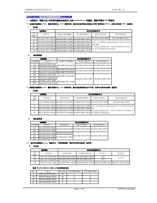
特约代理销售上海泽滔实业有限公司S120驱动器&伺服电机选型手册·2008.01 Sinamics S120系列丛书目录第一章 SINAMICS S120 DC/AC多轴驱动器概述 (3)第二章电源模块 (4)2.1基本型电源模块-BLM (Basic Line Module) (6)2.2 智能型电源模块-SLM (Smart Line Module) (10)2.3 主动型电源模块-ALM (Active Line Module) (13)第三章电机模块 (18)3.1 书本型电机模块 (Motor Module-Booksize ) (18)3.2 装机装柜型电机模块 (Motor Module-Chassis format) (21)3.3 电机模块订货的注意事项 (23)第四章控制单元及外围设备 (24)4.1 控制单元-CU320 (24)4.2 制动单元及制动电阻 (27)4.3 接口模块 (28)第五章 SINAMICS S120 AC/AC单轴驱动器的概述 (33)第六章控制单元 (35)6.1 CU310DP和CU310PN (35)6.2 CUA31 (38)第七章功率模块 (39)7.1 模块型功率模块PM340 (39)7.2 装机装柜型功率模块PM340 (41)第八章订货数据 (43)8.1 控制单元及相关的附件 (43)8.2 模块型功率模块 (43)8.3 装机装柜型功率模块 (46)8.4 编码器转换模块 (47)第九章电缆 (48)9.1 电机功率电缆 (48)9.2 电机功率电缆的详细订货数据 (49)9.3 信号电缆的订货数据 (52)第十章同步和异步伺服电机 (61)第十一章运动控制系统SIMOTION (101)11.1 系统简介 (101)11.2 订货数据 (101)S120驱动器&伺服电机选型手册·2008.01 Sinamics S120系列丛书第一部分 SINAMICS S120 DC/AC— 共直流母线的多轴驱动器控制单元 电源模块电机模块典型结构CU320ALM / SLM / BLM书本型装机装柜型书本型装机装柜型传感器模块带有标准 编码器接口的电机带有Drive-CLIQ 接口的 电机 不带编码器的电机 电抗器电源滤波器端子模块选件板+24V 电源说明:1: 主控制模块2: 电源模块3: 单轴电机模块4: 双轴电机模块 : 装有Starter(或SCOUT)和Simatic Manager 软件 的PC 机,或S7-300/400、Simotion C/D/P24 V DC特约代理销售上海泽滔实业有限公司Sinamics S120系列丛书 S120驱动器&伺服电机选型手册·2008.01 特约代理销售上海泽滔实业有限公司第一章 SINAMICS S120 DC/AC多轴驱动器概述Sinamics S120是西门子公司推出的全新的集V/F、矢量控制及伺服控制于一体的驱动控制系统,它不仅能控制普通的三相异步电动机,还能控制同步电机、扭矩电机及直线电机。

SINAMICS S120入门手册2008/10版西门子(中国)有限公司自动化与驱动集团运动控制部目 录1 SINAMICS S120概述 (1)1.1 SINAMICS S120 驱动系统的组成 (1)1.2 SINAMICS S120 的指示灯 (4)1.3 SINAMICS S120 实验设备 (8)2 SINAMICS S120项目配置 (10)2.1离线配置 (11)2.2在线配置 (21)3 基本调试 (30)3.1 控制面板(Control Panel)控制电机 (31)3.2 操作盒(Control Box)控制电机 (34)3.3 电机动态特性的调试 (37)4 基本定位 (44)4.1 激活基本定位功能 (44)4.2 点动(Jog) (47)4.3 回零(Homing) (49)4.3.1 设置参考点(Set Reference) (49)4.3.2 主动回零(Active Homing) (51)4.3.3 被动回零(Passive Homing) (53)4.4 限位(Limit) (55)4.5 程序步(Traversing Blocks) (55)4.6 手动数据输入(MDI) (57)5 通讯 (60)5.1 S120与 HMI直接通讯 (60)5.1.1 网络地址设置 (60)5.1.2 项目配置 (62)5.1.3 建立变量表 (64)5.2 通过DP总线实现S7-300与S120的通讯 (66)5.2.1 网络地址设置 (66)5.2.2 通讯报文设置 (67)5.2.3 用DP总线对电机起、停及速度控制 (68)5.2.4 驱动器参数的读取及写入 (70)1 SINAMICS S120 概述SINAMICS S120作为西门子SINAMICS驱动系列之一,可以提供高性能的单轴和双轴驱动,模块化的设计可以满足应用中日益增长的对驱动系统轴数量和性能的要求。
1.1 SINAMICS S120驱动系统的组成SINAMICS S120驱动器包括:用于单轴的AC/AC变频器和用于公共直流母线的DC/AC逆变器。

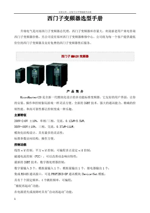
西门子变频器选型手册升瑞电气是河南西门子变频器总代理,西门子变频器库存量大,欢迎新老用户来电咨询西门子变频器价格,另公司设有郑州西门子变频器维修中心。
公司将为每一个客户提供最低价位的西门子变频器及良好免费的西门子变频器售后服务。
产品简介MicroMaster420是全新一代模块化设计的多功能标准变频器。
它友好的用户界面,让你的安装、操作和控制象玩游戏一样灵活方便。
全新的IGBT技术、强大的通讯能力、精确的控制性能、和高可靠性都让控制变成一种乐趣。
主要特征200V-240V ±10%,单相/三相,交流,0.12kW-5.5kW;380V-480V±10%,三相,交流,0.37kW-11kW;模块化结构设计,具有最多的灵活性;标准参数访问结构,操作方便。
控制功能线性v/f控制,平方v/f控制,可编程多点设定v/f控制;磁通电流控制(FCC),可以改善动态响应特性;最新的IGBT技术,数字微处理器控制;数字量输入3个,模拟量输入1个,模拟量输出1个,继电器输出1个;集成RS485通讯接口,可选PROFIBUS-DP通讯模块/Device-Net模板;具有7个固定频率,4个跳转频率,可编程;"捕捉再起动"功能;在电源消失或故障时具有"自动再起动"功能;灵活的斜坡函数发生器,带有起始段和结束段的平滑特性;快速电流限制(FCL),防止运行中不应有的跳闸;有直流制动和复合制动方式提高制动性能;采用BiCo技术,实现I/O端口自由连接。
保护功能过载能力为150%额定负载电流,持续时间60秒;过电压、欠电压保护;变频器过温保护;接地故障保护,短路保护;I2t电动机过热保护;采用PTC通过数字端接入的电机过热保护;采用PIN编号实现参数连锁;闭锁电机保护,防止失速保护。
产品简介MicroMaster430是全新一代标准变频器中的风机和泵类变转矩负载专家。
功率范围7.5kW至250kW。
高性能多机传动变频调速柜SINAMICS S120CM具有 DRIVE-CLiQ 网络技术的解决方案—高性能,全应用,多传动DRIVE-CLiQ传动网络技术的新革命高度灵活的模块化柜体设计威图柜 Rittal TS8,令人赏心悦目。
全镀镍母排,提高了连接容量,增强了抗腐蚀能力。
“功能分区”概念,提高了操作安全性。
严格的 EMC 措施,提高了系统的抗干扰能力。
• 全新通讯链接 DRIVE-CLiQDRIVE-CLiQ 构筑起传动链接,基于网络技术传动级的通讯,数据传输的电流时钟可快至 125μs 。
• 超强的控制单元 CU320一个控制单元控制多个逆变器。
• 简单并联就可实现功率扩展多个功率单元并联可组合出需要的功率。
较之上一代产品的显著特点• 逆变并联可无需平衡电抗器无环流设计省去了输出侧笨重的电抗器。
• 无需自藕变压器的整流/回馈采用可控器件整流,避免逆变颠覆的风险,同时还省去了自藕变压器,使之能更广泛应用于需高可靠性的场合。
什么是 SINAMICS S120CM集中的进线,多种整流方式,公共直流母线逆变。
符合新一代的节能环保概念。
SINAMICS S120CM 变频调速柜具备了新一代 SINAMICS 产品家族的所有特点:标准的 SIZER 工具用于工程设计 标准的 STARTER工具用于调试标准的 DRIVE-CLiQ电缆标准带 Profibus 的控制单元 CU320• 高速工业以太网 Profinet与普遍流行的工业以态网标准 TCP IP 实现无缝连接,速率更可高达全双工 100Mbps 。
• 可调的开关频率和矢量控制模式1.25K~8K 的开关频率可调,SVM 、PEM 的调制模式可选,实现传动性能和输出波形的最优化。
采用 DRIVE-CLiQ 技术,高度灵活的柜体组合,美观的柜体皆秉承了西门子一贯的精品理念。
SINAMICS S120CM 作为西门子新一代多机传动变频器,其强大的功能可使其应用于各种场合。
SINAMICS S120入门手册2008/10版西门子(中国)有限公司自动化与驱动集团运动控制部目 录1 SINAMICS S120概述 (1)1.1 SINAMICS S120 驱动系统的组成 (1)1.2 SINAMICS S120 的指示灯 (4)1.3 SINAMICS S120 实验设备 (8)2 SINAMICS S120项目配置 (10)2.1离线配置 (11)2.2在线配置 (21)3 基本调试 (30)3.1 控制面板(Control Panel)控制电机 (31)3.2 操作盒(Control Box)控制电机 (34)3.3 电机动态特性的调试 (37)4 基本定位 (44)4.1 激活基本定位功能 (44)4.2 点动(Jog) (47)4.3 回零(Homing) (49)4.3.1 设置参考点(Set Reference) (49)4.3.2 主动回零(Active Homing) (51)4.3.3 被动回零(Passive Homing) (53)4.4 限位(Limit) (55)4.5 程序步(Traversing Blocks) (55)4.6 手动数据输入(MDI) (57)5 通讯 (60)5.1 S120与 HMI直接通讯 (60)5.1.1 网络地址设置 (60)5.1.2 项目配置 (62)5.1.3 建立变量表 (64)5.2 通过DP总线实现S7-300与S120的通讯 (66)5.2.1 网络地址设置 (66)5.2.2 通讯报文设置 (67)5.2.3 用DP总线对电机起、停及速度控制 (68)5.2.4 驱动器参数的读取及写入 (70)1 SINAMICS S120 概述SINAMICS S120作为西门子SINAMICS驱动系列之一,可以提供高性能的单轴和双轴驱动,模块化的设计可以满足应用中日益增长的对驱动系统轴数量和性能的要求。
1.1 SINAMICS S120驱动系统的组成SINAMICS S120驱动器包括:用于单轴的AC/AC变频器和用于公共直流母线的DC/AC逆变器。
9/47Siemens NC 61 · 2007/20089■OverviewA wide range of single-axis and two-axis Motor Modules with graded current/power ratings can be supplied:•Single Motor Modules: Single-axis variantBooksize format with rated output currents of 3A to 200 A •Double Motor Modules: Two-axis variantBooksize format with rated output currents of 3A to 18 A In principle, all Single Motor and Double Motor Modules can be operated on Smart Line Modules or Active Line Modules for the corresponding voltage range.■DesignThe Single Motor Modules in booksize format feature the following interfaces as standard:•2 DC link connections via integrated DC link busbars •1 electronics power supply connection via integrated 24V DC busbars•3 DRIVE-CLiQ sockets•1 motor connection, plug-in (not included in scope of supply) or screw-stud depending on rated output current •1 safe standstill input (enable pulses)•1 safe motor brake control•1 temperature sensor input (KTY84-130 or PTC)•2 PE (protective earth) connectionsThe status of the Motor Modules is indicated via two multi-color LEDs.The motor cable shield is inside the connector on 50 mm (1.97 in) and 100 mm (3.94 in) width modules. A shield connection kit can be supplied for 150 mm, 200 mm and300 mm (5.91 in, 7.87 in and 11.81 in) wide modules. On these modules, the motor cable shield can be connected using a tube clip.The signal cable shield can be connected to the Motor Module by means of a shield connection terminal, e.g. Weidmüller type KLBÜ3-8SC.■Design (continued)The scope of supply of the Motor Modules includes:•DRIVE-CLiQ cable (length depends on module width) to connect Motor Module to adjacent module•Jumper for connecting the 24V DC busbar to the adjacent Motor Module •Connector X21•Connector X11 for the motor brake connection (for Motor Modules with a rated output current of 45A to 200A)•2 blanking plugs for sealing unused DRIVE-CLiQ sockets•Fan insert for the 132 A and 200 A Motor Modules (the voltage for the fan insert is supplied by the Motor Module)•1 set of warning signs in foreign languages■IntegrationSingle Motor Modules communicate with a CU320 Control Unit or SINUMERIK solution line via DRIVE-CLiQ.■Technical specifications1)Note correlation between max. output frequency, pulse frequencyand current derating; see system description on the CD-ROMsupplied with the catalog for further information.General technical specificationsSiemens NC 61 · 2007/20089■Technical specifications (continued)1)Rated DC link current for dimensioning an external DC connection. For DC link current calculation for dimensioning the Line Module,see system description "Power units/Line Modules" on the CD-ROM supplied with the catalog.2)Power loss of Motor Module at rated power without losses of 24 V DC electronics power supply.3)Not included in scope of supply, see Accessories.DC link voltage 510 ... 720 V DC Order No.•Internal air cooling 6SL3120-1TE13-0AA36SL3120-1TE15-0AA36SL3120-1TE21-0AA36SL3120-1TE21-8AA36SL3120-1TE23-0AA3•External air cooling 6SL3121-1TE13-0AA36SL3121-1TE15-0AA36SL3121-1TE21-0AA36SL3121-1TE21-8AA36SL3121-1TE23-0AA3Product name Single Motor Modules in booksize format Output current•Rated current I rated A 3591830•Base load current I H A 2.6 4.37.715.325.5•for S6 duty (40%)I S6A 3.56102440•I max , maximumA610183656Power•with 600 V DC link voltage kW (HP)1.6 (1.5) 2.7 (3) 4.8 (5)9.7 (10)16.0 (20)•based on I H kW (HP)1.4 (1) 2.3 (2.5) 4.1 (5)8.2 (10)13.7 (18)Rated pulse frequency kHz 44444DC link current I d 1)A 3.66112236Current capacity •24 V DC busbarsA2020202020If, due to a number of Line and Motor Modules being mounted side-by-side, the current carrying capacity exceeds 20 A, an additional 24V DC connection using a 24V terminal adapter is required (connection cross-section, max. 6mm 2, fuse protection, max. 20 A).•DC link busbars A 100100100100100DC link capacitance μF 110110*********Current requirement with 24 V DC, max.A0.850.850.850.850.9Power loss•Internal air cooling kW0.0350.0550.0800.1650.290•External air cooling int./ext.2)kW 0.015/0.0150.023/0.030.035/0.0450.075/0.090.08/0.210Cooling air requirement m 3/s (ft 3/s)0.008(0.283)0.008(0.283)0.008(0.283)0.008(0.283)0.016(0.565)Sound pressure level dB (A)<60<60<60<60<60Motor connection U2, V2, W2Plug-in connector (X1)3), max. 30A Shield connection Integrated in connector (X1)PE connectionOn housing with M5 screwMotor brake connection Integrated into the plug-in motor connector (X1), 24 V DC, 2 AMotor cable length, max.•Shielded m (ft)50 (164)50 (164)50 (164)70 (230)70 (230)•Unshielded m (ft)75 (246)75 (246)75 (246)100 (328)100 (328)Degree of protection IP20IP20IP20IP20IP20Dimensions •Width mm (in)50 (1.97)50 (1.97)50 (1.97)50 (1.97)100 (3.94)•Height mm (in)380 (14.98)380 (14.98)380 (14.98)380 (14.98)380 (14.98)•Depth-with internal air cooling mm (in)270 (10.63)270 (10.63)270 (10.63)270 (10.63)270 (10.63)-with external air cooling in front of/behind mounting surface mm (in)226/66.5 (8.9/2.6)226/66.5 (8.9/2.6)226/66.5 (8.9/2.6)226/66.5 (8.9/2.6)226/66.5 (8.9/2.6)Weight, approx.•with internal air cooling kg (lb) 5.0 (11) 5.0 (11) 5.0 (11) 5.0 (11) 6.9 (15)•with external air coolingkg (lb) 5.7 (13) 5.7 (13) 5.7 (13) 5.7 (13)8.5 (19)Siemens NC 61 · 2007/20089■Technical specifications (continued)1)Rated DC link current for dimensioning an external DC connection.For DC link current calculation for dimensioning the Line Module, see system description "Power units/Line Modules" on the CD-ROM supplied with the catalog.2)Power loss of Motor Module at rated power without losses of 24 V DC electronics power supply.3)The fan is supplied with the Motor Module and must be installed before the Motor Module is commissioned.DC link voltage 510 ... 720 V DC Ordering data •Internal air cooling 6SL3120-1TE24-5AA36SL3120-1TE26-0AA36SL3120-1TE28-5AA36SL3120-1TE31-3AA36SL3120-1TE32-0AA3•External air cooling 6SL3121-1TE24-5AA36SL3121-1TE26-0AA36SL3121-1TE28-5AA36SL3121-1TE31-3AA36SL3121-1TE32-0AA3Product name Single Motor Modules in booksize format Output current•Rated current I rated A 456085132200•Base load current I H A 385168105141•for S6 duty (40%)I S6A 6080110150250•I max , maximumA85113141210282Power•with 600 V DC link voltage kW (HP)24 (30)32 (40)46 (60)71 (100)107 (150)•based on I H kW (HP)21 (25)28 (40)37 (50)57 (75)76 (100)Rated pulse frequency kHz 44444DC link current I d 1)A 5472102158200Current capacity •24 V DC busbarsA2020202020If, due to a number of Line and Motor Modules being mounted side-by-side, the current carrying capacity exceeds 20 A, an additional 24V DC connection using a 24V terminal adapter is required (connection cross-section, max. 6mm 2, fuse protection, max. 20 A).•DC link busbars A 200200200200200DC link capacitance μF 11751410188028203995Current requirement with 24 V DC, max.A1.21.21.51.51.5Power loss•Internal air cooling in control cabinetkW 0.430.590.75 1.25 2.05•External air cooling int./ext.2)kW 0.011/0.320.135/0.4550.16/0.590.25/1.00.4/1.65Cooling air requirement m 3/s(ft 3/s)0.031(1.095)0.031(1.095)0.044(1.554)0.144(5.085)0.144(5.085)Sound pressure leveldB (A)<65<65<60<73<73Motor connection U2, V2, W2M6 screw studs, (X1)M6 screw studs, (X1)M8 screw studs, (X1)M8 screw studs, (X1)M8 screw studs, (X1)•Conductor cross-section mm 2 2.5...50 2.5...50 2.5...95, 2×35 2.5...120, 2×50 2.5...120, 2×50Shield connection See Accessories See Accessories See Accessories See Accessories See Accessories PE connectionOn housing with M6 screwOn housing with M6 screwOn housing with M6 screwOn housing with M8 screwOn housing with M8 screwMotor brake connection Plug-in connector (X11), 24 V DC, 2 A Plug-in connector (X11), 24 V DC, 2 A Plug-in connector (X11), 24 V DC, 2 A Plug-in connector (X11), 24 V DC, 2 A Plug-in connector (X11), 24 V DC, 2 A Motor cable length, max.•Shielded m (ft)100 (328)100 (328)100 (328)100 (328)100 (328)•Unshielded m (ft)150 (492)150 (492)150 (492)150 (492)150 (492)Degree of protection IP20IP20IP20IP20IP20Dimensions •Width mm (in)150 (5.91)150 (5.91)200 (7.87)300 (11.81)300 (11.81)•Heightmm (in)380 (14.96)380 (14.96)380 (14.96)380, (14.96)with fan 3): 629 (24.8)380, (14.96)with fan 3): 629 (24.8)•Depth-with internal air cooling mm (in)270 (10.63)270 (10.63)270 (10.63)270 (10.63)270 (10.63)-with external air cooling in front of/behind mounting surface mm (in)226/71 (8.9/2.8)226/71 (8.9/2.8)226/92 (8.9/3.6)226/82 (8.9/3.2)226/82 (8.9/3.2)Weight, approx.•with internal air cooling kg (lb)9 (20)9 (20)15 (33)21 (46)21 (46)•with external air coolingkg (lb)13.2 (29)13.4 (30)17.2 (38)27.2 (60)30 (66)9■Selection and Ordering Data■Accessories (continued)9/50Siemens NC 61 · 2007/20089/51Siemens NC 61 · 2007/20089■Characteristic curvesOverload capabilityDuty cycle with previous load Duty cycle without previous load S6 duty cycle with previous load with a duty cycle duration of 600 s S6 duty cycle with previous load with a duty cycle duration of 60 sDuty cycle with 60 s overload with a duty cycle duration of 300 sDuty cycle with 30 s overload with a duty cycle duration of 300 s9■Characteristic curves (continued)Derating characteristicsOutput current dependent on pulse frequencyOutput current dependent on ambient temperatureOutput current dependent on installation altitudeVoltage derating dependent on pulse frequency9/52Siemens NC 61 · 2007/2008。