V90选型手册
- 格式:pdf
- 大小:3.85 MB
- 文档页数:28
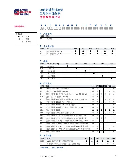
LB系列机座号(mm):80、110、130、150额定转矩(Nm):1.3~27额定功率(Kw):0.4~5.5额定转速(rpm):1500、2000、2500、3000最高转速(rpm):/转子惯量:中惯量标配反馈元件:增量式编码器(2500C/T)失电制动器:可配适配驱动器工作电压(VAC):220LBB系列机座号(mm):80、110、130、150额定转矩(Nm):1.3~19.1额定功率(Kw):0.4~3.0额定转速(rpm):1500、2000、3000最高转速(rpm):3000、5000转子惯量:中惯量标配反馈元件:总线式光电编码器失电制动器:可配适配驱动器工作电压(VAC):220HB系列机座号(mm):110、130、150额定转矩(Nm):2~27额定功率(Kw):0.6~5.5额定转速(rpm):1500、2000、2500、3000最高转速(rpm):/转子惯量:中惯量标配反馈元件:增量式编码器(2500C/T)失电制动器:可配适配驱动器工作电压(VAC):380HBB系列机座号(mm):110、130、150额定转矩(Nm):2.4~28.7额定功率(Kw):0.4~5.5额定转速(rpm):1500、2000最高转速(rpm):3000转子惯量:中惯量标配反馈元件:总线式光电编码器失电制动器:可配适配驱动器工作电压(VAC):380请您关注以下伺服电机为自冷式散热方式,安装时请选择足够大的安装板。
伺服电机长期工作,机体本身会有一定的温度,这是正常情况。
装配了失电制动器的伺服电机,其失电制动器的电源必须由驱动器控制开闭,否则会造成工作状态不佳。
伺服电机内装精密反馈元件,严禁重力敲击电机轴伸端及后部。
请注意电机轴伸端的最大径、轴向力的限值。
严禁随意更改、拆装及加工电机部件。
请您将需求告之我们,我们来为您服务。
电机电联接器转矩转速曲线示意图LB 、HB系列 LBB 、HBB 系列LB、LBB 、HB 、HBB 系列伺服电机的Mmax=3Mn ;Mmax 输出状态为短时工作。
3×44 metres of leading edgeIn our quest to boost the efficiency of the V90, wemade sweeping improvements to two aspects ofour turbine blades: their material composition andtheir structureWe at Vestas have long enjoyed a reputation formaking some of the lightest blades on the market,and with the V90 we have once again raised the bar.We began by introducing several new lightweightmaterials, most notably carbon fibre for the load-bearing spars. Not only is carbon fibre intrinsicallylighter than the fibreglass it replaces, but itsstrength and rigidity also reduce the quantity ofmaterial needed – thus cutting overall weight evenfurther. So that even though the V90 has a sweptarea that is 27 per cent more than the V80, the newblades actually weigh about the same.The new profile of the V90 blades also represents asig-nificant aerodynamic advance. In collaborationwith Risø National Laboratory in Denmark, Vestasengineers worked on optimising the relationshipbetween the overall load impact on the turbine andthe volume of energy generated annually. Their finalblade design features an entirely new plane shapeand a curved back edge.The resulting airfoil improves energy production,while making the blade profile less sensitive to dirton the leading edge and maintaining a favourablegeometrical relationship between successive airfoilthicknesses. This translates into an increase inoutput combined with a decrease in load transfers– as well as improvements on the bottom line.Reduced need for service and maintenanceA series of improvements to the V90 have madeservice and maintenance calls less demanding– and less frequent. Turbine access has beensimplified and working areas expanded, while thearrangement of tower and nacelle components hasbeen optimised to facilitate service proce-dures. Moreover, a variety of new features, ranging from automatic blade-bearing lubrication to an oil-lubricated yaw system, have made it possible to reduce the number of preventive maintenance visits to one a year. This means considerable savings in turbine downtime and personnel costs, and is a particularly welcome development in the context of hard-to-reach offshore installations. Proven Performance Wind power plants require substantial investments, and the process can be very complex. To assist in the evaluation and purchasing process, Vestas has identified three factors that are critical to wind turbine quality: energy production, power quality and sound level.We spend months testing and documenting these performance areas for all Vestas turbines. When we are finally satisfied, we ask an independent testing organisation to verify the results – a practice we call Proven Performance. At Vestas we do not just talk about quality. We prove it.Innovations in blade technologyg h b d e c f 6789a 132453,5003,2503,0002,7502,5002,2502,0001,7501,5001,2501,000750500250051015202512345 6789a b c d e f g hOil coolerWater cooler for generatorHigh voltage transformerUltrasonic wind sensors VMP-Top controller with converter Service crane OptiSpeed® generator Composite disc coupling Yaw gears Gearbox Mechanical disc brake Machine foundation Blade bearing Blade hub Blade Pitch cylinder Hub controllerTechnical specificationsPower curve V90-3.0 MWWind speed (m/s)P o w e r (k W )30252015103025201510501,9001,7001,5001,3001,1009003,5003,0002,5002,0001,5001,000OptiSpeed ® allows the rotor speed to vary within a range of approximately 60 percent in relation to nominal rpm. Thus with OptiSpeed ®, the rotor speed can varyby as much as 30 per cent above and below synchronous speed. This minimises bothunwanted fluctuations in the output to the grid supply and the loads on the vitalparts of the construction.*Vestas OptiSpeed ® is not available in the USA and Canada.WindS peed (m /s)TimePitchA ng le(de g ree s)TimeGeneratorS peed(rpm )TimeOutputP o w e r(k W )TimeWhen Vestas set out to establish a new benchmark for efficiency with its development of the V90-3.0 MW turbine, high priority was given to keeping weight down. That is because wind turbines are heavy, and the heavier the turbine, the greater the costs – for production, material, transport and installation.Our engineers therefore rethought every aspect of turbine design – from foundations to blade tip – seeking ways to minimise the cost per kWh over the design lifetime of the V90. The result is a showcase of innovative engineering – particularly as regards weight saved. In fact, despite a larger rotor and generator, the new V90 actually weighs less than the V80-2.0 MW.The biggest reduction has come from strengthening the tower. To increase fatigue strength, we have pioneered the use of magnets to fasten internal components to the tower walls. In addition, using a stronger steel means less is needed. The decreased weight lets us construct the new towers in fewer sections, with significant savings in material, transport, and installation costs.The most radical redesign centred on the new nacelle. Even though the 3 MW generator is 50 per cent larger than the corresponding generator in the 2 MW wind turbine, we kept overall nacelle weight almost the same. We did this by integrating the hub bedplate directly into the gearbox, eliminating the main shaft and thus shortening nacelle length. The result is a nacelle that can generate much more power without any appreciable increase in size, w eight or tower load.Together with new low-weight blades, these breakthroughs have made the V90 remarkably light for a turbine of its size – and remarkably efficient for a turbine of any dimension.An efficient way to more power09/07 U K。
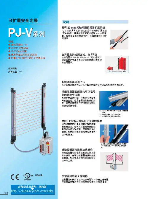
204OSHA详细信息及资料,请浏览/askg特性●操作范围达 7 m ●20 mm 光轴间距●IP-65 防水外壳●高度节省成本的扩充系统●内置 LED 指示灯简化了校准工作检测距离所有机型 - 7 m可扩展安全光栅长检测距离可达 7 m充分的检测距离保证了从小型到大型的各种设备或机器的可靠防护。
纤细而坚固的感测头可以在苛刻的环境中应用虽然外壳非常纤细,但感测头具备很高的坚固性。
使用金属材料制作的外壳、内壳及固定配件使得感测头可以耐振动或抗冲击。
柱状 LED 指示灯简化了光轴的校准指示灯亮起的数目会随着光轴的校准数目而改变。
任何人不需协助就能独自轻松执行光轴校准。
而且在发生故障时,指示灯可立即通知操作员有关故障的情况。
辅助控制器可进行双头操作辅助控制器可以使用双感测头而不需另外接线。
当辅助控制器连接到主控制器时,那么相互干扰抑制功能会自动开始工作。
节省空间的安全控制器控制器特别安装了故障检测电路和 3 个安全继电器。
控制器非常精巧可以很容易地安装到 DIN 轨道上。
* 1. 1.6 mm 厚的铝质外壳不仅坚固,而且重量很轻。
* 2.特制的内壳可以防止外物的侵入。
* 3.立体模制的坚固钢制结构构件。
*当所有光轴都很稳定而且清晰时,所有的LED 都会亮起,LED 颜色自红色转为绿色。
*1*3辅助控制器扩充单元扩充单元扩充单元205206控制器连接缆线207指示灯状态亮起个安全继电器以确保安全。
一个“常开”接点及一个“常闭”接点被连接在一起共同运作。
当一个继电器被一个焊合接点阻止运作时,可根据其它继电器的接点间隙而将此焊合接点检测出来,从而确保安全。
故障保险一旦系统中发生故障时,故障保险系统会立即工作以确保安全。
例如,当接收到环境光线或输出线路损坏,此时如果有人接近机器上的危险区域,普通的光电传感器无法将机器停止。
因此这样的传感器不能用来进行系统故障保险。
PJ-V 系列能使用两组独立电路执行自我检查以检测线路中的故障,环境光线的侵入或一个继电器接点被焊合。
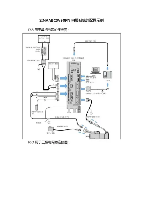
SINAMICSV90PN伺服系统的配置示例FSB 用于单相电网的连接图:
FSD 用于三相电网的连接图:
⚠警告接线错误导致人身伤害和设备损坏
错误的接线会导致较高的电击和短路风险,从而会对人员安全和设备造成危害。
· 驱动与电机必须直接连接。
在它们之间不可连接电容器、感应器或者滤波器。
· 主电源电压必须处在允许的电压范围(参见驱动铭牌)之内。
切忌将电源电缆与电机端子U、V、W 连接,切忌将电机动力电缆与电源输入端子 L1、L2、L3 连接。
· 切忌不按U、V、W 相位顺序进行接线。
· 在某些情况下,如果必须在电缆上加示 CE 标记,则电机动力电缆、电源电缆和抱闸电缆都必须使用屏蔽电缆。
· 在进行端子连接时,须确保非绝缘带电部件之间的间距至少为5.5 mm。
· 信号电缆和动力电缆需分开敷设在不同的电缆槽中。
信号电缆必须与动力电缆保持 10 cm 以上的距离。
· 已连接的电缆不可与旋转的机械部件接触。
重要接线提示
为满足 EMC 要求,所有电缆都应屏蔽。
屏蔽双绞线的屏蔽层应连接至伺服驱动的屏蔽板或电缆夹。
屏蔽线与PROFINET I/O 连接器上未使用的针脚短接造成驱动损坏可能不小心将屏蔽线与要装配的 PROFINET I/O 连接器上未使用的针脚短接。
此操作会造成驱动损坏。
请在连接屏蔽电缆与PROFINET I/O 连接器时谨慎操作。
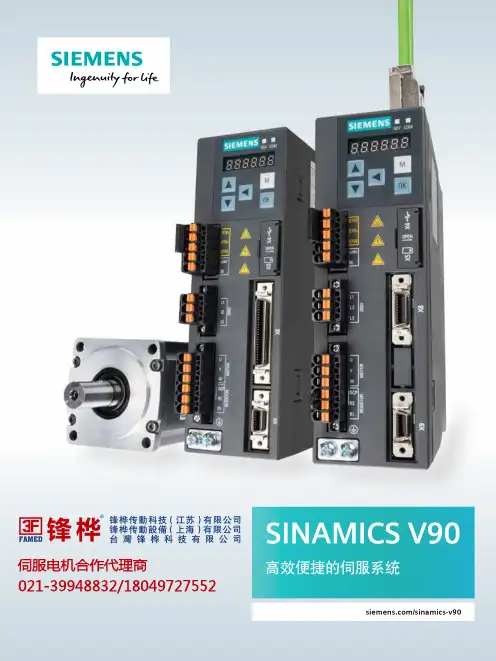
伺服电机合作代理商021-********/180********2目录伺服驱动系统SINAMICS V90 伺服驱动和 SIMOTICS S-1FL6 伺服电机组成了性能优化,易于使用的伺服驱动系统,八种驱动类型,七种不同的电机轴高规格,功率范围从0.05kW 到7.0kW 以及单相和三相的供电系统使其可以广泛用于各行各业,如:定位,传送,收卷等设备中,同时该伺服系统可以与S7-1500T/S7-1500/S7-1200 进行完美配合实现丰富的运动控制功能。
伺服驱动系统概述 ..................................................03伺服驱动系统优点 ..................................................05SINAMICS V90 伺服驱动系统 的自动化环境 ......................................................... 10SINAMICS V-ASSISTANT 调试工具 ..........................10SINAMICS V90 技术数据与控制特征 .......................12系统一览及接线图 ..................................................15SIMOTICS S-1FL6 技术数据 及扭矩/速度曲线 .................................................... 18SINAMICS V90 和 SIMOTICS S-1FL6 安装尺寸及安装间距 ............................................... 22选型步骤 ...............................................................26SINAMICS V90 和 SIMOTICS S-1FL6 订货数据 (27)3脉冲序列版本 (PTI)PROFINET 版本 (PN)SINAMICS V90 伺服驱动SINAMICS V90 根据不同的应用分为两个版本:1. 脉冲序列版本(集成了脉冲,模拟量,USS/MODBUS )2. PROFINET 通讯版本SINAMICS V90 脉冲版本可以实现内部定位块功能,同时具有脉冲位置控制,速度控制,力矩控制模式。
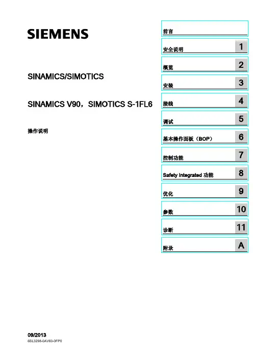
SINAMICS/SIMOTICS SINAMICS V90,SIMOTICS S-1FL6 操作说明Siemens AG Industry Sector Postfach 48 48 90026 NÜRNBERG 文件订购号: 6SL3298-0AV60-0FP0Ⓟ 09/2013 本公司保留技术更改的权利Copyright © Siemens AG 2013.保留所有权利法律资讯警告提示系统为了您的人身安全以及避免财产损失,必须注意本手册中的提示。
人身安全的提示用一个警告三角表示,仅与财产损失有关的提示不带警告三角。
警告提示根据危险等级由高到低如下表示。
危险表示如果不采取相应的小心措施,将会导致死亡或者严重的人身伤害。
警告表示如果不采取相应的小心措施,可能导致死亡或者严重的人身伤害。
小心表示如果不采取相应的小心措施,可能导致轻微的人身伤害。
注意表示如果不采取相应的小心措施,可能导致财产损失。
当出现多个危险等级的情况下,每次总是使用最高等级的警告提示。
如果在某个警告提示中带有警告可能导致人身伤害的警告三角,则可能在该警告提示中另外还附带有可能导致财产损失的警告。
合格的专业人员本文件所属的产品/系统只允许由符合各项工作要求的合格人员进行操作。
其操作必须遵照各自附带的文件说明,特别是其中的安全及警告提示。
由于具备相关培训及经验,合格人员可以察觉本产品/系统的风险,并避免可能的危险。
按规定使用Siemens 产品请注意下列说明:警告Siemens 产品只允许用于目录和相关技术文件中规定的使用情况。
如果要使用其他公司的产品和组件,必须得到Siemens 推荐和允许。
正确的运输、储存、组装、装配、安装、调试、操作和维护是产品安全、正常运行的前提。
必须保证允许的环境条件。
必须注意相关文件中的提示。
商标所有带有标记符号 ® 的都是西门子股份有限公司的注册商标。
本印刷品中的其他符号可能是一些其他商标。
运动控制解决方案西门子制造自动化和驱动技术集团的运动控制系统部门已推出了一套完整的自动化解决方案,可以满足未来对机床和生产机械的需求。
凭借其强大的创新能力,行业知识以及这些解决方案的巨大优势,西门子已成为全球领先的运动控制系统提供商之一。
因此,我们可以在不同领域提供成功的案例供您参考。
面向各个行业的创新产品,系统,解决方案和服务西门子运动控制系统可以满足很高的要求:所有产品均采用最新技术,具有强大的功能和高质量。
此外,系统和产品以最佳方式组合在一起,因此它们始终可以轻松组合到经济的机器解决方案中。
相似和运动控制系统如下所述。
这些产品构成了创新的系统平台,可用于优化控制系统以满足机床的要求。
因此,对于包装,塑料和玻璃,木材和金属,纺织和印刷等众多行业,可以找到最好的经济型运动控制解决方案来满足未来的需求。
这些解决方案可以根据新出现的新要求轻松扩展,并且可以与我们的高性能伺服电机,线性电机,转矩电机和标准准电机结合使用。
此外,西门子在机器的整个生命周期内为客户提供支持,例如在130个国家/地区的295个服务点提供售前和售后服务,或在运动控制解决方案的应用咨询和机电支持等特殊服务方面提供支持。
应用程序支持:寻求最佳解决方案的安全途径:中国,法国,德国,意大利,土耳其和美国的多个应用程序中心提供现场专家和应用程序顾问,他们将从规划到启动的整个过程中为客户的项目提供指导-从最初的构想到机器的实际运行。
应用咨询包括:6.1规划和实施项目6.1通过测试配置和仿真进行技术验证6.1开发要求和功能规范6.1应用研讨会和特定于客户的培训课程双赢的合作伙伴关系不仅为客户提供支持,而且作为技术合作伙伴系统和组件开发过程,最终获得可以满足未来需求的实用自动化解决方案。
西门子以此方式帮助客户提高生产率,竞争力和长期盈利能力。
?0.8 Siemens AG 2013系统概述通过有针对性的能源管理提高能源效率1/3 Siemens PM 21·20131在能源效率和能源管理方面,西门子树立了工业应用领域的行业标杆,能源效率对电力行业产生了重大影响驱动系统,因为该系统的能耗占工业能耗的70%以上(数据来源:ZVEI)EU-15 / 2002)西门子SIMOTION运动控制系统与SINAMICS S120驱动系统和simotics电机相结合可实现高效的解决方案,不仅效率高,而且大大降低了能耗。
1 内容与缩写内容1.内容与缩写2.前言3.贴花6.安全9.概览11.安装/调试20. 操作指令37.维护42.故障排除缩写与符号#### 同上海英格索兰压缩机有限公司联系索取序号—>#### 直到序号####—> 从序号起* 没有图示+ 选项NR 不要求AR 根据要求SM 总图HA 高环境温度选项WC 水冷却机组AC 风冷却机组ERS 能量恢复系统T.E.F.C. 闭式电机O.D.P. 开式电机2 前言该手册包含的内容应该视为上海英格索兰压缩机有限公司的财产,属于上海英格索兰压缩机有限公司的机密。
未征得上海英格索兰压缩机有限公司的事先书面许可,不得复制。
本文件中的任何内容均无意扩大文件中直接说明或间接隐含的关于上海英格索兰产品的讲话、保证和说明。
任何此类保单或产品销售的条款及条件,将遵守此类产品销售的标准条款和条件。
如有需要,可来信索取。
本指南包含指令和技术数据,以及操作和维修人员进行例行操作和定期维修所需执行的任务。
大型检修不在本指南包括范围之内,应由指定的上海英格索兰压缩机有限公司维修部门承担。
附加在压缩空气系统上的所有备件、附件、管子和连接器都必须:l有良好的质量,从知名厂家获得。
而且,如有可能,属于上海英格索兰压缩机有限公司认可的类型。
l能承受的压力至少相等于机器最大允许的工作压力。
l与空压机的润滑剂/冷却剂相容。
l伴有安全安装、操作和维修的指令。
任何设备的细节可从上海英格索兰维修部门获取。
如使用仿造备件,即不包括在上海英格索兰压缩机有限公司认可部件清单中的维修备件,可能会造成上海英格索兰压缩机有限公司无法控制的危险条件。
因此,上海英格索兰压缩机有限公司对因安装非标准维修部件所造成的损失概不承担任何责任。
标准的保质条件也会受到影响。
上海英格索兰压缩机有限公司有权不加通告便改变及改良产品,没有义务对已销产品补加改良措施。
版权2011年上海英格索兰压缩机有限公司ISO符号图形及国际标准符号的意义V SERIES 90-160 机组贴花序号 零件号 数量 名称序号 零件号 数量 名称1 99289944 1 电压380/3/50 12 19000256 1 QS 标志2 92867407 1 不准吸入符号 13 46844866 1 现场施工注意 92867498 1 排气口46846507 1 额定工况运行3 92867530 2 热表面符号 23805591 1 贴花 机组维护指南4 92930585 1 压力容器符号 14 42873139 1 铭牌5 92930593 3 电击警告符号 15 46872941 1 标签 运输支架6 92930668 1 维护 16 18990838 1 贴花 警告 19051549 1 三滤注意17 23175243 1 贴花 加油 19019348 1 贴花 开机调试 18 22141311 1 胶带 直径3’’ 23761836 1 贴花 电气原理图 19 46857777 1 Logo SIRC 7 93165959 2 转动时使用防护罩 23834203 1 贴花 前面板90-160kW 8 93165983 2 转向20 99266199 1 安装贴花 9 93166460 1 冷却剂排放符号 99266199 1 安装贴花 10 93166502 1 油滤芯更换符号 11 93171262 4 起吊前视图左视图概览操作人员在维修或操作之前须阅读并理解《贴花》,并参阅《手册》。
分度盘机构选型计算参数输入:机械系统参数分度盘质量M1=2kg分度盘直径D1= 3.7m工作物质量M2=10000kg由分度盘中心至工作物d= 1.85m中心的距离减速机减速比i =86动作模式参数定位角度θ=360。
分度盘转速N L= 1.5r/min定位时间t= 1.2s选型计算:1、折算到电机端转速电机端转速N m=N L* i=129r/min2、折算到电机端负载惯量的计算工作台的惯量J A=M1*D12/8= 3.4225kgm2工作物的惯量J B=M2*d2=34225kgm2减速机轴端负载惯量J L=J A+J B=34228.42kgm2折算到电机轴端负载惯量J=J L/i2= 4.627964kgm23、折算到电机端的负载转矩的计算由于摩擦负载极小,T L=0 Nm故可以忽略。
4、初步选定电机选定电机的额定转速大于电机端转速N m的电机n m〉129r/min选定电机的转子惯量大于1/5倍负载惯量的J L电机J m〉6845.685kgm2选定电机的额定转矩大于负载转矩T L的电机T m〉0Nm5、加减速转矩的计算加速/减速时间t a=t-θ/(6*N L)=-38.8s加减速转矩T a=2*pi*Nm*(J+J m)/(60*t a)=-1.61048Nm6、最大转矩/有效转矩的计算瞬时最大转矩T1=T a+T L=-1.61048Nm确定所选电机的最大转矩是否大于瞬时最大转矩T1?T2=T L=0NmT3=T L-T a= 1.610484Nm有效转矩==#NUM!Nm确定所选电机的额定转矩是否大于有效转矩Trms?构选型计算n m =r/min J m =kgm2 T m =NmT max =Nm T m =0Nm。
204OSHA详细信息及资料,请浏览/askg特性●操作范围达 7 m ●20 mm 光轴间距●IP-65 防水外壳●高度节省成本的扩充系统●内置 LED 指示灯简化了校准工作检测距离所有机型 - 7 m可扩展安全光栅长检测距离可达 7 m充分的检测距离保证了从小型到大型的各种设备或机器的可靠防护。
纤细而坚固的感测头可以在苛刻的环境中应用虽然外壳非常纤细,但感测头具备很高的坚固性。
使用金属材料制作的外壳、内壳及固定配件使得感测头可以耐振动或抗冲击。
柱状 LED 指示灯简化了光轴的校准指示灯亮起的数目会随着光轴的校准数目而改变。
任何人不需协助就能独自轻松执行光轴校准。
而且在发生故障时,指示灯可立即通知操作员有关故障的情况。
辅助控制器可进行双头操作辅助控制器可以使用双感测头而不需另外接线。
当辅助控制器连接到主控制器时,那么相互干扰抑制功能会自动开始工作。
节省空间的安全控制器控制器特别安装了故障检测电路和 3 个安全继电器。
控制器非常精巧可以很容易地安装到 DIN 轨道上。
* 1. 1.6 mm 厚的铝质外壳不仅坚固,而且重量很轻。
* 2.特制的内壳可以防止外物的侵入。
* 3.立体模制的坚固钢制结构构件。
*当所有光轴都很稳定而且清晰时,所有的LED 都会亮起,LED 颜色自红色转为绿色。
*1*3辅助控制器扩充单元扩充单元扩充单元205206控制器连接缆线207指示灯状态亮起个安全继电器以确保安全。
一个“常开”接点及一个“常闭”接点被连接在一起共同运作。
当一个继电器被一个焊合接点阻止运作时,可根据其它继电器的接点间隙而将此焊合接点检测出来,从而确保安全。
故障保险一旦系统中发生故障时,故障保险系统会立即工作以确保安全。
例如,当接收到环境光线或输出线路损坏,此时如果有人接近机器上的危险区域,普通的光电传感器无法将机器停止。
因此这样的传感器不能用来进行系统故障保险。
PJ-V 系列能使用两组独立电路执行自我检查以检测线路中的故障,环境光线的侵入或一个继电器接点被焊合。