【VIP专享】N-1-2 哈斯数控机床专卖店(HFO)模式及理念(HFO Model)
- 格式:pdf
- 大小:914.43 KB
- 文档页数:24


立式加工中心培训资料2007 年5 月内容目录安全 (1)操作⋯⋯⋯ (4)基本介绍⋯⋯⋯⋯⋯⋯⋯ (4)坐标体系⋯ (4)绝对定位法和增量定位 (5)用代码编程 (5)机床缺省值 (5)程序格式 (6)固定循环 (7)刀具交换装置安装步骤..................................... . (8)操作员控制面板 (9)实时计时器 (12)键盘 (12)通电/断电⋯⋯⋯ (20)手动操作⋯⋯ (20)自动操作⋯⋯⋯ (21)创建、编辑和保存程序 (23)程序输入/输出⋯ (26)试运行操作 (30)显示 (30)行程限制⋯⋯⋯⋯⋯⋯ (44)运行-停止-轻推-继续 (45)编程⋯⋯ (46)工作坐标系统 (46)编程结构 (46)字母地址代码 (48)技巧与窍门 (51)高速机械加工(可选) (61)第4轴编程 (62)子程序 (65)刀具功能(Tnn) (73)侧挂式刀具交换装置 (74)用VF系统计算机数控铣床攻丝............................ . (83)铣刀补偿 (86)高级编辑 (98)G代码(预备功能) (105)M代码(各种功能) (151)设置 (160)在工作中不要发生这种情况所有的铣削设备如旋转件、皮带、滑轮、高压电、噪音、压缩空气等均有危险存在,所以在使用CNC备及其组件时,为避免人身伤害及机械损坏,必严格遵守相应的安全守则。
操作安全必读‹ 只有经过授权的人员方可使用本机,未经培训人员在使用机床时可能对人身及机床造成伤害以及由于不正确的操作造成的问题不属保修范围内。
‹ 操作前请认真检查零配件及刀具,所有损坏的配件和刀具应当由专业人员修理或替换。
一旦有部件显示异常,不要操作,应及时联系您的车间质检人员。
‹ 操作机床时使用合适的眼、耳保护装置。
推荐使用ANSI认证的护目镜和OSHA认证的耳罩。
‹ 操作机床时一定确保其门关闭,门已正确互锁,旋转的刀具可能造成严重的人身伤害,当程序在运行中时,机床平台及主轴头能够在任一时间向任一方向做非常快的移动。
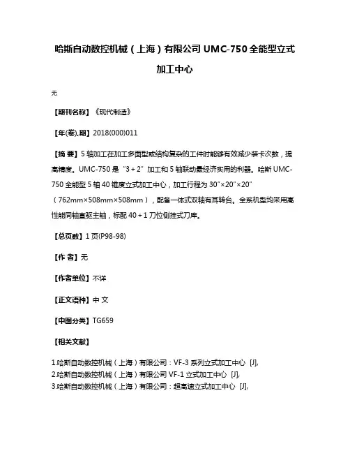
哈斯自动数控机械(上海)有限公司 UMC-750全能型立式
加工中心
无
【期刊名称】《现代制造》
【年(卷),期】2018(000)011
【摘要】5轴加工在加工多面型或结构复杂的工件时能够有效减少装卡次数,提高精度。
UMC-750是“3+2”加工和5轴联动最经济实用的利器。
哈斯UMC-750全能型5轴40锥度立式加工中心,加工行程为30″×20″×20″
(762mm×508mm×508mm),配备一体式双轴有耳转台。
全系机型均采用高性能同轴直驱主轴,标配40+1刀位侧挂式刀库。
【总页数】1页(P98-98)
【作者】无
【作者单位】不详
【正文语种】中文
【中图分类】TG659
【相关文献】
1.哈斯自动数控机械(上海)有限公司:VF-3系列立式加工中心 [J],
2.哈斯自动数控机械(上海)有限公司 VF-1立式加工中心 [J],
3.哈斯自动数控机械(上海)有限公司:超高速立式加工中心 [J],
4.哈斯自动数控机械(上海)有限公司VM-2高速立式模具加工中心 [J], 无
5.哈斯自动数控机械(上海)有限公司UMC-750全能型5轴立式加工中心 [J],因版权原因,仅展示原文概要,查看原文内容请购买。
Enterprise Development专业品质权威Analysis Report企业发展分析报告哈斯自动数控机械(上海)有限公司安徽分公司免责声明:本报告通过对该企业公开数据进行分析生成,并不完全代表我方对该企业的意见,如有错误请及时联系;本报告出于对企业发展研究目的产生,仅供参考,在任何情况下,使用本报告所引起的一切后果,我方不承担任何责任:本报告不得用于一切商业用途,如需引用或合作,请与我方联系:哈斯自动数控机械(上海)有限公司安徽分公司1企业发展分析结果1.1 企业发展指数得分企业发展指数得分哈斯自动数控机械(上海)有限公司安徽分公司综合得分说明:企业发展指数根据企业规模、企业创新、企业风险、企业活力四个维度对企业发展情况进行评价。
该企业的综合评价得分需要您得到该公司授权后,我们将协助您分析给出。
1.2 企业画像类别内容行业仓储业-装卸搬运资质一般纳税人产品服务空1.3 发展历程2工商2.1工商信息2.2工商变更2.3股东结构2.4主要人员2.5分支机构2.6对外投资2.7企业年报2.8股权出质2.9动产抵押2.10司法协助2.11清算2.12注销3投融资3.1融资历史3.2投资事件3.3核心团队3.4企业业务4企业信用4.1企业信用4.2行政许可-工商局4.3行政处罚-信用中国4.4行政处罚-工商局4.5税务评级4.6税务处罚4.7经营异常4.8经营异常-工商局4.9采购不良行为4.10产品抽查4.11产品抽查-工商局4.12欠税公告4.13环保处罚4.14被执行人5司法文书5.1法律诉讼(当事人)5.2法律诉讼(相关人)5.3开庭公告5.4被执行人5.5法院公告5.6破产暂无破产数据6企业资质6.1资质许可6.2人员资质6.3产品许可6.4特殊许可7知识产权7.1商标7.2专利7.3软件著作权7.4作品著作权7.5网站备案7.6应用APP7.7微信公众号8招标中标8.1政府招标8.2政府中标8.3央企招标8.4央企中标9标准9.1国家标准9.2行业标准9.3团体标准9.4地方标准10成果奖励10.1国家奖励10.2省部奖励10.3社会奖励10.4科技成果11土地11.1大块土地出让11.2出让公告11.3土地抵押11.4地块公示11.5大企业购地11.6土地出租11.7土地结果11.8土地转让12基金12.1国家自然基金12.2国家自然基金成果12.3国家社科基金13招聘13.1招聘信息感谢阅读:感谢您耐心地阅读这份企业调查分析报告。
Welcome to Trident Machine ToolsLive Tool Lathe TrainingHaas live tool lathetraining•This ½ day course is designed to familiarizethe user with the theory, set-up and basicprogramming of live tooling on a Haas CNClathe.Schedule•Introductions•Live tooling types•Turret configuration•Live tooling offsets•Break•Live tooling specific G and M codes•Radial live tooling canned cycles•Axial live tooling canned cyclesCNC Slant BedLathes•Most CNC slant bed lathes consistof two axis.•X –controls diameter •Z –controls depth •These machines can perform simple turning, drilling, threading, boring, etc.•All work must be done on the centerline of the spindle.4CNC Lathes with Live Tooling•Live tooling is the ability toadd milling operations to alathe.•Done by adding driven toolsthat can be bolted on theturret of the CNC lathe.•Tools will not be as powerful asa CNC mill, but reduce thenumber of set-ups needed tocomplete a part.•Tools will enable turning andmilling in one set-up.5Types of Live Tooling•Radial tools•Hold the cutting tool parallel to the face ofthe turret.•Designed to work on the diameter of thepart performing operations:•Milling•Drilling•Tapping6Types of Live Tooling•Axial tools•Hold the cutting toolperpendicular to the face ofthe turret•Designed to work on theface of the part performingoperations•Milling•Drilling•Tapping7Base Mount Turret (BMT)•The base mount turret provides extra-rigidmounting for turning and boring tools toimprove cutting performance, and offersadditional tool clearance when working with atailstock.•All tools (static or driven) need a holderinstalled to be attached to the turret.•When loading live tooling, the tools should beinstalled in the active tool position.Types of Live Tooling•Options:•Typical live tooling holdershave a 1:1 gear ratio.•The following holders can bepurchased:•High Torque-1.5: 1 ratio•Reduced RPM, increasedtorque•High Speed -1:3 ratio•Increased RPM, DecreasedTorque•Compact Size•Adjustable Angle9C Axis•The lathe spindle becomes a rotaryto be utilized by the live tooling.•This is a true rotary which canperform simultaneous cutting.• C axis enables positioning for livetooling .10Y axis•With live tooling and a C axis rotation, machinists can makecuts on the centerline of the part.•What if we want to make cuts off the centerline of the part?•The Y axis can be added to the lathe to move the turretperpendicular to the x axis.•The Haas lathes have the ability to travel +/-2.000” from spindlecenterline.•This allows features like the following to be machined:•Flats•Bolt circles on the diameter•Holes of centerline11Haas Automation Inc. “Y axis Motion." Lathe Operator's Manual.N.p.: Haas Automation Inc., 2014. 255. Print.Axial Tools•The driven tools on the Haas lathes are mounted in the VDI tool holders1212Photo Source: Exsys Tool. N.d.Web. 29 January2015.</images/catalog/archive/haas-tooling-catalog.pdf>Axial Tool Offsets •Axial tools are offset similar to turning tools:•The Z offset can be set by touching off the face of the part.•The X offset can be set by touching the tool off on the outside of the part, then adding the diameter of thetool and part to the offset.113Radial Tools•Like axial tools, radial tools are set-up in theturret.•These live tooling holders have many types ofholders that can be used:•ER collets•Endmill holders•Shellmill holders•Tap holders14Photo Source: Exsys Tool. N.d.Web. 29 January2015.</images/catalog/archive/haas-tooling-catalog.pdf>Radial Tools•Radial tools are offset opposite theaxial tools:•To set Z offset : touch the diameterof the cutting tool off the face ofthe part.•To set X offset : set end of theendmill off the outer diameter of the part, then subtract the diameter from the offset.•The coolant line of the tool shouldalso be set while doing the tool offsets.15Coolant should be adjusted herewhen setting the tool up.Photo Source: Exsys Tool. N.d.Web. 29 January2015.</images/catalog/archive/haas-tooling-catalog.pdf>Live Tooling Geometry Offsets•Both radial and axial live geometry offsets can be set with thetool setter.•Like regular turning tools, VPS can be used to set the tooloffsets.Live Tooling Geometry Offsets•After selecting VPS, enter the live tools option,then enter manual.•Manual tool setting is the only option forsetting live tool offsets.Live Tooling Geometry Offsets •After entering the manual offset page, theorientation of the tool needs to be established.•A-axial tool offset•R-radial tool offsetLive Tooling Geometry Offsets•In this case, radial has been chosen. Thisbrings up the prompt fields specific to theradial tool.•The tools diameter and tip informationwill need to be entered.•If these are improperly entered, thetools offsets could be set wrong.Live Tooling Geometry Offsets•F2 can be used to lower the tool probe.•Selecting an axis and then pressing hand jog allows the user tohand wheel the tool to the probe without leaving the screen.•After the tool is in place, F4 can be used to output the code. Inthis case, it is output to MDI.Live Tooling Geometry Offsets•With the program in MDI, the probe down, and the tool inposition, the program is ready to run.•It is important that the live tool is spinning the opposite of thetools cutting direction.•If not, the tool could grab the tool probe with contact is made.Live Tooling Geometry Offsets•The geometry offsets for the live tools are entered into theoffset page automatically.Starting the LiveTooling•M133 –Live Tool Forward•P sets the speed•M133 P3000 –would turnthe tool on at 3000 RPM•M134–Live Tool Reverse•M135–Live Tool Stop23C Axis Engagement •New Codes:•M154 –C axis engage•The C axis must be engaged tolocate and position thespindle.•M155 –C axis disengage•The C axis must be disengagedbefore using the spindle athigh RPM.24Plane Selection•Different planes can be used tomake different canned cycles andmilling tool paths work correctlyon a live tooling lathe.•Drill or Mill–refers to face work oraxial work on a live tooling lathe.•Cross Mill or Cross Drill–refers towork on the OD or radial work on alive tooling lathe.25Plane Selection •G17, G18, G19•What are these codes?•G17 –XY plane•G18 –XZ plane•G19 –YZ plane31Plane Selection•What do these planes mean?•Plane selection (G17, G18, G19) determines the main plane of work.•Think of these planes as axis selection:•G17-the Z axis positions and the main cutting axis would be X and Y .•G18-the Y axis positions and the main cutting axis would be X and Z.•G19 -the X axis positions and the main cutting axis’ would be Yand Z.32Productivity Inc., 2012. 10. Print.G17 –Axial Milling•G17is used when XY milling is takenplace.•G17is also used with G112•G112can convert XY moves toXC moves .•This means a milling toolpathcould be converted to XC moves.•G112 is used when a live toolpath needs to go beyond the Xaxis centerline but will not reach.28G18 -The Default•The turning, drilling and boring for the part would all happen with the G18 plane.•G18could also be used for the XC milling for the slot on the front face.•G18is the default for slant bedlathes.•All of the typical OD and IDturning will happen in the XZplane.•These are the main axes ofthe machine.•XC milling also happens withG18active.29G19 –Radial and Cross Drilling •G19would be used for millingthe flat on the OD of the part.•G19would also be used when drilling the four holes on the flat of the part.•G19is used with all radial andcross drilling toolpaths.•G19would also be used withany facing or millinghappening on the OD the ofpart.30G17 Plane Selection GuideCycle Description FeedrateXY AXIS MILLING MANUAL FACE PROGARMMING G98G112CARTIESAN TO POLAR G9831G18 Plane Selection GuideCycle Description FeedrateG81SIMPLE DRILLING G98G82SIMPLE DRILL W/ DWELL G98G83DRILL W/ PECK G98G95RIGID TAP G99G186RIGID TAP LEFT HAND G99X-C MILLING FACE MILLING G9832G19 Plane Selection GuideCycle Description FeedrateG241CROSS DRILL G98G242CROSS DRILL W/ DWELL G98G243CROSS DRILL W/ PECK G98G195RIGID TAP G99G196RIGID TAP LEFT HAND G9933Face and Axial Drilling•Drilling the three holes on the face of thepart can be done with the regular G80series drilling canned cycles.•The part will be programmed without apeck because of the depth.34Face and Axial Drilling•G81is programmed the same way it wouldbe on a mill or a lathe.•Note: A “C”value can be used as a positionmove during a canned cycle.•The depth is controlled by Z.•The plain needs to be set with G18.35Face and Axial Drilling•If G82is used, a P value needs to beentered for a dwell after the depth isreached.•If G83is used, a Q value needs to beentered to specify the peck amount.36G95 Live tooling rigid tap (face)•G95Live Tooling Rigid Tapping is an axial tappingcycle similar to G84Rigid Tapping in that it usesthe F,R,X and Z addresses. However, it has the following differences:•The control must be in G99Feed per Revolution mode in order for tapping to work properly.•An S(spindle speed) command must have been issued prior to the G95.•The X Axis must be positioned between machine zero and the center of the main spindle, do notposition beyond spindle center.•G95 C45. Z-0.5 R0.5 F0.05 (Tap to Z-0.5)•*C-C-Axis absolute motion command (optional) F-Feed RateR-Position of the R planeS-RPM, called prior to G95W-Z-axis incremental distanceX-Optional Part Diameter X-axis motion command*Y-Y-axis motion commandZ-Position of bottom of hole* indicates optionalG186 Reverse Live tooling rigid tap (face)•Similar to G95 but used for tapping left hand threads. The same rules apply to G186 as G95:•The control must be in G99Feed per Revolutionmode in order for tapping to work properly.•An S(spindle speed) command must have beenissued prior to the G95.•The X Axis must be positioned between machinezero and the center of the main spindle. Do notposition beyond spindle center.•G95 C45. Z-0.5 R0.5 F0.05 (Tap to Z-0.5)•*C-C-Axis absolute motion command(optional)F-Feed RateR-Position of the R planeS-RPM, called prior to G95W-Z-axis incremental distanceX-Optional Part Diameter X-axis motioncommand*Y-Y-axis motion commandZ-Position of bottom of hole* indicates optionalOD and Radial Drilling•Drilling on the OD of the partcan be done with the G240series of canned cycles.•These are designed to workwith radial tool holders.•Y and Z will position the tooland X will control depth onthese tool paths.39OD and Radial Drilling•Cross drilling takes morethought and calculation for asuccessful toolpath.•The depth is controlled by Xfor these paths.•X is read by the machine as a diameter.•For this to work, more mathwill need to be done.40Where did this depth come from?Calculating Drill Depth•The flat is at a dimension of 1.700from the opposite side.•This means the flat is .300 deep•This depth needs to be doubled (.600) to find thediameter on the lathe where the holes start.•2.000 -.600 depth = 1.400•Diameter for the starting drill depth.41Calculating Drill Depth•The print states the holes are .38deep.•This is from the flat•This value will need to double (.760)•Drilling to a diameter because we areon a lathe.•To get the final drill depth, subtractthe final drill depth from the startingdiameter:•1.400 -.760 = .640 Diameter42OD and Radial Drilling•G19is used because Y and Z are thepositioning axis.•This makes X the retract axis for thecanned cycle.•If G18was used, the automatic retractwould happen in Z and result in a brokendrill.43OD and Radial DrillingRadial Drilling using G241, G242, G243:•Let’s look at drilling holeson the diameter of the part:•Use the G19plane.•A Radial live tooling holderwill be needed.•Remember that the machinestill reads diameter .•Depths and retracts stillneed to be programed todiameters and not radii.44OD and Radial DrillingRadial Drilling using G241:45OD and Radial DrillingRadial Drilling using G241:46OD and Radial DrillingRadial Drilling using G242:47OD and Radial DrillingRadial Drilling using G242:48OD and Radial DrillingRadial Drilling using G243:49OD and Radial DrillingRadial Drilling using G24350•Setting 22 is the amount to feed inX to get the same point at whichthe retract occurred.。

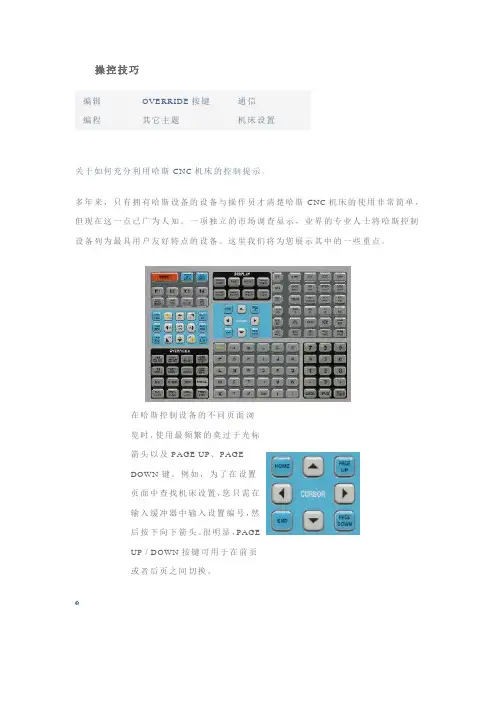
操控技巧编辑 OVERRIDE按键通信编程其它主题机床设置关于如何充分利用哈斯CNC机床的控制提示。
多年来,只有拥有哈斯设备的设备与操作员才清楚哈斯CNC机床的使用非常简单,但现在这一点已广为人知。
一项独立的市场调查显示,业界的专业人士将哈斯控制友好特点的设备。
这里我们将为您展示其中的一些重点。
设备列为最具用户览时,使用最频繁的莫过于光标箭头以及PAGE UP、PAGEDOWN键。
例如,为了在设置页面中查找机床设置,您只需在输入缓冲器中输入设置编号,然后按下向下箭头。
很明显,PAGEUP / DOWN按键可用于在前页或者后页之间切换。
∙PRGRM页面显示当前(活动)程序。
∙POSIT显示4种不同的位置页面,以显示真实定位以及参考定位。
∙轻松管理刀具、工件以及磨损坐标。
∙CURNT COMDS页面中的上/下页按键可显示完整的机床信息列表,包括活动的程序。
∙机床通过ALARM页面将信息发送给操作员。
∙您可将自己的信息公布在MESGS页面上。
∙哈斯服务技术人员使用―参数及诊断‖页面。
∙SETNG页面列出机床设置(可根据需要进行更改),GRAPHICS页面可用于避免碰撞。
∙HELP/CALC页面可提供解答。
PRGM/CONVRS页面程序检查-在PRGRM页面中,程序检查功能可通过光标浏览,在显示屏幕右侧查看活Array动的程序,还可在屏幕左侧查看该程序的运行情况。
要打开程序检查功能,按下F4即可(必须在MEM模式中)。
背景编辑-该功能可用于从PRGRM页面中,在程序运行时编辑程序(在MEM模式中)。
输入您希望编辑的程序编号(Onnnnn)并按下F4。
此后,您可对现有程序、新程序甚至正在运行的程序执行简单的编辑(插入、更改、删除以及撤消)。
但是,对正在运行的程序进行编辑只有在使用M30或复位功能结束程序循环后才可生效。
位置页面DIST-TO-GO页面上的Quick Zero –您可使用Distance To Go屏幕快速归零位置页面,以便执行参考运动。
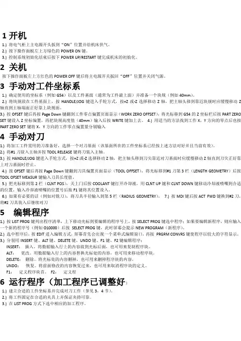
1开机1.) 将电气柜上主电源开头扳到“ON”位置并给机床供气。
2.) 按下操作面板左上方绿色的POWER ON键。
3.) 控制系统初始化结束后按下POWER UP/RESTART键完成机床的初始化。
2 关机按下操作面板左上方红色的POWER OFF键后将主电源开关扳回“OFF”位置并关闭气源。
3 手动对工件坐标系1.) 确定使用的坐标系(例如G54)以及工件基面(通常为工件最上面)并准备一个块规(例如40mm)。
2.) 将块规放在工件基面上,按HANDLE/JOG键进入手轮方式,按+Z或-Z选择移动Z轴,把主轴头移到靠近块规时应缓慢移动Z 轴直到主轴端面正好靠上块规面。
3.) 按OFSET键后再按Page Down键翻到工件零点偏置页面显示(WORK ZERO OFFSET),将光标移到G54的Z坐标栏后按PART ZERO SET键设入Z坐标偏置,再把块规高度值(40mm)输入后按WRITE键加上去。
4.) 用适当的方法找到工作X,Y方向的零点后也按PART ZERO SET键将X,Y方向的工作零点偏置量分别输入4 手动对刀1.) 将加工工件需用的刀准备好,选择一个对刀基面(该基面所在的工件坐标系已经按上述方法对好并且当前有效)。
2.) 将#1刀放入主轴并按TOOL RELEASE键将刀装入主轴。
3.) 按HANDLE/JOG键进入手轮方式,按+Z或-Z选择移动Z轴,把主轴头移到刀尖靠近对刀基面时应缓慢移动Z轴直到刀尖正好靠上对刀基面时停止。
4.) 按OFSET键后再按Page Down键翻到刀具偏置页面显示(TOOL OFFSET),将光标移到#1刀第3栏(LENGTH GEOMETRY)后按TOOL OFSET MEASUR键输入刀具长度值。
5.) 把光标移到第2栏(CLNT POS),关上门后按COOLANT键打开冷却液,用CLNT UP键和CLNT DOWN键移动冷却液喷嘴到合适的位置,输入冷却液喷嘴的位置号后按F1键将其位置设入。
哈斯自动数控机械(上海)有限公司数控车削加工中心ST-
20Y
无
【期刊名称】《现代制造》
【年(卷),期】2014(000)014
【摘要】在同一台机床上对复杂的工件进行车、铣加工及执行多种加工操作能够
增加产最,减少人工操作、提高精度。
因此,哈斯本次展会重点展出的明星产品-
配备了Y轴、能够进行偏心铣削、钻孔和攻螺纹加工的数控车削加工中心ST-20Y。
其宽裕的Y轴行程,结合高扭矩动力刀以及C轴运动,可进行单一设定执行多重
操作,
【总页数】1页(P56-56)
【作者】无
【作者单位】不详
【正文语种】中文
【中图分类】TG519.1
【相关文献】
1.哈斯自动数控机械(上海)有限公司 EC-400高效卧式加工中心 [J],
2.哈斯自动数控机械(上海)有限公司:ES-5-4AX卧式加工中心 [J],
3.哈斯自动数控机械(上海)有限公司VM-2高速立式模具加工中心 [J], 无
4.哈斯自动数控机械(上海)有限公司UMC-750全能型5轴立式加工中心 [J],
5.哈斯自动数控机械(上海)有限公司 UMC-750全能型立式加工中心 [J], 无因版权原因,仅展示原文概要,查看原文内容请购买。
哈斯首次推出办公室机床
佚名
【期刊名称】《现代制造》
【年(卷),期】2006(000)002
【摘要】美国哈斯自动化公司首次推出办公室铣床与办公室车床,两台机床极其紧凑,具有易移动、方便、全数控等特点。
【总页数】1页(P36)
【正文语种】中文
【中图分类】TG51
【相关文献】
1.哈斯办公室机床首次亮相 [J], 哈斯自动数控机械(上海)有限公司
2.办公室机床首次亮相——能放置在任何地方的机床 [J], 美国哈斯自动化公司
3.以“哈斯的方式” 抢滩中国市场——美国哈斯数控机床HFO落户河北石家庄[J], 余捷
4.哈斯南京HFO扬帆启航——哈斯数控机床专卖店南京店开业 [J], 杨霞
5.“办公室机床”首次亮相——能放置在任何地方的机床 [J],
因版权原因,仅展示原文概要,查看原文内容请购买。
哈斯自动化数控机械(上海)有限公司——SL系列高性能车
削中心
佚名
【期刊名称】《现代制造》
【年(卷),期】2009(000)046
【摘要】SL系列采用新型、快速液压刀塔SL-40,换刀时间比原来节省60%,可以将刀具位置偏差减少90%以上。
为了使刀塔与联轴器、齿轮箱和驱动系统更好地组装匹配,哈斯SL系列车削中心的刀塔被作为一个整体来精加工。
标准配置允许刀具在从工件缩回时同步换刀,这种特性与高速进给结合,快速换刀,将切削时间减少到一个绝对最小值,
【总页数】1页(P61)
【正文语种】中文
【中图分类】TG519.1
【相关文献】
1.哈斯中国建广给客户最贴心的服务——记哈斯自动数控机械制造(上海)有限公司开幕典礼及哈斯自动化成25周年庆典 [J], 梅峰
2.哈斯自动数控机械(上海)有限公司新一代哈斯车削中心 [J],
3.哈斯自动数控机械(上海)有限公司:VF-3系列立式加工中心 [J],
4.哈斯自动数控机械(上海)有限公司 SL-10数控车床 [J],
5.胸怀客户儒帅仁心——访哈斯自动数控机械(上海)有限公司哈斯自动数控机械制造(上海)有限公司总经理牟德华先生 [J],
因版权原因,仅展示原文概要,查看原文内容请购买。