减速式电子膨胀阀说明书
- 格式:pdf
- 大小:56.16 KB
- 文档页数:7
YK-DPF VER.1电子膨胀阀控制器技术规格书无锡云开电子科技有限公司2013年12月1、概述YK-DPF VER.1电子膨胀阀控制器专门用于中央空调系统中电子膨胀阀的开度控制,可以替代热力膨胀阀和毛细管,能达到良好的温度和制冷剂流量的控制效果,并能起到良好的节能作用。
1.1 适用范围YK-DPF VER.1电子膨胀阀控制器适用于所有5芯,6芯12V系列电子膨胀阀配套用(如三花等)。
YK-DPF VER.1电子膨胀阀控制器的控制对象是500P开度的电子膨胀阀。
1.2 主要功能特点1.2.1 多点温度检测YK-DPF VER.1电子膨胀阀控制器同时检测系统的制冷蒸发器进口温度、制热蒸发器进口温度和回气管温度。
检测的温度可以手动查询显示,当传感器损坏时,显示故障代码。
1.2.2 所有控制参数可设置YK-DPF VER.1电子膨胀阀控制器内所有与控制相关的温度参数和时间参数都可以调整,以适应不同的机组或电子膨胀阀。
1.2.3 温度和开度可显示查询YK-DPF VER.1电子膨胀阀控制器所有检测到的温度都可以被查询,电子膨胀阀的开度也可以实时查询显示。
1.2.5 手动调节功能在机组开发和调试阶段,可以通过YK-DPF VER.1电子膨胀阀控制器手动调整电子膨胀阀的开度,取得有效的试验数据。
1.3主要技术参数:1.3.1 工作电压控制器变压器:初级220V/AC 次级① 12.5V/AC频率50HZ1.3.2 工作环境工作环境温度: -10℃—+60℃储存环境温度: -20℃—+70℃相对湿度: 40%—98%1.3.3 温度传感器1#制冷蒸发器进口温度传感器(T1) 3470-502±1%1#制热蒸发器进口温度传感器(T2) 3470-502±1%1#回气管温度传感器(T3) 3470-502±1%2#制冷蒸发器进口温度传感器(T4) 3470-502±1%2#制热蒸发器进口温度传感器(T5) 3470-502±1% 2#回气管温度传感器(T6) 3470-502±1%2 控制器说明YK-DPF VER.1电子膨胀阀控制器接口说明下图是YK-DPF VER.1单路电子膨胀阀控制器的实物照片:图2.1 YK-DPF VER.1电子膨胀阀控制器接口示意图(1)电子膨胀阀接口(2)变压器接口(3)220V/AC 相线接口 (4) 220V/AC 零线接口(5) 压缩机工作输入接口(火线信号输入) (6) 四通阀工作输入接口(火线信号输入) (7)回气管温度传感器安装在蒸发器的回气管上,以下简称T 回气 (8)制热蒸发器进口温度传感器安装在蒸发器的制热进口管上,以下简称T 制热 (9)制冷蒸发器进口温度传感器安装在蒸发器的制冷进口管上,以下简称T 制冷 (10)手动减小键在手动模式下,按一次该键则电子膨胀阀开度减一。
PUNP ELECTRONICDM23螺杆机.带电子膨胀阀,电脑控制器厂家使用说明书在安装使用控制器之前,详细阅读该使用说明书!邦普电脑技术开发有限公司 2007/12/20软件功能码:X1.DM23C.TY.F40M V1.02版权所有,翻印必究目录一、DM23概述 (1)1.1、性能简介 (1)1.2、安全要求 (2)1.3、上电前的准备 (2)1.4、模块机组控制器系统配置表 (2)二、安装说明 (3)2.1、DM23C外形安装尺寸图: (3)2.2、L Y506外形安装尺寸图: (3)2.3、L Y511外形安装尺寸图: (4)2.4、蓄电池外形安装尺寸图: (4)2.5、开关电源外形安装尺寸图: (5)2.6、DM23C电源、通讯连接示意图: (6)三、流程图 (7)四、机组运行 (8)4.1、开机界面 (8)4.2、运行主界面 (9)4.3、机器设置界面 (9)4.4、用户设置界面 (9)4.5、状态查询界面 (10)4.6、历史记录界面 (10)4.7、使用说明界面 (10)4.8、故障查询界面 (11)五、厂家设置 (11)5.1、厂家参数设置 (11)5.2、使用期限 (12)5.3、系统数据复位 (12)5.4、修改厂家设置密码 (13)六、机器设置 (14)6.1、机型设置 (14)6.2、探头设置 (14)6.3、时间设置 (15)6.4、开关量定义 (17)6.5、温度界限设置 (19)6.6、温控参数设置 (20)6.7、自定义输出端口参数 (21)6.8、测量压力传感器参数设置 (21)6.9、膨胀阀参数设置 (22)6.10、膨胀阀驱动模块操作说明 (23)6.11、电流传感器参数设置 (25)6.12、初始化参数 (27)6.13、修改机器设置密码 (27)七、用户设置 (27)7.1、用户参数设置 (27)7.2、星期定时设置 (27)7.3、压缩机使用设置 (27)7.4、时间设置 (28)7.5、对比度设置 (28)7.6、画面设置 (28)7.7、选择语言 (28)7.8、触摸器校准 (28)7.9、修改用户设置密码 (28)7.10、强制动作 (28)八、控制逻辑 (29)8.1、开机操作 (29)8.2、停机操作 (29)8.3、能量调节 (29)8.4、除霜逻辑 (31)8.5、防冻逻辑 (32)8.6、外循环泵功能 (33)8.7、冷凝风机 (33)8.8、冷却塔风扇 (34)8.9、定时逻辑 (34)8.10、保护 (34)8.11、膨胀阀控制 (35)8.12、密码管理 (35)九、电子膨胀阀 (35)9.1、电子膨胀阀工作原理 (35)9.2、电子膨胀阀动作 (36)9.3、满液式蒸发器回油控制 (36)十、故障诊断 (36)10.1、故障显示 (36)10.2、故障编号以及说明 (36)十二、附录 (41)12.1、电气连接图 (41)12.1.1、风冷热泵机型 (42)12.1.2、风冷冷水机型 (43)12.1.3、水源热泵机型 (44)12.1.4、水冷冷水机型 (45)12.1.5、电子膨胀阀驱动模块.吸气过热度 (46)12.1.6、电子膨胀阀驱动模块.蒸发过热度 (47)12.1.7、电子膨胀阀驱动模块.排气过热度 (48)12.1.8、电子膨胀阀驱动模块.冷凝过冷度 (49)12.1.9、电子膨胀阀驱动模块.液位 (50)12.2版本升级说明 (51)一、DM23概述DM23系列控制器是邦普公司设计生产的一种可编程控制器,采用双微处理器技术,适用于空调领域,可据用户的需要编写程序,使空调系统运行在最佳的状态。
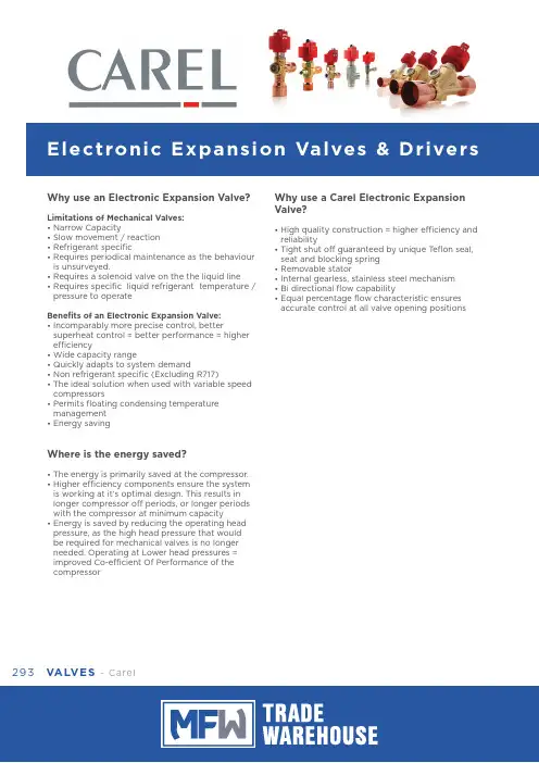
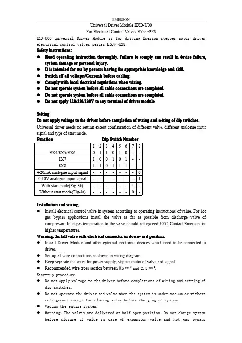
293VALVES - CarelWhy use an Electronic Expansion Valve?Limitations of Mechanical Valves:• Narrow Capacity• Slow movement / reaction • Refrigerant specific • R equires periodical maintenance as the behaviour is unsurveyed.• Requires a solenoid valve on the the liquid line • R equires specific liquid refrigerant temperature / pressure to operateBenefits of an Electronic Expansion Valve:• I ncomparably more precise control, bettersuperheat control = better performance = higher efficiency• Wide capacity range• Quickly adapts to system demand• Non refrigerant specific (Excluding R717)• T he ideal solution when used with variable speed compressors • P ermits floating condensing temperature management • Energy savingWhere is the energy saved?• The energy is primarily saved at the compressor.• H igher efficiency components ensure the system is working at it’s optimal design. This results in longer compressor off periods, or longer periods with the compressor at minimum capacity • E nergy is saved by reducing the operating head pressure, as the high head pressure that would be required for mechanical valves is no longer needed. Operating at Lower head pressures = improved Co-efficient Of Performance of the compressorWhy use a Carel Electronic Expansion Valve?• H igh quality construction = higher efficiency and reliability • T ight shut off guaranteed by unique T eflon seal, seat and blocking spring • Removable stator• Internal gearless, stainless steel mechanism • Bi directional flow capability • E qual percentage flow characteristic ensures accurate control at all valve opening positions294mf .au sales@mf .auCarel - VALVES With capacity ranging from 0.1 kW to2000 kW, there would be a Valve suitable to your application.Valve SizingDue to the vast range of applications and variables to consider when selecting an Expansion valve, it isHIGHL Y suggested the valve is sized correctly by a Refrigeration Engineer.Carel have developed an online sizing tool. It isfreely accessibly but will require a login registration.Go to: /group/exv-sistema/home The virtual sizing console is called ‘Exv Lab’The Application295VALVES- CarelAccessories for EV Series296mf .au sales@mf .auCarel - VALVES EVD Evolution DriversAccessories for EVD DriversEVD Evolution KitsmponentsT o use an electronic valve, the valve will require a valve driver. The Carel range is ever expanding, the primary control to manage an Electronic valve is the EVD Evolution Driver.Other controllers include Ultracella and MPXPRO.Features of the EVD EVO Driver• Superheat management with auxiliary high pressure, low pressure and low superheat protection • Simple start up with just 4 parameters (Refrigerant, application, valve type and sensors)• Ultracap back up integration • Twin version option• Adaptive control algorithms • Digital Scroll suitable• Visual help visible on displayEVD drivers require a pressure transducer and cable, and a strap-on NTC sensorThe kits include a driver, ratiometric pressuretransducer and cable, valve cable and temperature sensor. The display is to be purchased separately.297VALVES - CarelDisplay ModePlease NotePlease read these instructions in conjunction with the parameter list and the installationmanual. It is recommended that the controllers be programmed before connecting or activating the plant to be controlled.An automatic setup procedure appears on the EVD Evo display at startup. The 4 main parameters need to be configured and confirmed to start the driver operation.Installation manual:+0302205EN EVD Evolution+0302206EN EVD Evolution TwinT echnical leaflets:+050004150 EVD Evolution and graphic display +050004155 USB-tLan converter for EVD Evo+050004165 Battery charge and battery for EVD Evo +050004170 EVD Evolution Twin and graphic displayLiterature AvailableMeaning of the LEDsService Parameters (A)Manufacturer Parameters (C)A) PRESS Esc one or more times to switch to the standarvd display PRESS ARROW 'UP' or 'DOWN' to display a graph, the wiring diagram and the main valuesPRESS 'ESC' to exit the display modeA) PRESS Esc one or more times to switch to the standard display B) PRESS 'Prg' to display the password screenC) PRESS 'ENTER' and enter the password '22' then PRESS 'ENTER'D) PRESS ARROW 'UP' or 'DOWN' until reaching the parameter to be modifiedE) PRESS 'ENTER' to access the value. Then PRESS ARROW 'UP' or 'DOWN' to increase or decrease the valueG) PRESS 'ENTER' to save the value Repeat the operations D to G to set other parametersH) PRESS 'Esc' to permanently save the new valuesI) Follow the points A) to C) from the service parameters access with password '66' then PRESS 'ENTER'J) PRESS ARROW 'UP' or 'DOWN' until reaching the category wanted K) PRESS 'ENTER' to access the first parameter in the category. Then PRESS ARROW 'UP' or 'DOWN' until reaching the parameter to be modifiedL) PRESS 'ENTER' to access the value. Then PRESS ARROW 'UP' or 'DOWN' to increase or decrease the valueM) PRESS 'ENTER' to save the value Repeat the operations K to M to set other parametersN) PRESS 'Esc' to permanently savethe new values298mf .au sales@mf .auCarel - VALVESEVD Summary of Operating Parameters299VALVES- CarelKey for Diagram (Electronic Expansion Valves & Drivers)Wiring with Ultracap module EVD0000UC01,3,2,4aa*The transformer size depends on the driver used:For CAREL valves driver use a 20VA transformer.For universal valves driver use a 40VA transformer.Notes on earthingThe shield of the valve cable MUST be earthed.We recommend the use of 1 transformer per driver.Respect the polarity G – G0: If earthing thesecondary of the transformer (24V), only earth G0.Due to the tight shut off of the Carel Electronic Valve, there is no need for a solenoid when an Ultracap power backup module is installed.This device provides enough power to drive the valve shut in the event there is power loss.*The order of the valve connection cable is 1 3 2 4300mf .au sales@mf .auCarel - VALVES。

E2V System/E2V电子膨胀阀系统用户手册User manual重要提示安装和操作本产品前,请仔细阅读本手册中的说明,以及随本产品附送的说明书中的说明。
本产品针对特定用途而设计,因此只要按照如下要求进行操作,就不会发生危险:· 请根据本手册中的说明,以及随本产品附送的说明书中的说明,进行有关的安装、操作以及维护工作。
· 相关的环境条件、运行压力和电源电压的下降幅度,应维持在说明书中规定的范围之内。
用户负责检查所述的设备特性是否与运行条件相一致。
事先未经设备制造商的授权而更改设备,或将设备另作它用,均是不恰当的。
由使用不当而导致的人身伤害和财产损失,责任由用户负全责。
注意事项:本设备的部分电气组件带电,而且有些零部件还处于压力状态中。
因此,设备的各种检修和维护工作,必须由掌握必要预防措施的专家和技术人员进行。
在拆装内部部件之前,应断开电源,将压力调整至周围环境压力的水平。
零部件弃置E 2V 阀是由金属和塑料部件制成。
必须依照当地现行的废物弃置法规,进行弃置。
IMPORTANT WARNINGSBEFORE INSTALLING OR OPERATING ON THE APPLIANCE,CAREFULLY READ THE INSTRUCTIONS IN THIS MANUAL AND ONTHE INSTRUCTION SHEET ENCLOSED WITH THE PRODUCT.This equipment has been designed to operate without risks forthe specific purpose, as long as:• the installation, operation and maintenance are performed accordingto the instructions in this manual and on the instruction sheetenclosed with the product;• the environmental conditions, the operating pressure and the powersupply voltages fall within the values specified on the instruction sheet.The user is responsible for checking that the characteristics describedare compatible with the operating conditions.Any other use or changes which have not been previously authorisedby the manufacturer, are considered improper.Liability for injures or damage caused by improper use lies exclusively with the user.Note that some electrical components of this instrument are live andsome parts are under pressure, thus all the service or maintenanceoperations must be performed by expert and skilled personnel only,aware of the necessary precautions.Before accessing the internal parts, disconnect the power supply andrestore the pressure to that of the surrounding environment. Disposal of the partsThe E2V valves are made up of metal and plastic parts. must be disposed of according to the local legislation in force on waste disposal.我们希望节省您的时间和金钱!We wish to save you time and money! We can assure you that the thorough reading of this manual will guarantee correct installation and safe use of the product described.我们确信彻底阅读本手册是正确安装和安全 使用本设备的保证。
表号:LJIII0200357
生效期:2011-1-28
文件名称:电子膨胀阀设计选型指导书
文件编号:SJZD20110019
山东朗进科技股份有限公司
2022年4月
产品型号、名称
电子膨胀阀
设计选型指导书
SJZD20110019
共13 页第 3 页
膨胀阀可靠开启时,膨胀阀进出口间的最大压力差。
四、原理介绍
4.1定义、功能
电子膨胀阀是一种节流元器件,可以按预设的程序控制步进电机的运转,由电机转子直接驱动阀针,改变阀口的流通面积,从而实现制冷剂流量控制的执行器件。
电子膨胀阀是由电子电路进行控制的膨胀阀,它是变频制冷空调设备中的关键部件。
电子膨胀阀有其他膨胀阀无法比拟的优点。
它的流量控制范围大,动作迅速,调节精细,动作稳定,可以使制冷剂往、返两个方向流动。
在变频式制冷空调设备中,压缩机由变频电动机拖动,电动机的转速可以根据室内制冷量的需要而连续变化,最终压缩机的制冷量达到连续变化的自动控制,为配合制冷量的连续变化,采用电子膨胀阀与变频式压缩机匹配使用。
由于电子膨胀阀能够根据微电脑的指令,迅速调节阀的开启度,快速控制制冷剂的流量,可减小房间室内的温差,因而能够增强空调的舒适程度,又可最大限度的节能。
4.2 电子膨胀阀基本原理(图示)
电子膨胀阀根据电机的驱动方式分为减速型电子膨胀阀和直动型电子膨胀阀两大类。
减速型电子膨胀阀,电子膨胀阀线圈和阀体为一体,当脉冲电机通过减速齿轮组传递动力,与波纹管一起对阀针升程进行调节。
由于齿轮的减速作用,大大增加了输出转
5.4 根据系统的匹配需要选择合适的流量特性。

制冷空调用直动式电子膨胀阀产品说明书上海俊乐制冷自控元件有限公司2003年3月1 适用范围本说明书介绍了俊乐公司直动式电子膨胀阀的型式、基本参数、主要技术要求和使用注意事项。
2 产品型号规格2.1 产品型号表示方法2.2 产品规格推荐配用机型型号(R22,制冷量kW)DPF1.5 2.0~3.5DPF1.6 2.0~3.6DPF1.8 2.5~5.0DPF2.0 3.5~6.0DPF2.2 5.0~8.0DPF2.4 6.0~10.0DPF3.0 8.0~15.03 基本参数3.1 适用环境温度:-30℃~+60℃。
3.2 适用介质温度:-30℃~+70℃。
3.3 适用环境湿度:95%RH以下。
3.4 安装方向:线圈在上,阀体竖直前后左右±15°以内。
3.5 使用压力:0 MPa~2.95MPa。
3.6 流动方向:正反皆可。
3.7 线圈绝缘等级:E级。
3.8 驱动方式:四相永磁型步进电机,直动式,电压:DC12V±15%;励磁方式:1-2相励磁;励磁频率:30~90PPS。
3.9 驱动电流:口径2.4mm以下的膨胀阀,线圈电流小于0.25A;口径2.4mm以上(包括2.4mm)、3.0mm以下(包括3.0mm)的膨胀阀,线圈电流小于0.35A;3.10 阀开度:0为全闭;500为全开。
3.11 线圈接线方式及励磁顺序黄红 蓝动作顺序:1→2→3→4→5→6→7→8 关阀;8→7→6→5→4→3→2→1 开阀。
4 主要技术要求 4.1 外形尺寸及外观质量 膨胀阀的外形及安装尺寸应符合规定程序批准的图样要求;外观应光洁平整,零部件无损伤,标志清晰。
4.2 气密性 膨胀阀在3.3MPa的气体(干燥氮气)压力下,应无渗漏。
4.3 耐压强度 膨胀阀应能承受4.42MPa的压力,不应有泄漏及变形现象。
4.4 破环压力 膨胀阀应能承受液压12MPa,1min的破坏压力试验,不应破裂。
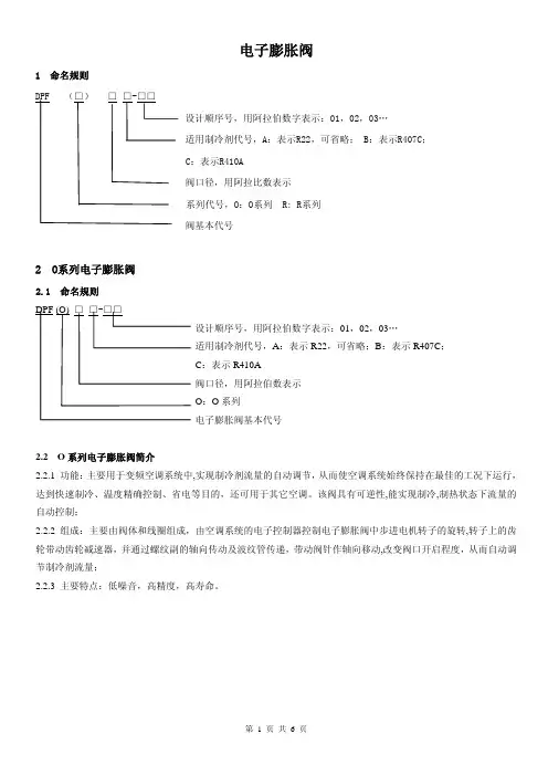
电子膨胀阀1 命名规则设计顺序号,用阿拉伯数字表示:01,02,03…适用制冷剂代号,A:表示R22,可省略;B:表示R407C;C:表示R410A阀口径,用阿拉伯数表示O:O系列电子膨胀阀基本代号2.2 O系列电子膨胀阀简介2.2.1 功能:主要用于变频空调系统中,实现制冷剂流量的自动调节,从而使空调系统始终保持在最佳的工况下运行,达到快速制冷、温度精确控制、省电等目的,还可用于其它空调。
该阀具有可逆性,能实现制冷,制热状态下流量的自动控制;2.2.2 组成:主要由阀体和线圈组成,由空调系统的电子控制器控制电子膨胀阀中步进电机转子的旋转,转子上的齿轮带动齿轮减速器,并通过螺纹副的轴向传动及波纹管传递,带动阀针作轴向移动,改变阀口开启程度,从而自动调节制冷剂流量;2.2.3 主要特点:低噪音,高精度,高寿命。
2.3 外观图2.4 基本参数规格型号 通径(mm )R22名义容量Kw (U.S.R.T ) 全开脉冲最大动作压差 阀口泄露 最高使用压力 线圈温升噪音 寿命DPF (O )1.3 1.3 5.28(1.5) DPF (O )2.0 2.0 8.8(2.5) DPF (O )2.4 2.4 10.56(3.0) DPF (O )3.2 3.2 14.1(4.0)DPF (O )3.2 3.2 17.6(5.0)DPF (O )4.0 4.0 21.2(6.0) DPF (O )5.2 5.2 28.1(8.0)DPF (O )6.4 6.4 35.5(10.0)2000 2.26MPa(R22)2.48MPa (R407C )3.43MPa(R410A)≤600mL/min(阀口径≤Φ2.4)≤1000mL/min (阀口径>Φ2.4) 3.0MPa(R22) 3.3MPa(R407C)4.2MPa(R410A) ≤60K ≤45dB(A)(300mm)5万次2.5 工作条件2.5.1 适用制冷剂:R22、R407C 、R410A ; 2.5.2 介质温度:-30℃~+70℃(通电率50%以下); 2.5.3 环境温度:-30℃~+60℃(通电率50%以下); 2.5.4 相对湿度:95%以下; 2.5.5 额定电压:DC12V ,矩形波;2.5.6 电压变化:额定电压的90%~110%范围以内; 2.5.7 驱动方式:4相步进电机驱动; 2.5.8 励磁方式:2-2相励磁;2.5.9 励磁速度:100PPS~250PPS (开阀励磁速度≤闭阀励磁速度); 2.5.10冷媒流动方向:正反皆可;2.5.11安装方式:阀体中轴线垂直水平面±15°。
电子膨胀阀1 命名规则设计顺序号,用阿拉伯数字表示:01, 02, 03…适用制冷剂代号, A :表示 R22,可省略; B :表示 R407C ;C :表示 R410A阀口径,用阿拉伯数表示O :O 系列电子膨胀阀基本代号2.2 O系列电子膨胀阀简介2.2.1 功能:主要用于变频空调系统中 , 实现制冷剂流量的自动调节, 从而使空调系统始终保持在最佳的工况下运行, 达到快速制冷、温度精确控制、省电等目的,还可用于其它空调。
该阀具有可逆性 , 能实现制冷 , 制热状态下流量的自动控制;2.2.2 组成:主要由阀体和线圈组成,由空调系统的电子控制器控制电子膨胀阀中步进电机转子的旋转 , 转子上的齿轮带动齿轮减速器, 并通过螺纹副的轴向传动及波纹管传递, 带动阀针作轴向移动 , 改变阀口开启程度, 从而自动调节制冷剂流量;2.2.3 主要特点:低噪音,高精度,高寿命。
2.3 外观图2.4 基本参数规格型号通径 mm 名义容量 (U.S.R.T 全开脉冲最大动作压差阀口泄露最高使用压力线圈温升噪音寿命DPF (O 5.28(1.5 DPF (O 8.8(2.5 DPF (O DPF (O DPF (O DPF (O DPF (O DPF (O 35.5(10.02000 2.26MPa(R22(R407C 3.43MPa(R410A≤600mL/min(阀口径≤Φ2.4≤1000mL/min (阀口径>Φ2.4≤60K ≤ 45dB(A(300mm5万次2.5 工作条件2.5.1 适用制冷剂:R22、 R407C 、 R410A ; 2.5.2 介质温度:-30℃~+70℃ (通电率50%以下 ; 2.5.3 环境温度:-30℃~+60℃ (通电率 50%以下 ; 2.5.4 相对湿度:95%以下;2.5.5 额定电压:DC12V ,矩形波;2.5.6 电压变化:额定电压的 90%~110%范围以内; 2.5.7 驱动方式:4相步进电机驱动; 2.5.8 励磁方式:2-2相励磁;2.5.9 励磁速度:100PPS~250PPS(开阀励磁速度≤闭阀励磁速度 ; 2.5.10冷媒流动方向:正反皆可;2.5.11安装方式:阀体中轴线垂直水平面±15°。
wtexv10电子膨胀阀控制器说明书Wtexv10电子膨胀阀控制器说明书一、产品简介Wtexv10电子膨胀阀控制器是一款功能强大且操作简单的产品,它由分布式I/O技术来实现,具有多通道输出控制功能,可以在管线上连接多个电子膨胀阀。
该产品主要用于控制电子膨胀阀的开关关闭,以调节水系统的压力值。
二、特性1、触摸键、控制箱和电子膨胀阀之间均采用低功耗红外通讯技术,有效减少电源消耗;2、采用高精度、高可靠性的温度湿度传感器,可检测气候条件;3、支持标准压力表,实现连续可调压力;4、采用真彩色液晶显示屏,实时显示压力值与温度湿度;5、采用快速反应功能,精确控制电子膨胀阀的开关;6、支持物联网技术,实现远程监控管网的压力状态;7、外壳采用坚固耐用的塑料,具有防水、防护、耐高低温特性;8、可以在同一管道上安装多个电子膨胀阀,有助于提高管网运行效率;9、支持RS485和RS232两种通讯协议,让操作更加方便。
三、安装说明1、首先将电子膨胀阀控制器的外壳面向上放置,铰链的螺钉松开,将控制器和电子膨胀阀接连在一起,使用螺栓和螺母固定;2、将控制器放置固定的位置,然后将铰链的螺钉紧固;3、把电源线连接到插座,插入电源;4、将控制器箱体和控制器连接在一起,并将电源线插入控制器箱体插座;5、按照触摸屏上的操作说明,设置压力参数;6、将触摸键和控制箱连接起来,安装完成;7、把电源开关打开,看到电子膨胀阀是否亮起来。
四、使用说明1、打开电源时,按下触摸键,将屏幕上的参数设置为需要的值,如工作压力、保护压力、迟滞压力等;2、观察控制箱上的控制灯,设置初始压力后,触摸键打开下拉菜单;3、检查电子膨胀阀的开关,电源处于开启状态时,电子膨胀阀自动打开,当达到设定的阀门关闭压力时,电子膨胀阀关闭;4、通过设置正确的参数,保证水系统在一定范围内保持良好的状态;5、当电子膨胀阀出现故障时,检查控制箱上的LED指示灯,迅速更换或者维修;6、当电源要关闭时,先关闭电子膨胀阀,再关闭电源。
表号:LJIII0200357生效期:2011-1-28文件名称:电子膨胀阀设计选型指导书文件编号:SJZD20110019山东朗进科技股份有限公司2020 年5 月文件名称 设计指导书 文件编号产品型号、名称 电子膨胀阀 设计选型指导书 SJZD20110019 共 13 页 第1 页目录一、适用范围 ............................... 二、规范性引用文件......................... 2.1 参考资料 ........................... 2.2 参考标准 ........................... 三、术语 ..................................四、原理介绍 ...............................4.1 定义、功能 ......................... 4.2 电子膨胀阀基本原理(图示) ......... 五、设计选型步骤 ...........................设计原则 .......................... 确定电子膨胀阀的驱动方式 .......... 确定电子膨胀阀的口径 .............. 根据系统的匹配需要选择合适的流量特性22 2 35.1 5.2 5.3 5.4六、电子膨胀阀设计、安装注意事项6.1 电子膨胀阀设计注意事项 ..6.2 电子膨胀阀安装注意事项 .. 七、电子膨胀阀常见故障分析 .............7.1 电子膨胀阀打不开、关不死 7.2 电子膨胀阀产生异常音的事例. 8 10 111112电子膨胀阀设计选型指导书、适用范围1. 本设计选型指导书,适用于轨道空调类用电子膨胀阀的选型。
2. 本设计选型指导书涉及到电子膨胀阀的分类、电子膨胀阀的选型、使用设计标准、安装生产工艺及前期在使用过程中出现的问题。
室内电子膨胀阀开度控制规格书4.1停止中4.1.1开关OFF停止中4.1.2冷房温控器OFF停止中4.1.3暖房温控器OFF停止中4.2冷房运转中4.2.1始动控制中4.2.1.1温控器ON的机组4.2.1.2温控器OFF的机组4.2.1.3停止的机组4.2.2正常运转中4.2.2.1温控器ON的机组4.2.2.2温控器OFF的机组4.2.2.3停止的机组4.2.3正常运转中(控制)4.2.3.1室数变化中4.2.3.2压缩机台数增加时4.3暖房运转中4.3.1启动控制中4.3.1.1温控器ON的机组4.3.1.2温控器OFF的机组4.3.1.3停止的机组4.3.2始动控制中4.3.2.1温控器ON的机组4.3.2.2温控器OFF的机组4.3.2.3停止的机组4.3.3正常控制中4.3.3.1温控器ON的机组4.3.3.2温控器OFF的机组4.3.3.3停止的机组4.3.4正常控制中(控制)4.3.4.1室数变化时4.4除霜运转中4.4.1温控器ON的机组4.4.2温控器OFF的机组4.4.3停止的机组4.5室内膨胀阀保护控制4.5.1Ps保护控制4.5.2回油控制4.5.3膨胀阀开度防止控制4.1停止中4.1.1开关OFF停止中冷房时:零点控制后EVI=40 pls暖房时:(1)四通阀OFF前EVI(n)=105 pls(2)四通阀OFF后EVI(n)=40 pls4.1.2 冷房温控器OFF停止中零点控制后EVI=40 pls4.1.3暖房温控器OFF停止中EVI=4.2冷房运转中4.2.1始动控制中4.2.1.1温控器ON的机组EVIstart=EVIHP×(1/2)×(kmto+2)×KEVI(130≤EVIstart≤2000)(1)合计室内机运转容量∑K HP_on(k)<2HP时●室数增加时kmto=0KEVI=1●冷启动时kmto=0KEVI=3.0/室外HP×Ft/{∑K HP_on(k)×15} (1≤KEVI≤1.3)●热启动时kmto=(1/20)×(25-To)(0≤kmto≤a)(2)合计室内机运转容量∑K HP_on(k)≥2HP时●室数增加时kmto=0KEVI=1●冷启动时kmto=0KEVI=3.0/室外HP×Ft/{∑K HP_on(k)×15} (0.4≤KEVI≤1.2)●热启动时kmto=(1/20)×(25-To)(0≤kmto≤1.0)KEVI=1.1×Ft/{∑K HP_on(k)×15} (0.6≤KEVI≤2)Ft(n):始动后的压缩机指令频率(Hz)HP_on:运转室内机的容量(HP)(3)前馈控制进行PID控制前,一直进行前馈控制。