模拟量输入模块AI561
- 格式:doc
- 大小:241.00 KB
- 文档页数:12

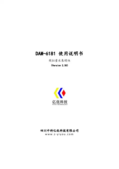
DAM-6181使用说明书模拟量采集模块(Version2.30)四川中科亿优科技有限公司w w w.z-y i y o u.c o m目录1产品简介 (1)1.1产品概述 (1)1.2技术参数 (1)1.3产品出厂默认设置 (1)1.4产品外形 (2)2接线说明 (2)2.1模块端口示意图 (2)2.2接口定义 (3)2.3供电电源 (3)2.4通信接口 (3)2.4.1RS485连接 (4)2.4.2RS232连接 (4)2.5电压模拟量输入接线 (5)3通信说明 (5)3.1主从模式 (5)3.2通信参数 (5)3.2.1通信地址 (5)3.2.2通信速率 (6)3.3MODBUS-RTU通信协议 (5)3.3.1读寄存器状态采集数据 (6)3.3.2设置设备地址 (7)3.3.3设置波特率 (7)4配置安装 (8)4.1上位机调试说明 (8)4.2模块参数配置说明 (9)4.3指示灯说明 (9)4.4产品尺寸 (9)4.5安装方式 (10)5售后服务 (11)6免责声明 (11)6.1版权 (11)6.2修改文档的权利 (11)1、产品简介1.1产品概述DAM-6181模拟量采集模块可采集量程为0-5V/0-10V/±5V/±10V的模拟量输入信号,其他量程可以定制。
模块配置隔离RS485/隔离RS232通讯接口,采用工业标准Modbus-RTU 通信协议,可与组态软件、PLC、工业触控屏等进行组网使用,广泛应用于工业现场设备的信号采集、监控等。
电源端口和通信端口都具有防浪涌,防雷击保护,能够最大限度防止工业现场的静电和浪涌冲击。
采用标准DIN35导轨安装方式,现场安装简单方便。
1.2技术参数技术参数描述输入通道2路/4路/8路模拟量输入输入类型电压输入电压量程0~5V、0~10V、±5V、±10V(其他量程可以定制)通信接口隔离RS485/隔离RS232通信协议标准Modbus-RTU波特率1200~115200bps默认参数设备地址1;9600,8,N,1分辨率16位采集精度0.1%采样频率AD采样速率1kHz;Modbus通信更新速率<10Hz工作电压DC+8~24V通信地址1~245支持设备PLC、触摸屏、组态软件等稳定性内置看门狗,防死机保护等级电源接口有防反接保护,防浪涌,防雷击工作温度-40℃~+80℃安装方式标准DIN导轨安装外形尺寸122*72*45mm1.3产品出厂默认设置产品出厂默认设置参数为:●设备地址:1;●波特率:9600bps;●MODBUS-RTU的数据通信格式:8位数据位,1位停止位,无奇偶校验位;1.4产品外形2、接线说明2.1模块端口示意图2.2接口定义端子编号端子名称说明1VCC电源输入正极2GND电源输入负端3GND接地端4485B RS485信号B-5485A RS485信号A+6GND RS485信号接地端7232T RS232发送端8232R RS232接收端9GND RS232接地端10CANL CANL端11CANH CANH端12GND接地端13AIV1第1路模拟量输入正端14GND信号地15AIV2第2路模拟量输入正端16GND信号地17AIV3第3路模拟量输入正端18GND信号地19AIV4第4路模拟量输入正端20GND信号地21AIV5第5路模拟量输入正端22GND信号地23AIV6第6路模拟量输入正端24GND信号地25AIV7第7路模拟量输入正端26GND信号地27AIV8第8路模拟量输入正端28GND信号地2.3供电电源供电电压为8~24V DC的直流电源,需要注意接口有正负之分,输入电源的最大电压为24V,注意保持电压波动在规定的范围内,超过范围可能会造成模块电路永久性损坏。
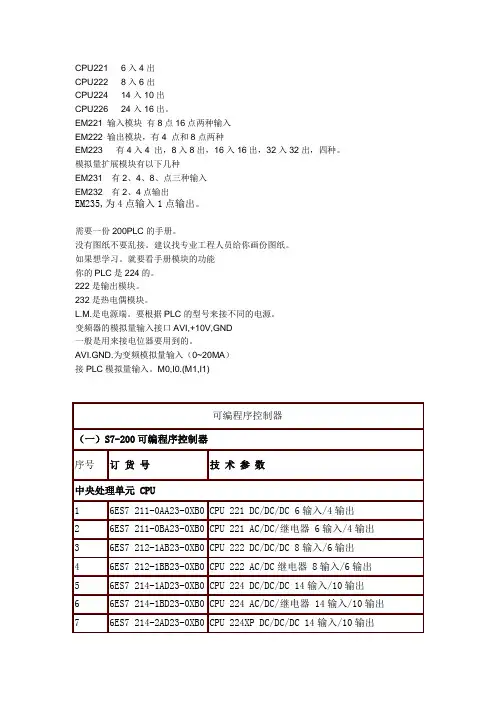
CPU221 6入4出CPU222 8入6出CPU224 14入10出CPU226 24入16出。
EM221 输入模块有8点16点两种输入EM222 输出模块,有4 点和8点两种EM223 有4入4 出,8入8出,16入16出,32入32出,四种。
模拟量扩展模块有以下几种EM231 有2、4、8、点三种输入EM232 有2、4点输出EM235,为4点输入1点输出。
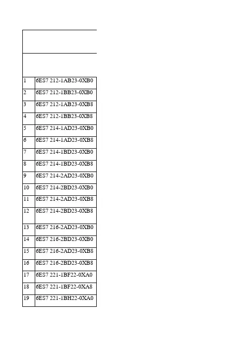
74 6AV6 545-0CA10-0AX0 TP 270-6触摸屏,彩色:256色,5.7英寸,2M 集成闪存,320×240像素75 6AV6 545-0CC10-0AX0 TP 270-10触摸屏,彩色:256色,10.4英寸,2M集成闪存,640×480像素76 6AV6 545-0AH10-0AX0 MP 270B触摸屏,6英寸77 6AV6 545-0AG10-0AX0 MP 270B触摸多功能面板,彩色:256色,10.4英寸,存储器5M,640×480像素78 6AV6 542-0AG10-0AX0 MP 270B键控多功能面板,彩色:256色,10.4英寸,存储器5M,640×480像素79 6AV6 545-0DA10-0AX0 MP370触摸多功能面板,彩色:256色,12.1英寸,800×600像素80 6AV6 542-0DA10-0AX0 MP370键控多功能面板,彩色:256色,12.1英寸,800×600像素81 6AV6 640-0DA11-0AX0 K-TP178触摸屏,蓝色液晶显示器,5.7英寸,1MB 用户内存,8MB动态RAM1.人是初学者,现在在看书。
我手上有两本书,模块连线总不一样,我一直不理解。
第一种是输入模块的1M 2M 和M端直接连起来,然后外部输入信号的端口和L+连接;第二种是1M 2M等公共端接电源后和自己那组的输入信号端口连接,M接地,L+接24V直流电源。

基本说明⚫感谢您购买了傲拓科技NA200系列可编程序控制器。
⚫本手册主要介绍NA200系列可编程序控制器的硬件特性等内容。
⚫在使用产品之前,请仔细阅读本手册,并在充分理解手册内容的前提下,进行接线。
⚫软件及编程方面的介绍,请查阅相关手册。
⚫请将本手册交付给最终用户。
用户须知⚫只有具备一定的电气知识的操作人员才可以对产品进行接线等其他操作,如有使用不明的地方,请咨询本公司的技术部门。
⚫手册等其他技术资料中所列举的示例仅供用户理解、参考用,不保证一定动作。
⚫将该产品与其他产品组合使用的时候,请确认是否符合有关规格、原则等。
⚫使用该产品时,请自行确认是否符合要求以及安全,对于本产品故障而可能引发机器故障或损失时,请自行设置后备及安全功能。
版权申明⚫本手册内容,包括文字、图表、标志、标识、商标、产品型号、软件程序、版面设计等,均受《中华人民共和国著作权法》、《中华人民共和国商标法》、《中华人民共和国专利法》及与之适用的国际公约中有关著作权、商标权、专利权或其他财产所有权法律的保护,为傲拓科技股份有限公司专属所有或持有。
⚫本手册仅供商业用户阅读、查询,在未得到傲拓科技股份有限公司特别授权的情况下,无论出于何种原因和目的,均不得用任何电子或机械方法,以任何形式复制和传递本手册的内容。
否则本公司将依法追究法律责任。
⚫我们已核对本手册中的内容、图表与所述硬件设备相符,但误差难以避免,并不能保证完全一致。
同时,我们会定期对手册的内容、图表进行检查、修改和维护,恕不另行通知。
⚫傲拓科技股份有限公司保留全部权利。
⚫手册中涉及到的其他商标或注册商标属于他们各自的拥有者。
联系方式如果您有任何关于本产品的使用问题,请与购买产品的办事处联系,也可以直接与傲拓科技公司联系。
⚫电话:(+86)************⚫传真:(+86)************⚫网址: https:///目录第一章 NA200 PLC 概述 (1)1.1 NA200 PLC的硬件组成 (1)1.2 工作方式介绍 (5)1.3 编程软件介绍 (6)1.4 快速应用指南 (7)第二章安装、拆卸与接线原则 (9)2.1 指导原则 (9)2.2 电气安全 (10)2.3 NA200小型一体化PLC及扩展模块的安装和拆卸 (11)2.4 NA200小型一体化PLC及扩展模块的尺寸结构 (14)第三章 CPU 模块 (16)3.1 外观说明 (16)3.2 CPU模块功能简述 (16)3.3 使用说明 (17)3.4 通讯功能 (18)3.5 特殊I/O接线定义 (19)3.6 高速计数输入 (21)3.7 14点CPU模块性能参数 (24)3.8 20点CPU模块性能参数 (29)3.9 24点CPU模块性能参数 (34)3.10 40点CPU模块性能参数 (39)第四章 I/O 扩展模块 (44)4.1 数字量扩展模块 (46)4.2 模拟量扩展模块 (54)4.3 通讯扩展模块 (63)A 附录订货参数 (76)B 附录扩展模块功率 (78)第一章 NA200 PLC 概述作为小型一体化PLC 产品,NA200PLC无论是独立运行,还是相互连接构成网络,均可以实现强大而复杂的控制功能。


UC630 全同步测控装置上海惠安系统控制有限公司2007年10月NOTICE OF COPYRIGHT & PROPRIETARY RIGHTS© 2007 Wescon Control (Shanghai), Inc. All rights reserved.The contents of this manual are the property of Wescon Control (Shanghai), Inc. No part of this work may be reproduced or transmitted in any form or by any means, except as permitted in written license agreement with Wescon Control (Shanghai), Inc. The information contained in this document is subject to change without notice.目 录1. 前言 (1)2. 功能特点 (1)2.1P2C双核心技术 (1)2.2全同步测量技术 (1)2.3高精确度的测量值 (1)2.4模块化结构,组态方式灵活 (1)2.5开放式软件平台 (1)2.6强大的通信能力 (1)2.7配置灵活,容量大 (2)2.8多重防误动措施 (2)2.9大容量输出继电器 (2)2.10先进的同期功能 (2)2.11方便的远程维护 (2)3. 组成与结构 (3)3.1主模块(M AIN M ODULE) (3)3.2I/O模块(DIOM M ODULE) (4)3.3电源模块 (5)3.4机箱结构 (5)4. 功能描述 (6)4.1交流采样模块功能(AC) (6)4.2直流模拟量输入模块功能(AI) (7)4.3遥信输入模块功能(DI) (8)4.4遥控输出模块功能(DO) (9)4.5模拟量输出模块功能(AO) (9)4.6通信功能 (10)4.7显示功能 (10)4.8电源功能 (11)4.9其他功能 (11)5. 测量与计算功能 (12)5.1频率 (12)5.2相角 (12)5.3幅值 (12)5.4电功率 (12)5.563次谐波 (12)5.6电度 (13)5.7总谐波畸变 (13)5.8不平衡率 (13)5.9模拟量报警 (13)5.10软件应用 (13)5.11同期功能 (14)5.12动态母线切换功能 (14)5.13遥信输入(DI) (14)5.14遥控输出(DO) (15)5.15模拟量输入(AI) (15)5.16对时功能 (15)5.17虚拟DI(P SEUDO DI)功能 (15)6. 物理特性 (16)1. 前言UC630全同步测控装置是美国WESCON集团针对数字化变电站测控系统,采用全同步测量和P2C TM的双核心技术,在国外设计、制造的产品。
油库自动化控制系统设计报告姓名:鲁金明班级:油气1201学院:能动学院一,研究背景目前,我国的油库罐区自动化监控与国外相比,总体水平较低。
罐数据还主要依靠人工测量、读取和录入;工艺生产很多还是人工开阀、手动控泵。
系统不仅存在监控不及时、人为误差大,还有随意性强、可靠性不高等缺点,因此,很多油库罐区都在进行以摆脱传统监控方式、作业方法,建立便捷、先进、可靠的监控系统为目的的自动化改造。
油库储油罐区是油料保障的重要储存基地,具有分布空间范围广、安全防爆要求高、监控点多、布线复杂,自动化系统的水平和垂直集成难度大的特点。
围绕储油罐区自动监测、计量和管理,采用先进测控与管理技术,设计储油罐区监测控制与数据采集系统,改善油罐测量劳动强度大、作业环境差、管理手段落后的现状,已成为目前油库自动化建设的一项重要内容。
实时、准确、可靠、经济地采集点多面广的储油罐监控信息,实现大范围的数据共享;基于多参数实时数据,进行智能分析、处理,进一步提高计量精度;基于监控信息及数据,进行储油罐区油料平衡分析,提高储油罐区安全管理的智能化水平等。
油库罐区自动化监控系统运用现代信息化、自动化技术,方便、快捷地了解现场设备实时运行情况及历史生产信息,为生产调度决策提供可靠的数据依据;同时还能迅速、及时地对现场设备进行有效控制,从而提高作业效率。
二,系统目标1,实现对储油罐的液位、温度、压力等数据的全方位实时监测;2,实现罐区泵房油泵运行工况实时监测,并对其中的出口油泵实行点动控制操作以及油料发放实行远程联动控制操作; 3,实现罐区油料收发业务管理的网上作业,并与监控服务器组成罐区油库综合管理系统局域网;4,实现筑罐区电视监控系统。
三,系统构成与技术简介1 系统构成油库罐区监控自动化系统由采集控制层和监控计量层通过现场总线连接而成,监控计量层通过服务器与以太网相连。
油库罐区监控自动化系统,主要监测和控制的设备为:储油罐、油泵、管道、油阀和油料计量设备。
DATA SHEETDC561Digital Input/Output module1 Ordering dataPart no.DescriptionProduct life cycle phase *)1TNE 968 902 R2001DC561, digital input/output module,16 configurable inputs/outputs, transistor output, interfast connectorClassic *) Modules in lifecycle Classic are available from stock but not recommended for planning and commissioning of new installations.Ordering data2DimensionsThe dimensions are in mm and in brackets in inch.3 Technical dataThe System Data of AC500-eCo apply Ä Chapter 4 “System data AC500-eCo” on page 5Only additional details are therefore documented below.Parameter Value Process voltage UPConnections Terminals 17 and 19 for UP (+24 V DC); terminals 18 and 20 for ZP (0 V) Rated value24 V DCCurrent consumption via UP terminal 10 mA + 0.1 A per output (max.) Max. ripple 5 %Inrush current0.000001 A 2s Protection against reversed voltage YesProtection fuse on UPRecommended; the outputs must be protected by an 1 A fast-acting fuse Current consumption from 24 V DC power supply at the L+/UP and M/ZP terminals of the CPU/communication interface module Ca. 10 mAGalvanic isolationYes, between the input/output group and the rest of the moduleTechnical dataParameter ValueIsolated groups 1 group for 16 channels Surge voltage (max.)35 V DC for 0.5 s Max. power dissipation within the module On request Input data length 2 bytes Output data length 2 bytes WeightCa. 115 gMounting position Horizontal or verticalCoolingThe natural convection cooling must not be hin-dered by cable ducts or other parts in the switch-gear cabinet.No effects of multiple overloads on isolated multi-channel modules occur, as every channel is pro-tected individually by an external fuse.3.1 Technical data of the digital inputs/outputs if used as inputsParameterValueNumber of channels per module 16 configurable inputs (24 V DC)Distribution of the channels into groups 1 (16 channels per group)Connections of the channels C0 to C15Terminals 1 to 16Reference potential for the channels C0 to C15Terminals 18 and 20 (negative pole of the process voltage, name ZP)Indication of the input signals1 yellow LED per channel; the LED is ON when the input signal is high (signal 1). The module is powered via the I/O bus.Input type according to EN 61131-2Type 1 sink Input signal range +24 V DC Signal 0-3 V...+5 V Undefined signal +5 V...+15 VSignal 1+15 V...+30 V Ripple with signal 0-3 V...+5 V Ripple with signal 1+15 V...+30 V Input current per channelInput voltage +24 V Typ. 5 mA Input voltage +5 V Typ. 1 mA Input voltage +15 V > 2.5 mAInput voltage +30 V< 8 mA Max. permissible leakage current (at 2-wire proximity switches) 1 mA Input delay (0->1 or 1->0)Typ. 8 ms Max. cable lengthNo effects of multiple over-loadsTechnical data of the digital inputs/outputs if used as inputsParameter ValueShielded500 mUnshielded300 m3.2 Technical data of the digital inputs/outputs if used as outputsParameter ValueNumber of channels per module16 configurable transistor outputsDistribution of the channels into groups 1 (16 channels per group)Connections of the channels C0 to C15Terminals 1 to 16Reference potential for the channels C0 to C15Terminals 18 and 20 (negative pole of theprocess voltage, signal name ZP)Common power supply voltage Terminals 17 and 19 (positive pole of the processvoltage, signal name UP)Indication of the input signals 1 yellow LED per channel; the LED is ON whenthe input signal is high (signal 1). The module ispowered via the I/O bus.Way of operation Non-latching typeOutput voltage at signal 1UP -0.3 V at max. currentOutput delay (max. at rated load)0 to 150 µs1 to 0200 µsOutput currentRated current per channel (max.)0.1 A at UP 24 V DCRated current per group (max.) 1.6 ARated current (all channels together, max.) 1.6 ALamp load (max.)Not applicableMax. leakage current with signal 0< 0.5 mAOutput type Non-protectedProtection type External fuse on each channelRated protection fuse (for each channel) 1 A fastDemagnetization when inductive loads are switched off Must be performed externally according to load specificationSwitching frequencyWith inductive loads Max. 0.5 Hz Short-circuit-proof / overload-proof NoOverload message NoOutput current limitation NoResistance to feedback against 24 V DC sig-nalsYesConnection of 2 outputs in parallel Not possibleMax. cable lengthTechnical data of the digital inputs/outputs if used as outputsParameter Value Shielded 500 mUnshielded150 m4 System data AC500-eCo4.1 Environmental conditionsTable 1: Process and supply voltagesParameter Value 24 V DCVoltage24 V (-15 %, +20 %)Protection against reverse polarity Yes 24 V ACVoltage 24 V (-15 %, +10 %)Frequency 50/60 Hz (-6 %, +4 %)100 V ACVoltage 100 V (-15 %, +10 %)Frequency 50/60 Hz (-6 %, +4 %)230 VACVoltage 230 V (-15 %, +10 %)Frequency50/60 Hz (-6 %, +4 %)100...240 V AC wide-range supplyVoltage 100 V...240 V (-15 %, +10 %)Frequency 50/60 Hz (-6 %, +4 %)Allowed interruptions of power supply, according to EN 61131-2DC supply Interruption < 10 ms, time between 2 interruptions >1 s, PS2AC supplyInterruption < 0.5 periods, time between 2 interrup-tions > 1 sNOTICE!Exceeding the maximum power supply voltage (> 30 V DC) for process or supply voltages could lead to unrecoverable damage of the system. The system might be destroyed.Parameter Value TemperatureOperating0 °C...+60 °C (horizontal mounting of modules)0 °C...+40 °C (vertical mounting of modules and output load reduced to 50 % per group)Storage -40 °C...+70 °CTransport-40 °C...+70 °CSystem data AC500-eCo Environmental conditionsParameter ValueHumidity Max. 95 %, without condensationAir pressureOperating> 800 hPa / < 2000 mStorage> 660 hPa / < 3500 m4.2 Creepage distances and clearancesThe creepage distances and clearances meet the requirements of the overvoltage category II, pollu-tion degree 2.4.3 Insulation test voltages, routine testParameter Value200 V...240 V circuits againstother circuitry2500 V 1.2/50 µs100 V...127 V circuits againstother circuitry1500 V 1.2/50 µs100 V...240 V circuits againstother circuitry2500 V 1.2/50 µs24 V circuits (supply, 24 Vinputs/outputs, analog inputs/outputs ), if they are galvanicallyisolated against other circuitry500 V 1.2/50 µsCOM interfaces, galvanicallyisolated500 V 1.2/50 µsCOM interfaces, electrically notisolatedNot applicable Not applicableFBP interface500 V 1.2/50 µsEthernet500 V 1.2/50 µsARCNET500 V 1.2/50 µs200 V... 240 V circuits againstother circuitry1350 V AC 2 s100 V circuits against other cir-cuitry820 V AC 2 s100 V...240 V circuits againstother circuitry1350 V AC 2 s24 V circuits (supply, 24 Vinputs/outputs, analog inputs/outputs), if they are galvanicallyisolated against other circuitry350 V AC 2 sCOM interfaces, galvanically isolated 350 V AC 2 sAccording to EN61131-2Insulation test voltages, routine testParameterValue COM interfaces, electrically not isolated Not applicableNot applicable FBP interface 350 V AC 2 s Ethernet 350 V AC 2 s ARCNET350 VAC 2 s4.4 Power supply unitsFor the supply of the modules, power supply units according to SELV or PELV specifications must be used.Safety Extra Low Voltage (SELV) and Protective Extra Low Voltage (PELV)To ensure electrical safety of AC500/AC500-eCo extra low voltage circuits, 24 V DC supply, communication interfaces, I/O circuits, and all connected devices must be powered from sources meeting requirements of SELV, PELV, class 2, limited voltage or limited power according to applicable standards.4.5 Electromagnetic compatibilityElectromagnetic Compatibility Device suitable for: Industrial applications YesDomestic applicationsNoImmunity against electrostatic discharge (ESD):According to IEC 61000-4-2, zone B, criterion B Electrostatic voltage in case of air discharge 8 kVElectrostatic voltage in case of contact dis-charge4 kV, in a closed switchgear cabinet 6 kV 1)ESD with communication connectorsIn order to prevent operating malfunctions,it is recommended, that the operating personnel discharge themselves prior to touching communication connectors or per-form other suitable measures to reduce effects of electrostatic discharges.Electromagnetic compatibilityElectromagnetic CompatibilityImmunity against the influence of radiated (CW radiated):According to IEC 61000-4-3, zone B, criterion ATest field strength10 V/mImmunity against transient interference voltages (burst):According to IEC 61000-4-4, zone B, criterion BSupply voltage units (DC) 2 kV Supply voltage units (AC) 2 kV Digital inputs/outputs (24 V DC / 24 VAC) 1 kV Digital inputs/outputs (100 V AC...240 V AC) 2 kV Analog inputs/outputs 1 kV Serial RS-485 interfaces (COM) 1 kV Ethernet 1 kV I/O supply, DC-out 1 kVImmunity against the influence of line-conducted interferences (CW conducted):According to IEC 61000-4-6, zone B, criterion ATest voltage10 VHigh energy surges According to IEC 61000-4-5, zone B, criterionBPower supply AC 2 kV CM / 1 kV DM ²)Power supply DC 1 kV CM / 0.5 kV DM ²)DC I/O supply, add. DC-supply-out 1 kV CM / 0.5 kV DM ²)Communication lines, shielded 1 kV CM ²)AC I/O unshielded 3) 2 kV CM / 1 kV DM ²)I/O analog, I/O DC unshielded 3) 1 kV CM / 0.5 kV DM ²)Radiation (radio disturbance)According to IEC 55011, group 1, class A1) High requirement for shipping classes are achieved with additional specific measures (see specificdocumentation).²) CM = Common Mode, DM = Differential Mode3) When DC I/O inputs are used with AC voltage, external filters limiting high energy surges to 1 kVCM / 0.5 DM are required to meet requirements according IEC 61131-2.4.6 Mechanical dataParameter ValueMounting HorizontalDegree of protection IP 20 (if all terminal screws are tightened)Housing Classification V-2 according to UL 94Vibration resistance acc. to EN 61131-2all three axes (DIN rail mounting)5 Hz...8.4 Hz, continuous 3.5 mm8.4 Hz...150 Hz, continuous 1 gShock test All three axes15 g, 11 ms, half-sinusoidalMechanical dataParameter ValueMounting of the modules:DIN rail according to DIN EN 5002235 mm, depth 7.5 mm or 15 mmMounting with screws Screws with a diameter of 4 mmFastening torque 1.2 Nm4.7 Approvals and certificationsInformation on approvals and certificates can be found in the corresponding chapter of the Maincatalog, PLC Automation.—ABB AGEppelheimer Str. 8269123 Heidelberg, Germany Telephone: +49 (0)6221 701 1444 E-mail:******************.com /plc/automationbuilder /contacts —© Copyright 2017-2022 ABB.We reserve all rights in this document and in the information contained therein. Reproduction, use or disclosure to third parties without express authority is strictly forbidden.Approvals and certifications。
—用户手册低压系统数字化方案 扩展模块•可靠、有效、安全、功能强大—目录01. 绪论0402. 数字量输入输出模块(MB550/MB551)0703. 模拟量输入输出模块(MA552)1204. 漏电保护继电器模块(MR580)2605. 热点监控模块(MT561)3406. 无线测温模块(MT564)4307. 无线测温传感器(WT01)5208. 附录 A 技术参数56— 绪论目标群体本手册主要用于需要了解,工程设计,安装和使用扩展模块的用户。
本手册所涉及的扩展模块,包括: 1)数字量输入输出模块MB550/MB551 2)模拟量输入输出模块MA552 3)热点监控模块MT5614)无线测温模块MT564及无线测温传感器WT01 5)漏电保护继电器模块MR580本手册的目的在于提供所有扩展模块的技术功能描述。
在安装,设置及使用前请仔细阅读本手册。
使用者应备一定的机械,电气等相关知识。
使用本手册时,请同时参照MC510用户手册,FC61x 用户手册和FC710用户手册。
图标释义本手册通过“告警”,“注意”,“信息”等图标重点标识与安全相关的信息,同时通过“提示”的图标为读者指出有用的信息。
所有图标的释义如下:“电气告警”标识,有可能导致电击“告警”标识,有可能导致人身伤害“注意”标识,有可能导致软件中断或者硬件设备毁坏“信息”标识,提醒读者注意相关内容和条件“提示“标识,提供一些建议,比如怎么设计项目或怎么使用某些功能虽然“告警”的内容涉及到人身安全,而“注意”的内容仅涉及到设备或财产的损坏,但是一定程度的设备损坏也将造成人员的伤亡。
因此,务必保证遵循所有“告警”和“注意”的内容。
术语下表列出本文使用的一些术语,省略词,定义。
省略词术语描述告警告警定义为从任何状态转换到非正常的状态。
可以通过预设的报警阈值,判断设备是否转换到非正常状态。
RS485来自EIA(美国电子工业协会)的通信接口标准,工作电压在0V和+ 5V之间。
模拟量输入模块AI561 -4个可配置的模拟量输入
-分辨率:11位加标志位或12位
图:模拟量输入模块AI561概述
目录
用途
功能
电气连接
内部数据交换
I/O配置
参数
诊断
显示
测量范围
技术数据
订货信息
用途
模拟量输入模块AI561可在以下设备中作为远程扩展模块使用:∙FBP 接口模块DC505-FBP
∙CS31 总线模块DC551-CS31
∙PROFINET总线模块(例如 CI501-PNIO)
∙AC500 CPUs (PM5xx)
具有以下特点:
∙在1个组中有4个可配置的模拟量输入(I0到I3)
输入之间电气隔离。
该模块其他的电气线路没有与输入或I/O总线电气隔离。
功能
电气连接
模拟量输入模块AI561可通过I/O总线连接到以下设备:
∙FBP 接口模块DC505-FBP
∙CS31 总线模块DC551-CS31
∙PROFINET总线模块(例如 CI501-PNIO)
∙AC500 CPUs (PM5xx)
∙其他AC500 I/O模块
使用可插拔的9针和11针端子排进行电气连接。
这些端子排的连接有所不同(弹簧接线端子或螺钉接线端子,电缆为正面接线或旁侧接线)。
更多相关信息,请参见S500-eCo I/O模块的端子排一章。
端子排不包含在模块订货范围中,须单独订购。
端子的分配:
通过I/O 总线为模块内的电路提供内部电源(由总线模块或CPU 提供)。
因此,每个AI561从CPU 或总线模块的24V DC 电源端子L+/UP 和 M/ZP 消耗10mA 的电流。
外部电源连接到端子L+ (+24 V DC) 和M (0 V DC)。
M 端子与CPU 或总线模块的M/ZP 端子电气连接在一起。
该模块提供几种诊断功能
(请参见“诊断”章节)。
下图显示推荐的模拟量输入AI0的内部结构。
模拟量输入 AI1 ...AI3 采用相同的设计。
下图显示推荐的连接模拟量传感器(电压)到模拟量输入模块AI561的输入I0的电气连接。
I1到I3的连接方法相同。
下图显示推荐的连接模拟量传感器(电流)到模拟量输入模块AI561的输入I0的电气连接。
I1到I3的连接方法相同。
LED含义的描述详见“显示”一章。
内部数据交换
I/O 配置
模拟量输入模块AI561自身不存储配置数据。
参数设定
模块参数数据的设定是由编程软件Control Builder或主站配置软件SYCON结合S500 GSD文件共同完成的。
该参数数据的设定直接影响模块的功能特性。
如进行非标准应用,必须更改系统设置中的参数。
*1) 使用CS31和FBP总线时,地址小于70时,变量值加1
*2) 不适用于FBP
*3) 16进制值:HighByte 是插槽号 (xx:0 ... 7), LowByte是索引(1 ... n)
输入通道(4x):
诊断
注释:
显示
LED显示状态:
测量范围
这里展示的分辨率相当于12位,即11位加标志位。
技术数据
AC500与S500的系统数据在这里同样适用。
因此仅提供了以下附加资料。
模拟量输入的技术数据
订货信息。