菲尼克斯端子继电器
- 格式:pdf
- 大小:64.51 KB
- 文档页数:3
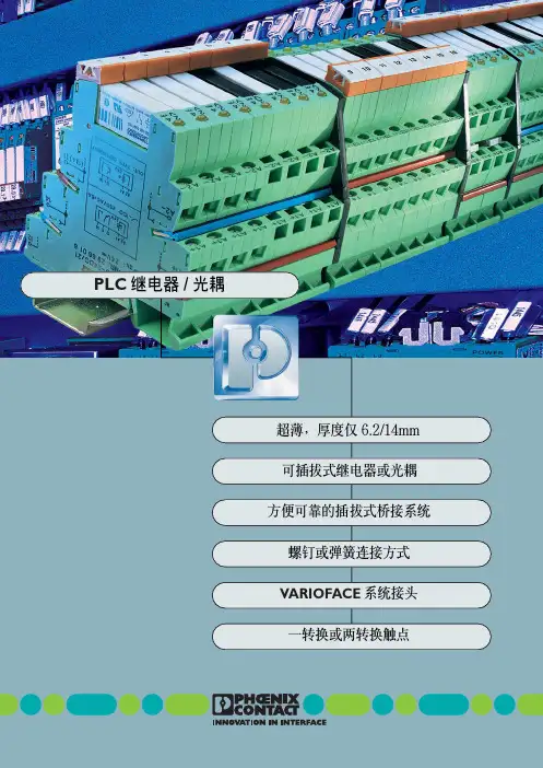


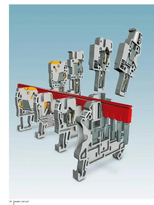
14PHOENIX CONTACT产品一览系统特性1615PHOENIX CONTACT菲尼克斯电气提供独创的CLIPLINE complete组合式端子系列,用户可以根据实际需要任意选择连接方式。
可供选择的连接方式如下:–UT螺钉连接–PT直插式连接–ST回拉式弹簧连接–QT快速免剥线连接–COMBI插拔式连接解决方案–RT螺栓连接无论是螺钉、弹簧、直插、快速免剥线还是螺栓连接,都使用相同的桥接系统,相互之间可以任意桥接。
CLIPLINE complete组合式接线端子具有极大的灵活性。
完全统一的桥接、标识和测试系统能够帮助客户降低选型、配货及物流成本。
CLIPLINE complete组合式接线端子通过了全球的各种标准认证,并且通过了ATEX体系的防爆认证。
该系列可用于防爆区域。
CLIPLINE complete系统特性CLIPLINE complete不同的连接技术,同一套附件系统16PHOENIX CONTACTCLIPLINE complete系统特性CLIPLINE complete更多信息和完整的技术资料,请访问/products灵活的插入式桥接系统全部连接技术都采用统一的插入式桥接系统。
CLIPLINE complete系统所有的接线端子都具有双通道桥接井,可快速、高效地实现多电位分配或转接。
所有接线端子的桥接通道都在同一条直线上,可实现多种桥接方式。
使用2位到50位的插拔式桥接件,可在极短时间内完成全部电位桥接任务。
使用转换桥接件可完成诸如从UT 螺钉端子到ST 回拉式弹簧接线端子之间的转接。
插拔式开关桥可牢靠卡接到桥接井上。
相邻接线端子之间形成可拆式连接。
可插拔连接技术COMBI 可插拔接线端子帮助用户快速实现应用模块化。
和组合接线端子一样,COMBI 插头也可采用螺钉连接(UT)、回拉式弹簧连接(ST)、直插式连接(PT)和快速免剥线连接(QT)技术。
41A 和1000V 最大的额定工作电流和电压满足绝大多数电源和信号回路的接线要求。

德国菲尼克斯电气集团专为电力、通讯、交通、铁路运输、石油化工及工业自动化等行业提供世界一流产品和优良服务,是世界顶尖级电连接专业厂家。
目前在海外32个国家设有子公司,56个国家设有销售处和代表处。
1993年底,德国菲尼克斯电气集团与南京电力自动化研究院(NARI南瑞集团)合资组建了南京菲尼克斯电气有限公司,主要生产并经营菲尼克斯集团各种高质量的电连接件、电子模块、信号变送器、现场总线、防雷浪涌电压保护系统等产品。
南京菲尼克斯电气公司的成立不仅进一步巩固了菲尼克斯产品在电连接行业的领先地位,同时也为中国引进了更多具有世界先进水平的工业自动化产品,有力地促进了国内电气连接及工业自动化技术的发展。
公司自1993年组建以来,仅用三年时间,市场占有率即跃居全国电气接口行业首位。
截止2001年,南京菲尼克斯的业务量已达2亿元,先后在全国各地设立了12个代表处,拥有60多家分销商和经销商。
南京菲尼克斯的迅速崛起,在社会各界引起了较大的反响。
1997年以来公司连续几年被评为江苏省重点外商投资企业、江苏省“AAA”级资信企业、南京市高利税企业、江苏省及南京市外商投资先进企业、南京市三资企业管理工作先进单位、国家级高新技术产业开发区“作出突出贡献企业”。
1999年公司顺利通过ISO9002质量体系认证;2002年公司又顺利通过ISO2000质量体系认证。
德国菲尼克斯集团总部非常看好中国市场,从1996年起多次追加投资,引进各种现代化生产设备,并在南京江宁开发区征地120亩,着手建立其海外最大的生产管理基地——一个具备研发中心的菲尼克斯工业园,为中国用户提供更优质的产品,更完善的服务。
到目前为止,总投资近三千万美元的一家合资公司、两家独资公司已在华成立,中国公司已成为面向中国及亚太地区颇具规模的海外生产基地。
位于南京江宁开发区的公司总部目录PHOENIX CONTACT34Phoenix Contact双出线接线端子UK...-TWIN见20页双出线接地端子UK...-TWIN-PE见22页双进双出接线端子UDK...见24页双进双出接地端子UDK...-PE见25页同向通用接线端子UK...-RETURN见26页同向通用接地端子UK...-RETURN-PE见27页PE/N 输入端子块UK...-PE/N见28页紧凑型的PE/N 输入端子块UIK...-PE/N见29页大电流PE/N 输入端子块UKH...-PE/N见30页桥接件应用表格见32页微型双层接线端子MBKKB 2.5见38页双层通用型接线端子系列UKK...系列见39页通用型接线端子UK...系列见10页大电流接线端子UKH...系列见14页通用型接地端子USLKG...系列见16页大电流接地端子USLKG...系列见19页通用端子建筑安装接线端子UIK (54)N线滑块分断端子UKN...见56页三层建筑安装接线端子PIK (60)分断旋臂式保险丝端子UK...HESI见68页螺帽式保险丝端子UK10-DREHSI见69页刀闸分断端子UK...-MTK见72页双层刀闸分断端子UKK...-MTK见74页可插入元器件插头的基座端子UK...TG见76页元器件插头ST-BE见78页带滑块端子UGSK/S见82页通用试验端子URTK/S (83)微型接线端子MT1.5见90页双层接地端子UKK...-PE见43页传感器接线端子DIK (44)执行器接线端子DOK (46)四层传感器和执行器端子VIOK (48)Phoenix Contact56Phoenix Contact小型带状接线端子MBK 6/E见95页小型带状接地端子MSLKG6见97页螺栓接线端子OTTA...见100页滑块分断螺栓端子OTTA6-T见101页测试插座PSBJ...见122页快速标记条/扁平式快速标记板ZB.../ZBFM...见104页端子组的标识UBE见108页分组标记KLM-A,KLM,KLM 1,KLM 2见109页导线标记套筒PMH...见110页导线标记系统PAB...见111页导线标记牌LM、LS见112页塑料电缆标识夹KMK见114页双层微型接线端子MTTB 1.5见91页小型接线端子MBK...见94页小型接地端子MBK...-PE见96页微型接地端子MT 1.5...-PE见92页Phoenix Contact7剥线工具QUICK-WIREFOX...见129页压线钳CRIMPFOXUD 6...见130页气动式压线钳ZAP...见131页管状预绝缘裸端子A...,AI...,AI-TWIN...,AI-XL...见133页螺丝刀SZ...见130页导轨切割机PPS...见132页安装导轨NS...见116页快速终端固定件/终端固定件/小型终端固定件UHV...、E/....、E/M...见118页绝缘保护罩AP...见115页切线钳CUTFOX..见126页8Phoenix Contact菲尼克斯组合端子的附件组合端子的使用舒适性在很大程度上取决于端子的附件。
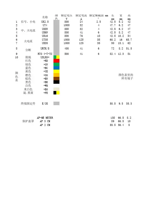
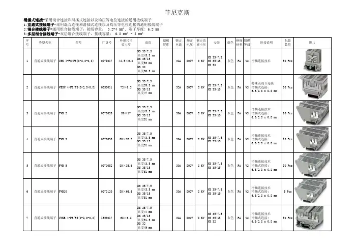
名称额定电压 V额定电流 A额定横截面 mm²长 mm 宽 mm 高 mm1信号、小电流UK2.580024 2.542.5 5.2422UT4100032447.7 6.2473UK5N 80032442.5 6.2474UK6N 80041642.58.2475UK16800761042.510.2546UT3510001253560.21665.77UK351000125355015.1628URTK/S 400416728.251.59RTO 4-T-TC 50041682.412.35110接地USLKG+红色 +RD 绿色 +GN 蓝色 +BU 黄色 +YE 橙色 +OG 棕色 +BN 黑色 +BK 白色 +WH 米白色 +BG 混.黑黄+FE终端固定件E/UK 50.59.535.3AP-ME METER 13866.58.2AP 3 CM 8966.510AP 2 CM 55.556.45分断大电流保护盖罩中、大电流颜色颜色表颜色表里的端子所有端子不一定有颜色表里端板隔板桥接件 螺桥接件 插标识条D-UK2.5ATP-UK FBRI 10-5N EBL 10-5ZB5 LGS1-9D-UT 2,5/10ATP-UK FBS 10-6ZB6 LGS1-10D-UK4/10ATP-UK FBI 10-6EB 10-6ZB6 LGS1-10D-UK4/10ATP-UK FBI 10-8EB 10-8ZB6 LGS1-10D-UK16ATP-UK FBI 10-10EB 10-10ZB10 LGS1-10TPNS-UK FBS 2-16ZB16 LGS1-10KT-S FBI 3-15D-URTK ATS-RTK FB 10-RTK/SSB 4-RTK/SEB 10-8ZB8 LGS1-10D-RT4-TTPNS-UKFBS 10-6ZB8 LGS1-10KLM-A终端固定架中间支撑架APH-ME APT-ME AP 3-TNS 35AP 3-TU AP 2-TU KS AP 2-TU附件:的端子颜色越不常用货期越长。
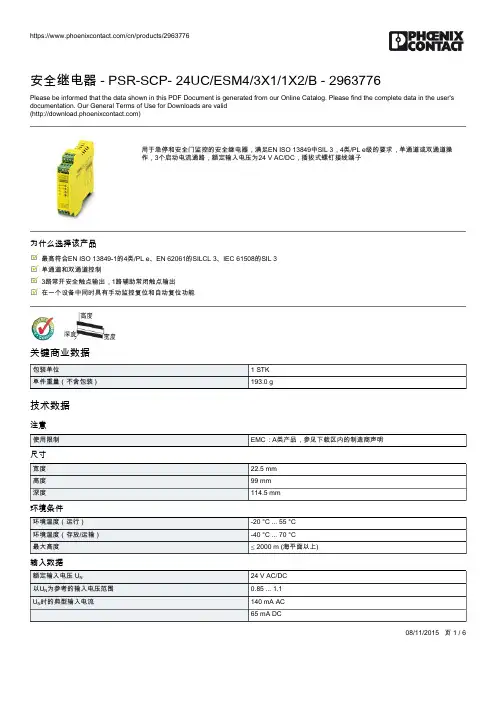
08/11/2015 页 1 / 6安全继电器 - PSR-SCP- 24UC/ESM4/3X1/1X2/B - 2963776Please be informed that the data shown in this PDF Document is generated from our Online Catalog. Please find the complete data in the user's documentation. Our General Terms of Use for Downloads are valid ()用于急停和安全门监控的安全继电器,满足EN ISO 13849中SIL 3,4类/PL e级的要求,单通道或双通道操作,3个启动电流通路,额定输入电压为24 V AC/DC,插拔式螺钉接线端子为什么选择该产品最高符合EN ISO 13849-1的4类/PL e、EN 62061的SILCL 3、IEC 61508的SIL 3 单通道和双通道控制3路常开安全触点输出,1路辅助常闭触点输出 在一个设备中同时具有手动监控复位和自动复位功能关键商业数据技术数据注意尺寸环境条件输入数据安全继电器 - PSR-SCP- 24UC/ESM4/3X1/1X2/B - 2963776技术数据输入数据输出数据常规08/11/2015 页 2 / 6安全继电器 - PSR-SCP- 24UC/ESM4/3X1/1X2/B - 2963776技术数据常规接线数据分类eCl@ssETIMUNSPSC08/11/2015 页 3 / 6安全继电器 - PSR-SCP- 24UC/ESM4/3X1/1X2/B - 2963776分类UNSPSC认证认证认证UL Listed / cUL Listed / Functional Safety / UL Listed / cUL Listed / EAC / Functional Safety / EAC / cULus Listed防爆认证认证已提交认证详情UL ListedcUL ListedFunctional SafetyUL ListedcUL ListedEACFunctional Safety08/11/2015 页 4 / 608/11/2015 页 5 / 6安全继电器 - PSR-SCP- 24UC/ESM4/3X1/1X2/B - 2963776认证EACcULus Listed产品图电路图电路图K3K4MM (N)(L1)L+双通道急停监视08/11/2015 页 6 / 6安全继电器 - PSR-SCP- 24UC/ESM4/3X1/1X2/B - 2963776电路图K3K4M单通道急停监控Phoenix Contact 2015 © - all rights reserved 。


菲尼克斯继电器工作原理菲尼克斯继电器是一种常用的电子元件,它在电路控制和保护方面起着重要作用。
所以了解菲尼克斯继电器工作原理对于电子工程师和电气工程师来说是非常重要的。
本文将详细介绍菲尼克斯继电器的结构、工作原理和应用。
一、菲尼克斯继电器的结构菲尼克斯继电器由三个主要部分组成:电磁系统、动作系统和触点系统。
1.电磁系统:电磁系统是菲尼克斯继电器的核心部分,它由线圈和铁芯组成。
当线圈中通入电流时,产生的磁场会吸引铁芯,使其移动。
2.动作系统:动作系统由铁芯、连接杆、杆簧和挡板组成。
当电磁系统吸引铁芯移动时,连接杆也会跟着移动,通过挡板的作用,将动作力传递给触点系统。
3.触点系统:触点系统由静触点和动触点组成。
当动作系统中的连接杆传递动作力到触点系统时,动触点和静触点之间的接触状态会发生改变。
触点系统可以分为常开触点和常闭触点,分别用于不同的电路控制需求。
二、菲尼克斯继电器的工作原理菲尼克斯继电器基于电磁感应原理工作。
当线圈中通入电流时,产生的磁场会吸引铁芯,使其移动。
这样,通过动作系统将电磁能量转换成机械能量。
动作系统中的连接杆会随着铁芯的移动而移动,进而改变触点系统中动触点和静触点之间的接触状态。
菲尼克斯继电器有两种工作方式:电磁吸合和电磁释放。
1.电磁吸合:当线圈通入电流时,电磁系统产生的磁场会吸引铁芯,使其与连接杆一起向下移动。
连接杆的移动会改变触点系统中动触点和静触点之间的接触状态。
例如,当连接杆移动到动触点与静触点接触时,就会闭合电路,完成电路的通断控制。
这是菲尼克斯继电器的一个常见工作状态。
2.电磁释放:当线圈中的电流停止时,电磁系统没有产生磁场,铁芯没有吸引力,因此连接杆会回到初始位置。
当连接杆回到初始位置时,动触点和静触点之间的接触状态会再次改变,例如,动触点和静触点之间的接触断开,电路闭合的状态也随之解除。
三、菲尼克斯继电器的应用菲尼克斯继电器广泛应用于电力系统、自动化控制系统和汽车电子等领域。
1DescriptionElectronic monitoring relay for voltage monitoring of direct and alternating voltages in single-phase networks EMD-FL-V-300© PHOENIX CONTACT - 09/2009Data sheet INTERFACE Increasingly higher demands are being placed on safety andsystem availability – across all sectors. Processes arebecoming more and more complex, not only in mechanical engineering and the chemical industry, but also in plant and automation technology. Demands on power engineering are also increasing constantly.Error-free and therefore cost-effective operation can only be achieved through continuous monitoring of important network and system parameters. Electronic monitoring relays in the EMD series are available for a wide range of monitoring tasks to avoid the consequences of errors or to keep them within limits.The operating states are indicated using colored LEDs, errors that may occur can be sent to a control system via a floating contact or can shut down a part of the system. Some device versions are equipped with startup and response delays in order to briefly tolerate measured values outside the set monitoring range.–Surge voltage/undervoltage monitoring –Window function–Adjustable threshold values –Adjustable starting override –Adjustable response delay –Error memory–Wide-range power supply unit –Two PDTs102058_en_04FeaturesDescription TypeOrder No.Pcs. / Pkt.Electronic monitoring relay for voltage monitoring of direct and alternating voltages in single-phase networksEMD-FL-V-30028660481Input dataInput name Measuring input Measured value DC, AC sine Protection max. 20 AInput voltage range0 V ... 30 V AC/DC (connection terminal blocks: U1 and GND)0 V ... 60 V AC/DC (connection terminal blocks: U2 and GND)0 V ... 300 V AC/DC (connection terminal blocks: U3 and GND)Maximum input voltage100 V rms (connection terminal blocks: U1 and GND)150 V rms (connection terminal blocks: U2 and GND)440 V rms (connection terminal blocks: U3 and GND)Input resistance of voltage input47 k Ω (connection terminal blocks: U1 and GND)100 k Ω (connection terminal blocks: U2 and GND)470 k Ω (connection terminal blocks: U3 and GND)Maximum temperature coefficient < 0.1 %/K Setting range for response delay 0.1 s ... 10 s Setting range for starting delay 0 s ... 10 sMin. setting range 5 % ... 95 % (From U N )Max. setting range 10 % ... 100 % (From U N )Function Undervoltage, overvoltage, window Basic accuracy ± 5 % (of scale end value)Setting accuracy ≤ 5 % (of scale end value)Repeat accuracy ≤ 2 %Recovery time500 msOutput dataContact type2 floating PDT contactsNominal insulation voltage250 V AC (in acc. with IEC 60664-1)Interrupting rating (ohmic load) max.750 VA (3 A/250 V AC, module aligned, ≤ 5 mm spacing)1250 VA (5 A/250 V AC, module not aligned, ≥ 5 mm spacing)Output fuse5 A (fast-blow)SupplyRange of supply voltages 24 V AC ... 240 V AC -15% ... +10%24 V DC ... 240 V DC -20% ... +25%Frequency range48 Hz ... 400 Hz Nominal power consumption4.5 VA (1.5 W)General dataMains type1-phaseService life mechanical Approx. 2 x 10⁷ cyclesService life, electrical 2 x 10⁵ cycles at ohmic load, 1000 VA Switching frequency max. 60 (per minute at 100 VA ohmic load)max. 6 (per minute at 1000 VA ohmic load)Operating mode 100% operating factorDegree of protectionIP40 (housing) / IP20 (connection terminal blocks)2Ordering data3Technical dataGeneral dataPollution degree 2 (according to EN 50178)Surge voltage category III, basic insulation (as per EN 50178) Rated insulation voltage300 V (According to EN 50178) Assembly on TS 35 profile rail acc. to EN 60715 Mounting position AnyWidth22.5 mmHeight113 mmLength90 mmType of housing Polyamide PA, self-extinguishingColor greenWeight160 gConnection dataConductor cross section, solid0.5 mm² ... 2.5 mm²Conductor cross section, stranded0.25 mm² ... 2.5 mm²Stripping length8 mmType of connection Screw connectionTightening torque 1 NmAmbient conditionsAmbient temperature (operation)-25 °C ... 55 °C-25 °C ... 40 °C (corresponds to UL 508) Ambient temperature (storage/transport)-25 °C ... 70 °CPermissible humidity (operation)15 % ... 85 %Climatic class3K3 (in acc. with EN 60721) Conformance / approvalsConformity CE compliantUL, USA / Canada UL/C-UL listed UL 508 Conformance with EMC directive 2004/108/ECImmunity to interference according to EN 61000-6-2Emitted interference according to EN 61000-6-4Conformance with LV directive 2006/95/ECElectronic equipm. for electrical power installations according to EN 501784Block diagram5Safety notes6Structure1"U" LED: Supply voltage2"MAX" LED: Upper threshold value 3"MIN" LED: Lower threshold value 4"REL" LED: Output relay5"FUNCTION" rotary switch: Function selection 6"DELAY" potentiometer: Response delay 7"MIN" potentiometer: Lower threshold value 8"MAX" potentiometer: Upper threshold value 9"START" potentiometer: Starting override 10Universal snap-on foot for EN DIN rails7InstallationThe module can be snapped onto all 35 mm DIN rails according to EN 60715.An integrated wide-range power supply unit enables the connection of a supply voltage in the range from 24V AC/DC to 240V AC/DC.8DiagnosticsThe LEDs indicate the following error states:"U" LED (Green)–LED ON: Supply voltage present"MIN" and "MAX" LEDs (Red)–LED flashes: Set threshold value exceeded, set delay time is running–LED ON: Set threshold value exceeded, delay time has elapsed–Both LEDs flash alternately: Lower set threshold value is greater than upper threshold value "REL" LED (Yellow)–LED ON: Output relay has picked up–LED OFF: Output relay has dropped out9Connection examples30 V measuring range (U1)60 V measuring range (U2)10300 V measuring range (U3)11FunctionWhen supply voltage U is applied, output relay "R" picks up (yellow "REL" LED is ON) and the starting override (START) starts (green "U" LED flashes). During the starting override, modifications to the measured value have no influence on the position of the output relay. Once the starting override has elapsed, the green "U" LED lights up permanently. For all functions the "MIN" and "MAX" LEDs flash alternately if the minimum value selected is greater than the maximum value.The "FUNCTION" rotary switch is used to set the desired function:–O = Surge voltage monitoring (OVER)–U = Undervoltage monitoring (UNDER)–W = Monitoring of the area between thresholds MIN andMAX (window function) (WIN)–WL = Monitoring of the area between thresholds MIN andMAX (window function) with error memory (WIN + LATCH)–UL = Undervoltage monitoring with error memory(UNDER + LATCH)–OL = Surge voltage monitoring with error memory(OVER + LATCH)Surge Voltage Monitoring (OVER and OVER + LATCH) If the measured voltage exceeds the value set at the "MAX" controller, the set response delay (DELAY) starts (red "MAX" LED flashes). After the delay time has elapsed (red "MAX" LED is ON), output relay "R" drops out (yellow "REL" LED is OFF). If the measured voltage falls below the value set at the "MIN" controller (red "MAX" LED is OFF), output relay "R" picks up again (yellow "REL" LED is ON).If the error memory has been activated (OVER + LATCH) and the measured voltage has exceeded the value set at the "MAX" controller for longer than the set response delay, output relay "R" does not pick up if the voltage falls below the value set at the "MIN" controller.Once the error has been reset (supply voltage interrupted), output relay "R" picks up when the supply voltage is applied again and the measuring cycle starts again once the set starting override (START) has elapsed.Undervoltage Monitoring (UNDER and UNDER + LATCH) If the measured voltage falls below the value set at the "MIN" controller, the set response delay (DELAY) starts (red "MIN" LED flashes). After the delay time has elapsed (red "MIN" LED is ON), output relay "R" drops out (yellow "REL" LED is OFF). If the measured voltage exceeds the value set at the "MAX" controller, output relay "R" picks up again (yellow "REL" LED is ON).If the error memory has been activated (UNDER + LATCH) and the measured voltage has fallen below the value set at the "MIN" controller for longer than the set response delay, output relay "R" does not pick up if the voltage exceeds the value set at the "MAX" controller.Once the error has been reset (supply voltage interrupted), output relay "R" picks up when the supply voltage is applied again and the measuring cycle starts again once the set starting override (START) has elapsed.Window Function (WIN and WIN + LATCH)Output relay "R" picks up (yellow "REL" LED is ON) if the measured voltage exceeds the value set at the "MIN" controller. If the measured voltage exceeds the value set at the "MAX" controller, the set response delay (DELAY) starts (red "MAX" LED flashes). After the delay time has elapsed (red "MAX" LED is ON), output relay "R" drops out (yellow "REL" LED is OFF).Output relay "R" picks up again (yellow "REL" LED is ON) if the measured voltage falls below the maximum value again (red "MAX" LED is OFF). If the measured voltage falls below the value set at the "MIN" controller, the set response delay (DELAY) starts (red "MIN" LED flashes). After the delay time has elapsed (red "MIN" LED is ON), output relay "R" drops out (yellow "REL" LED is OFF).If the error memory has been activated (WIN + LATCH) and the measured voltage has fallen below the value set at the "MIN" controller for longer than the set response delay, output relay "R" does not pick up if the minimum value is exceeded. If the measured voltage has exceeded the value set at the "MAX" controller for longer than the set response delay, output relay "R" likewise does not pick up when the voltage falls below the maximum value.Once the error has been reset (supply voltage interrupted), output relay "R" picks up when the supply voltage is applied again and the measuring cycle starts again once the set starting override (START) has elapsed.。
菲尼克斯EMD-FL-3V-400三相电压监视继电器菲尼克斯EMD-FL-3V-400三相电压监视继电器功能:监视3 相电压,带可调限值、延时,还可监视相序和缺相,以及对称性。
功能的设置在面板的最后一个旋钮:-UNDER 欠压监视-UNDER+SEQ 欠压和相序监视-WIN 欠压和过压监视-WIN+SEQ 欠压和过压监视,同时有相序监视菲尼克斯EMD-FL-3V-400三相电压监视继电器结构:1, LED:非对称性ASYM 2, LED:最大值 3, LED:最小值4, LED:相序SEQ 5, LED:输出继电器REL6,电位计ASYM 非对称性 7,电位计MAX8,电位计MIN 9,电位计DELAY 反应时间10,功能设置旋钮 11,卡脚TOP1功能描述:1,欠压监视UNDER,或欠电压监视+相序监视UNDER+SEQ:设置步骤:1)将面板的功能设置旋钮打至“U”,如带相序监视则打至“US”;2)设置电位计MIN:例:如当电压低于320V 时报警,则按照计算公式:(报警下限-额定电压)/额定电压=(320-400)/400=-20%所以电位计MIN 设为-20%。
当测量电压小于下限时的持续时间超过设置的延时时间,则继电器触点动作(即15 和18断开,25 和28 断开)。
3)设置电位计MAX:在欠压监视模式下,MAX 代表的是一个磁滞区,用于避免振荡。
如虽然当电压低于320V时要报警,此时继电器会切换,但如果此时测量电压在320V(MIN)附近振荡时,继电器输出会频繁动作,所以通过设置一个MAX 值,可以使电压大于该值时继电器才恢复。
电位计MAX 就是设置这个磁滞的。
如只有当测量电压大于360V 时,才不做欠压报警。
按照公式:(360-400)/400=-10%,所以电位计MAX 设为-1 0%。
需要注意的是,当测量电压高于MAX,则继电器触点立刻恢复(即15 和16 断开,25和26 断开),延时时间不起作用。
名称额定电压 V额定电流 A额定横截面 mm²长 mm 宽 mm 高 mm1信号、小电流UK2.580024 2.542.5 5.2422UT4100032447.7 6.2473UK5N 80032442.5 6.2474UK6N 80041642.58.2475UK16800761042.510.2546UT3510001253560.21665.77UK351000125355015.1628URTK/S 400416728.251.59RTO 4-T-TC 50041682.412.35110接地USLKG+红色 +RD 绿色 +GN 蓝色 +BU 黄色 +YE 橙色 +OG 棕色 +BN 黑色 +BK 白色 +WH 米白色 +BG 混.黑黄+FE终端固定件E/UK 50.59.535.3AP-ME METER 13866.58.2AP 3 CM 8966.510AP 2 CM 55.556.45颜色表颜色表里的端子所有端子不一定有颜色表里分断大电流保护盖罩中、大电流颜色端板隔板桥接件 螺桥接件 插标识条D-UK2.5ATP-UK FBRI 10-5N EBL 10-5ZB5 LGS1-9D-UT 2,5/10ATP-UK FBS 10-6ZB6 LGS1-10D-UK4/10ATP-UK FBI 10-6EB 10-6ZB6 LGS1-10D-UK4/10ATP-UK FBI 10-8EB 10-8ZB6 LGS1-10D-UK16ATP-UK FBI 10-10EB 10-10ZB10 LGS1-10TPNS-UK FBS 2-16ZB16 LGS1-10KT-S FBI 3-15D-URTK ATS-RTK FB 10-RTK/SSB 4-RTK/SEB 10-8ZB8 LGS1-10D-RT4-TTPNS-UKFBS 10-6ZB8 LGS1-10KLM-A终端固定架中间支撑架APH-ME APT-ME AP 3-TNS 35AP 3-TU AP 2-TU KS AP 2-TU的端子颜色越不常用货期越长。