固态换向接触器CONTACTRON 4合1菲尼克斯接插件
- 格式:pdf
- 大小:342.13 KB
- 文档页数:16
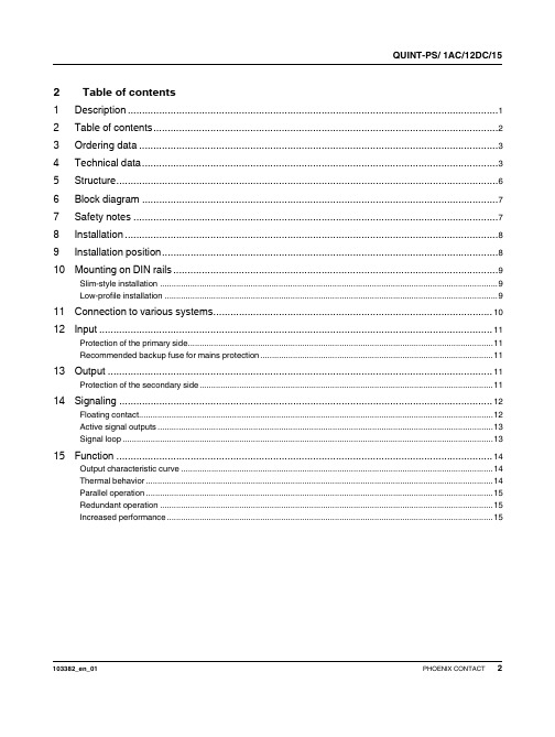
1DescriptionPrimary-switched power supply with SFB technology, 1 AC, output current 15 AQUINT-PS/ 1AC/12DC/15© PHOENIX CONTACT - 03/2009Data sheet INTERFACE QUINT POWER power supply units – highest system availability due to SFB technologyCompact power supply units of the new QUINT POWER generation maximize the availability of your system. Even the standard power circuit-breakers can be tripped reliably and quickly with the SFB technology (Selective Fusebreaking Technology) and six times the nominal current for 12 ms. Defective current paths are disconnected selectively, the defect is limited and the important system parts remain in operation. A comprehensive diagnostics is carried out by continuously monitoring the output voltage and current. This preventive function monitoring visualizes the criticaloperating modes and reports them to the control unit before an error occurs.–Quick tripping of standard power circuit breakers with dynamic SFB technology power reserve–Reliable starting of difficult loads with static POWER BOOST power reserve–Preventive function monitoring –Can be used worldwide–High degree of operational safety due to high MTBF > 500 000 h, long mains buffering times > 20 ms, high dielectric strength up to 300 V AC103382_en_01Features2Table of contents1Description (1)2Table of contents (2)3Ordering data (3)4Technical data (3)5Structure (6)6Block diagram (7)7Safety notes (7)8Installation (8)9Installation position (8)10Mounting on DIN rails (9)Slim-style installation (9)Low-profile installation (9)11Connection to various systems (10)12Input (11)Protection of the primary side (11)Recommended backup fuse for mains protection (11)13Output (11)Protection of the secondary side (11)14Signaling (12)Floating contact (12)Active signal outputs (13)Signal loop (13)15Function (14)Output characteristic curve (14)Thermal behavior (14)Parallel operation (15)Redundant operation (15)Increased performance (15)Description TypeOrder No.Pcs. / Pkt.Primary-switched power supply with SFB technology, 1 AC, output current 15 AQUINT-PS/ 1AC/12DC/1528667181AccessoriesTypeOrder No.Pcs. / Pkt.Assembly adapter for QUINT POWER 10A on S7-300 rail QUINT-PS-ADAPTERS7/229382061Universal wall adapterUWA 182/5229382351Input dataInput nominal voltage range 100 V AC ... 240 V AC AC input voltage range 85 V AC ... 264 V AC Short-term input voltage 300 V ACDC input voltage range 90 V DC ... 350 V DC AC frequency range 45 Hz ... 65 Hz DC frequency range 0 HzCurrent consumption Approx. 1.9 A (120 V AC)Approx. 0.9 A (230 V AC)Inrush current limitation < 15 A (typical)I 2t< 1.5 A 2sPower failure bypass > 65 ms (120 V AC)> 65 ms (230 V AC)Typical response time < 0.5 sProtective circuitry Transient surge protection Varistor Input fuse, integrated6.3 A (slow-blow, internal)Recommended backup fuse for mains protection 10 A16 A (characteristic B)Discharge current to PE< 3.5 mAOutput dataNominal output voltage12 V DC ±1%Setting range of the output voltage 5 V DC ... 18 V DC (> 12 V constant capacity)Output current15 A (-25°C ... 70°C)16 A (with POWER BOOST, -25°C ... 40°C permanent)60 A (with SFB technology, 12 ms)Derating From +60°C 2.5% per KelvinControl deviation< 1 % (change in load, static 10% ... 90%)< 2 % (change in load, dynamic 10% ... 90%)< 0.1 % (change in input voltage ±10%)Power loss nominal load max.21 W Maximum power dissipation idling 5 WEfficiency > 89 % (for 230 V AC and nominal values)Ascent time < 0.5 msResidual ripple< 10 mV PP (with nominal values)Peak switching voltages 40 mV PPConnection in parallel Yes, for redundancy and increased capacity Connection in seriesYesSurge protection against internal surge voltages Yes, limited to approx. 25 V DC Resistance to reverse feedMax. 25 V DC3Ordering data4Technical dataDC OK activeOutput description U OUT > 0.9 x U N: High signalVoltage+ 5 V DC ... 12 V DCCurrent≤ 20 mA (short circuit resistant)Status display"DC OK" LED green / U OUT < 0.9 x U N: LED flashing DC OK floatingOutput description Relay contact, U OUT > 0.9 x U N: Contact closed Voltage≤ 30 V AC/DC (≤ 0.5 A / at 60 V AC/DC)Current≤ 1 AStatus display"DC OK" LED green / U OUT < 0.9 x U N: LED flashing POWER BOOST, activeOutput description I OUT < I N: High signalVoltage+ 5 V DC ... 12 V DCCurrent≤ 20 mA (short circuit resistant)Status display LED "BOOST", yellow / I OUT > I N: LED onGeneral dataInsulation voltage input/output 4 kV AC (type test)2 kV AC (routine test)Insulation voltage input / PE 3.5 kV AC (type test)2 kV AC (routine test)Insulation voltage output / PE500 V DC (routine test)Degree of protection IP20Class of protection I, with PE connectionMTBF> 500 000 h in acc. with IEC 61709 (SN 29500) Housing material Steel sheet, zinc-platedDimensions W / H / D (state of delivery)60 mm / 130 mm / 125 mmDimensions W / H / D (90° turned)122 mm / 130 mm / 63 mmWeight 1.1 kgAmbient conditionsAmbient temperature (operation)-25 °C ... 70 °C (> 60°C derating)Ambient temperature (storage/transport)-40 °C ... 85 °CMax. permissible relative humidity (operation)95 % (at 25°C, no condensation)Vibration (operation)< 15 Hz, amplitude ±2.5 mm in acc. with IEC 60068-2-615 Hz ... 150 Hz, 2.3g, 90 min.Shock30g in all directions in acc. with IEC 60068-2-27 Pollution degree in acc. with EN 501782Climatic class3K3 (in acc. with EN 60721)StandardsElectrical Equipment for Machinery EN 60204Safety transformers for power supply units IEC 61558-2-17Electrical safety (of information technology equipment)IEC 60950/VDE 0805 (SELV)Electronic equipment for use in electrical power installations EN 50178/VDE 0160 (PELV)SELV IEC 60950 (SELV) and EN 60204 (PELV)Safe isolation DIN VDE 0100-410DIN VDE 0106-1010Protection against electric shock DIN 57100-410Protection against electric shock, basic requirements for safe isolation inDIN VDE 0106-101electrical equipmentStandards (Continued)Limitation of mains harmonic currents EN 61000-3-2Device safety GS (tested safety)Network variants (undervoltage)Semi F47-200Certificate CB SchemeApprovalsUL approvals UL Listed UL 508UL/C-UL Recognized UL 60950Conformance with EMC guideline 2004/108/EC and for low-voltage guideline 2006/95/ECNoise immunity according to EN 61000-6-2Electrostatic discharge EN 61000-4-2Housing Level 4Contact discharge8 kVDischarge in air15 kVComments Criterion BElectromagnetic HF field EN 61000-4-3Housing Level 4Frequency range80 MHz ... 1000 MHzField intensity20 V/mComments Criterion AFast transients (burst)EN 61000-4-4Input 4 kV (level 4 - asymmetrical)Output 2 kV (level 1 - asymmetrical)Signal 1 kV (level 1 - asymmetrical)Comments Criterion BSurge current loads (surge)EN 61000-4-5Input 4 kV (inst. class 4 - asymmetrical: conductor to ground)2 kV (inst. class 4 -symmetrical: conductor to conductor)Output 2 kV (level 3 - asymmetrical: conductor to ground)1 kV (level 1 - symmetrical: conductor to conductor)Signal 1 kV (level 3 - asymmetrical: conductor to ground)Comments Criterion BConducted interference EN 61000-4-6Input/Output/Signal Level 3 - asymmetricalFrequency range0.15 MHz ... 80 MHzVoltage10 VComments Criterion AVoltage dips EN 61000-4-11Input(mains buffering > 20 ms)Comments Criterion BEmitted interference in acc. with EN 61000-6-3Radio interference voltage in acc. with EN 55011EN 55011 (EN 55022) Class B, area of application: Industry and residential Emitted radio interference in acc. with EN 55011EN 55011 (EN 55022) Class B, area of application: Industry and residential5Structure1AC input2DC output3POWER BOOST switching output, active4DC OK switching output active5DC OK output, floating6Potentiometer 5 V DC ... 18 V DC7"DC OK" LED8"BOOST" LED9Universal DIN rail adapter UTA 107/30[mm2]AWG[Nm]solid stranded TorqueInput0.2-2.50.2-2.516-120.5-0.6Output0.2-2.50.2-2.516-120.5-0.6Signal0.2-2.50.2-2.516-120.5-0.6Input dataInput nominal voltage range100 V AC ... 240 V ACAC input voltage range85 V AC ... 264 V ACShort-term input voltage300 V ACDC input voltage range90 V DC ... 350 V DCAC frequency range45 Hz ... 65 HzDC frequency range0 HzInput fuse, integrated 6.3 A (slow-blow, internal)Recommended backup fuse for mains protection10 A16 A (characteristic B)Type of connection Pluggable screw connectionStripping length7 mmOutput dataNominal output voltage12 V DC ±1%Setting range of the output voltage 5 V DC ... 18 V DC (> 12 V constant capacity)Output current15 A (-25°C ... 70°C)16 A (with POWER BOOST, -25°C ... 40°C permanent)60 A (with SFB technology, 12 ms)Type of connection Pluggable screw connectionStripping length7 mm6Block diagram7Safety notes8InstallationThe power supply unit can be snapped onto allDIN rails in acc. with EN 60715. They must bemounted horizontally (connecting terminalblocks top and bottom).9Installation positionSlim-style installation: Installation depth 125 mm (+ DIN rail)(state at delivery)Low-profile installation: Installation depth 63 mm (+ DIN rail)10Mounting on DIN railsSlim-style installationAssembly:Position the module with the DIN rail guide on the upper edgeof the DIN rail, and snap it in with a downward motion.Removing:Pull the snap lever open with the aid of a screwdriver and slidethe module out at the lower edge of the DIN rail.Low-profile installationLow-profile installation can be achieved by mounting the device at right-angles to the DIN rail. Mount the DIN rail adapter (UTA 107/30) as described in the figure. No additional mounting material is required. Fixing screws: Torx T10 (torque 0.8 Nm ... 0.9 Nm).11Connection to various systemsThe connection for 100V AC ... 240 V AC is established using the L, N, and P screw connections.The device can be connected to 1-phase AC networks or to two of the phase conductors of three-phase systems (TN, TT or IT systems in accordance with VDE 0100-300/IEC 60364-3) with nominal voltages of 100 V AC ... 240 V AC.The device also continues to work on short-term input voltages >300V AC.12InputProtection of the primary sideThe device must be installed in acc. with the regulations as inEN 60950. It must be possible to disconnect the device usinga suitable isolating facility outside the power supply.The primary side line protection, for example, is suitable. Fordevice protection, there is an internal fuse. Additional deviceprotection is not necessary.Recommended backup fuse for mains protectionPower circuit breaker 10 A or 16 A, characteristic B (oridentical function). In DC applications, a suitable fuse must bewired in upstream.13OutputThe connection is established using screw connections onthe screw connection of the DC output:12 V DC: "+" and "–"; DC OK switching output active: "DC OK"and "–"; DC OK output floating: "13" and "14"; POWERBOOST switching output active: "I < I N" and "–".The set output voltage is 12 V DC at the time of delivery. Theoutput voltage can be set on the potentiometer.Protection of the secondary sideThe device is electronically protected against short circuit andidling. In the event of a malfunction, the output voltage islimited to 25 V DC.14SignalingThe active signal output, the floating signal contact and the active POWER BOOST switching output are provided for function monitoring. The DC OK-LED and the BOOST-LED also enable the function evaluation of the power supply unit directly on the operation site (refer to the output characteristic curve).I < I N I > I N U OUT < 0.9 x U N"DC OK" LED ON ON Flashing"BOOST" LED OFF ON ONActive DC OK switchingoutputON ON OFFFloating DC OK output Closed Closed OpenActive POWER BOOSTswitching outputON OFF OFFMeaning Normal operation of thepower supply POWER BOOST operation,e.g. to start loadsOverload mode, e.g.consumer short circuit oroverloadFloating contactThe floating signal contact opens and indicates that the set output voltage has undershot by more than 10%. Signals and ohmic loads of up to maximum 30V and currents of maximum 1A (or maximum 60V with maximum 0.5A) can be switched. For heavily inductive loads such as a relay, a suitable protection circuit (e.g. damping diode) is necessary.Active signal outputsThe 5 ... 12 V DC signal is applied between the "DC OK" and the "–" connection terminal blocks or between "I < I N" and "–" and can carry up to 20 mA. By switching from "active high" to "low", the DC OK signal output signalizes when the output voltage is fallen short of by more than 10%.The DC OK signal is decoupled from the power output. It is thus not possible for devices connected in parallel to act as an external power supply.The 5 ... 12 V DC signal can be directly connected to a logic input for evaluation.The POWER BOOST signal output signalizes that the nominal current is exceeded.Signal loopMonitoring two devices: Use the active signal output of device 1 and loop in the floating signal output of device 2. In the event of malfunctioning, a common alarm is output. Any number of devices can be looped in. This signal combination saves wiring costs and logic inputs.15FunctionOutput characteristic curveThe power supply unit operates with the static POWER BOOST power reserve as per the U/I characteristic curve given in the figure. In case of ambient temperaturesT amb<+40°C,I BOOST is available permanently; it is available only for a few minutes in case of higher temperatures. In the event of a secondary short circuit and overload, the output current is limited to I BOOST. Thereby, the module does not switch off, but supplies a continuous output current. The secondary voltage is reduced until the short circuit has been remedied. The U/I characteristic curve with the POWER BOOST power reserve ensures that high inrush currents of capacitive loads and of consumers with DC/DC converters in the input circuit can be fed reliably.In order to trip the standard power circuit breakers magnetically and thus very quickly, QUINT POWER supplies six times the nominal current for 12ms with the help of the SFB technology. The defective current path is switched off using this dynamic power reserve; consumers connected in parallel continue to operate without an interruption. The error is thus restricted and the important system parts continue to operate.The characteristic curve shows when I<IN, I>I N andU<0.9x U N. The relevant signaling is given in the table.U N = 12 VI N = 15 AI BOOST = 16 ASFB technology = 60 AP N = 180 WP BOOST = 192 WThermal behaviorWith an ambient temperature of up to +40°C, the device supplies the continuous output current of I BOOST. The device can supply a nominal output current of I N with ambient temperatures of up to +60°C. In the case of ambient temperatures above +60°C, the output current must be reduced by 2.5% per Kelvin increase in temperature. The device does not switch off at ambient temperatures of +70°C or thermal overload. The output capacity is reduced as far as necessary to provide device protection. After it has cooled down, the output capacity is increased again.Parallel operationDevices of the same type can be connected in parallel to enable both redundancy and an increase in efficiency. No other alignment is necessary when in the state of delivery.If the output voltage is adjusted, a uniform distribution of power is guaranteed by setting all parallel operated power supply units to exactly the same output voltage.To ensure symmetrical distribution of power, we recommend designing all cable connections from the power supply unit to a busbar of the same length and with the same conductor cross section. The system makes it advisable to install a protective circuit at the output of each device when more than two power supply units are connected in parallel (e.g. decoupling diode or DC fuse). This prevents high reverse feed currents in the event of a secondary device fault.Redundant operationRedundant circuits are suitable for the supply of systems which make especially high requirements on the operational safety. If a fault occurs in the primary circuit of the first power supply unit, the second device automatically takes over the entire power supply, without interruption, and vice versa. For this reason, the power supply units to be connected in parallel are dimensioned in such a way that the total current requirement of all consumers can be completely covered by one power supply unit. 100% redundancy makes external decoupling diodes necessary (QUINT-DIODE/40, Order No. 2938963)!Increased performanceFor n parallel connected devices, the output current can be increased to n x I N. Parallel connection to increase efficiency is used for the expansion of existing systems. It is advisable to use parallel connection if the power supply unit does not cover the current requirement of the most powerful consumer. Otherwise the consumers should be spread among individual devices independent of one another. A maximum of five devices can be connected in parallel!。


电气基础知识接触器科技名词定义中文名称:接触器英文名称:contactor定义:能频繁关合、承载和开断正常电流及规定的过载电流的开断和关合装置。
所属学科:电力(一级学科);配电与用电(二级学科)本内容由全国科学技术名词审定委员会审定公布接触器接触器(Contactor)是指工业电中利用线圈流过电流产生磁场,使触头闭合,以达到控制负载的电器。
接触器由电磁系统(铁心,静铁心,电磁线圈)触头系统(常开触头和常闭触头)和灭弧装置组成。
其原理是当接触器的电磁线圈通电后,会产生很强的磁场,使静铁心产生电磁吸力吸引衔铁,并带动触头动作:常闭触头断开;常开触头闭合,两者是联动的。
当线圈断电时,电磁吸力消失,衔铁在释放弹簧的作用下释放,使触头复原:常闭触头闭合;常开触头断开。
目录分类结构说明接触器与继电器的区别技术发展接触器的触头接触不牢靠的原因及处理方法简介分类结构说明接触器与继电器的区别技术发展接触器的触头接触不牢靠的原因及处理方法展开简介在电工学上,因为可快速切断交流与直流主回路和可频繁地接通与大电流控制(某些型别可达800安培)电路的装置,所以经常运用于电动机做为控制对象﹐也可用作控制工厂设备﹑电热器﹑工作母机和各样电力机组等电力负载,接触器不仅能接通和切断电路,而且还具有低电压释放保护作用。
接触器控制容量大,适用于频繁操作和远距离控制。
是自动控制系统中的重要元件之一。
在工业电气中,接触器的型号很多,电流在5A-1000A的不等,其用处相当广泛。
海关HS编码:85364100(主电路电压<=60V的接触器),85364900(60V<主电路电压<=1000V的接触器),85353000(主电路电压>1000V的接触器)分类通用接触器可大致分以下两类。
1交流接触器。
主要有电磁机构。
触头系统。
灭弧装置等组成。
常用的是CJ10。
CJ12。
CJ12B等系列。
2直流接触器,一般用于控制直流电器设备,线圈中通以直流电,直流接触器的动作原理和结构基本上与交流接触器是相同的。


德国菲尼克斯电气集团专为电力、通讯、交通、铁路运输、石油化工及工业自动化等行业提供世界一流产品和优良服务,是世界顶尖级电连接专业厂家。
目前在海外32个国家设有子公司,56个国家设有销售处和代表处。
1993年底,德国菲尼克斯电气集团与南京电力自动化研究院(NARI南瑞集团)合资组建了南京菲尼克斯电气有限公司,主要生产并经营菲尼克斯集团各种高质量的电连接件、电子模块、信号变送器、现场总线、防雷浪涌电压保护系统等产品。
南京菲尼克斯电气公司的成立不仅进一步巩固了菲尼克斯产品在电连接行业的领先地位,同时也为中国引进了更多具有世界先进水平的工业自动化产品,有力地促进了国内电气连接及工业自动化技术的发展。
公司自1993年组建以来,仅用三年时间,市场占有率即跃居全国电气接口行业首位。
截止2001年,南京菲尼克斯的业务量已达2亿元,先后在全国各地设立了12个代表处,拥有60多家分销商和经销商。
南京菲尼克斯的迅速崛起,在社会各界引起了较大的反响。
1997年以来公司连续几年被评为江苏省重点外商投资企业、江苏省“AAA”级资信企业、南京市高利税企业、江苏省及南京市外商投资先进企业、南京市三资企业管理工作先进单位、国家级高新技术产业开发区“作出突出贡献企业”。
1999年公司顺利通过ISO9002质量体系认证;2002年公司又顺利通过ISO2000质量体系认证。
德国菲尼克斯集团总部非常看好中国市场,从1996年起多次追加投资,引进各种现代化生产设备,并在南京江宁开发区征地120亩,着手建立其海外最大的生产管理基地——一个具备研发中心的菲尼克斯工业园,为中国用户提供更优质的产品,更完善的服务。
到目前为止,总投资近三千万美元的一家合资公司、两家独资公司已在华成立,中国公司已成为面向中国及亚太地区颇具规模的海外生产基地。
位于南京江宁开发区的公司总部目录PHOENIX CONTACT3。
The switch actuator REG-K/12x230/16 with manual mode (referred to below as the actuator ) can switch twelve loads via separate, floating make contacts.Y ou can also manually switch the connected loads with manual switches on the actuator without bus voltage.The actuator has a bus coupler. It is installed on a DIN rail, with the bus connection made via a bus connecting terminal. It is supplied with power from the bus voltage. A data rail is not required.For your safetyHAZARD OF ELECTRIC SHOCK, EXPLOSION, OR ARC FLASHSafe electrical installation must be carried out only by skilled professionals. Skilled professionals must prove profound knowledge in the following areas:•Connecting to installation networks •Connecting several electrical devices •Laying electric cables•Connecting and establishing KNX networks •Safety standards, local wiring rules and regulations Failure to follow these instructions will result in death or serious injury.RISK OF FATAL INJURY FROM ELECTRIC SHOCK The output may carry electrical current even when the load is switched off.•When working on the device: Always disconnect the device from the supply by means of the fuse in the in-coming circuit.•Even if the manual switch is in the …OFF“ position, aKNX telegram can switch the connections to being live at any time. Before working on the device, always diconnect the fuse in the incoming circuit from the supply.Failure to follow these instructions will result in death or serious injury.Getting to know the switch actuatorA Bus connecting terminal, max. 4 core pairsB Programming LED (red LED)C Programming buttonD Cable coverE Operating LED (green LED)F Manual switchG Screw terminals1Set the actuator onto the DIN rail.2Connect KNX.¼WARNINGRisk of fatal injury from electrical current. The device could become damaged.Safety clearance must be guaranteed inaccordance with IEC 60664-1. There must be at least 4 mm between the individual cores of the 230 V supply cable and the KNX line.Connections, displays and operatingelementsMounting the actuatorRISK OF FATAL INJURY FROM ELECTRIC SHOCKVoltage may be present at the outputs when the mains voltage is connected to the system.If subjected to strong vibrations during transportation, the switch contacts might change to the enabled state.After connecting the bus voltage, set the relays of the channels to the position desired simply by switching …On/Off“ or by changing the manual switch to …OFF“.Failure to follow these instructions will result indeath or serious injury.3Connect the bus voltage.4Switch the relays of the channels on and offmanually once with the manual switches.5Connect the load.The cables to the loads as well as the system voltages (L1, L2 or L3) are connected via screw terminals for max. 16 A. Every two L connections are bridged internally.6Connect the mains voltage.Now you can check the functionality of the actuator and the connected loads without having to load the application from the ETS. (See the "Operating the actuator" section.)1Press the programming button.The programming LED lights up.2Load the physical address and application into thedevice from the ETS.The programming LED goes out.The operating LED lights up: The application was loaded successfully, the device is ready for operation.Putting the actuator into operationSpaceLogic KNXSwitch actuator REG-K/12x230/16 with manual modeOperating instructionsArt. no. MTN648493Normally, you control connected devices using push-buttons or by remote control. However, you canmanually switch each of the actuator's channels on and off directly at the manual switches.Schneider Electric Industries SAS 35 rue Joseph Monier Rueil Malmaison 92500 FranceIf you have technical questions, please contact the Cus-tomer Care Centre in your /contactOperating the actuatorT echnical dataExternal auxiliary voltage:NonePower supply from bus:DC 24V/max. 10mA Insulation voltage:AC 4 kV between bus and 230V ACSwitch contacts:12 x make contacts, floating Nominal voltage:AC 230V , 50 to 60Hz Nominal current:16A, cos ϕ = 0.6Connected loadIncandescent lamps:AC 230V , max. 3600W with 10,000 switching cyclesHalogen lamps:AC 230 V , max. 2500 W with 10,000 switching cycles Fluorescent lamps:AC 230V , max. 2500VA, parallel-compensated,with 5,000 switching cycles Capacitive load:AC 230V , 16A max. 200μF with 5,000 switching cycles Minimum loads:≥ 24V DC, 100mASwitching frequency:max. 10 per minute at nominal loadAmbient temperature Operation:-5°C to +45°C Storage:-25°C to +55°C Transport:-25°C to +70°CEnvironment:The device is designed for use at a height of up to 2000m above sea level (MSL).Max. humidity:93%, no moisture condensationOperating elements:Programming button,twelve manual switches for manual operationDisplay elements:Red LED for programming check,green LED to indicate device availabilityConnections Bus:via two 1 mm pins for bus connecting terminal Outer conductor:eleven 3-gang screwterminals (1–11) and one 2-gang screw terminal (12) for each max. 2.5mm 2Installation width:12depth units = approx. 216mmEC guidelines:Corresponds to Low-Voltage guideline 73/23/EEC and EMC guideline 89/336/EECSchneider Electric -ContactSchneider Electric Limited Telford, TF3 3 BL, UKUK RepresentativeStafford Park 5V 6484-562-02 11/21。
1DescriptionPoE injectorINJ 1...© PHOENIX CONTACT Data sheetThe injectors connect Ethernet devices without PoE(e.g. switches) with PoE-ready end devices (e.g. IP cameras). The injector as power sourcing equipment (PSE) provides the required power to a powered device (PD) by way of the data cable.The injector and end device negotiate the electrical power requirements autonomously. Ensure that end devices with an electrical power requirement of up to 30 W fulfill the requirements of IEEE 802.3af and at.Features–Compliant with IEEE 802.3 af (PoE) and IEEE 802.3 at (PoE+) up to 30 W–Product versions up to60 W for 4-pair PoE (PoE++)–Automatic detection of IEEE 802.3at or 802.3af PD–DIP switch for selecting the cable pairs for the transfer of energy in mode A or B–Extended supply voltage range of 18 V DC ... 57 V DC, redundant–10/100/1000 Mbps–Extended temperature range of -40 °C ...+75 °C–Safe shield connection to ground potential–Mounting on a DIN railMake sure you always use the latest documentation.It can be downloaded from the product at /products.This document is valid for the products listed in 3 …Ordering data“ . 107973_en_012018-11-192Table of contents1Description (1)2Table of contents (2)3Ordering data (3)4Technical data (6)5Safety regulations and installation notes (8)5.1 UL notes (8)6Product description (9)6.1 Accessories: power supply (9)6.2 Dimensions (10)6.3 Function elements (10)6.4 Setting the DIP switches (11)7Installation (12)7.1 Mounting (12)7.2 Removal (12)7.3 RJ45 interface (12)7.4 Power Supply Voltage (12)Description T ype Order No.Pcs./Pkt. PoE injector, 30 W, two RJ45 sockets,10/100/1000 Mbps, DIN rail mounting, IP20INJ 100027030051PoE injector, 30 W, two RJ45 sockets,10/100/1000 Mbps, DIN rail mounting, IP20,expanded temperature range of -40°C ... 75°CINJ 1000-T27030061PoE injector, 60 W, two RJ45 sockets,10/100/1000 Mbps, DIN rail mounting, IP20INJ 101027030071PoE injector, 60 W, two RJ45 sockets,10/100/1000 Mbps, DIN rail mounting, IP20, expanded temperature range of -40°C ... 75°C INJ 1010-T270300813Ordering dataAccessories T ype Order No.Pcs./Pkt. Patch panel, two RJ45 sockets, 10/100/1000 Mbps,DIN rail mounting, IP20PP-RJ-RJ27030151Patch panel, RJ45 socket on screw terminal blocks,10/100/1000 Mbps, DIN rail mounting, IP20,shield contacting with strain reliefPP-RJ-SC27030161Patch panel, RJ45 socket on Push-in terminal blocks,10/100/1000 Mbps, DIN rail mounting, IP20,shield contacting with strain reliefPP-RJ-SCC27030181Patch panel, RJ45 socket on IDC terminal blocks,10/100/1000 Mbps, DIN rail mounting, IP20,shield contacting with strain reliefPP-RJ-IDC27030191Patch panel, two RJ45 sockets, 10/100/1000 Mbps,DIN rail mounting, IP20, shield current monitoring,surge protectionPP-RJ-RJ-F27030201Patch panel, RJ45 socket on screw terminal blocks,10/100/1000 Mbps, DIN rail mounting, IP20,shield contacting with strain relief,shield current monitoring, surge protectionPP-RJ-SC-F27030211Patch panel, RJ45 socket on Push-in terminal blocks,10/100/1000 Mbps, DIN rail mounting, IP20,shield contacting with strain relief,shield current monitoring, surge protectionPP-RJ-SCC-F27030221Patch panel, RJ45 socket on IDC terminal blocks,10/100/1000 Mbps, DIN rail mounting, IP20,shield contacting with strain relief,shield current monitoring, surge protectionPP-RJ-IDC-F27030231Crimping pliers, for assembling the RJ45 plugs FL PLUGRJ45..., for assembly on siteFL CRIMPTOOL27448691Accessories T ype Order No.Pcs./Pkt.FL CAT5 HEAVY27448141CAT5-SF/UTP cable (J-02YS(ST)C HP 2 x 2 x 24 AWG),heavy-duty installation cable, 2 x 2 x 0.22 mm², solidconductor, shielded, outer sheath: 7.8 mm diameter, innersheath: 5.75 mm ±0.15 mm diameter cable, EthernetCAT5 (100 Mbps), 4-position, Halogen-free compound,HM 2 in acc. with VDE 0207, water blue RAL 5021, cablelength: Free input (0.25 ... 1000.0 m)CAT5-SF/UTP cable (J-02YS(ST)C HP 2 x 2 x 24 AWG),FL CAT5 HEAVY CONF/27448271heavy-duty installation cable, 2 x 2 x 0.22 mm², solidconductor, shielded, outer sheath: 7.8 mm diameter, innersheath: 5.75 mm ±0.15 mm diameter, preassembled onboth sides with RJ45 plug, crossover or line networkcable, number of positions: 4, 100 Mbps, CAT5FL CAT5 FLEX27448301CAT5-SF/UTP cable (J-LI02YS(ST)C H 2 x 2 x 26 AWG),light-duty, flexible installation cable 2 x 2 x 0.14 mm²,stranded, shielded, outer sheath: 5.75 mm ±0.15 mmdiameterCAT5-SF/UTP cable (J-LI02YS(ST)C H 2 x 2 x 26 AWG),FL CAT5 FLEX CONF/27448431light-duty, flexible installation cable 2 x 2 x 0.14 mm²,stranded, shielded, outer sheath: 5.75 mm ±0.15 mmdiameter, preassembled on both sides with RJ45 plug,crossover or line assignment network cable, number ofpositions: 4, 100 Mbps, CAT5FL ISOLATOR 100-RJ/SC23139281 Passive network isolator for electrical isolation in Ethernetnetworks. This protects Ethernet devices from potentialdifferences of up to 4 kV. Can be used for transmissionspeeds of up to 100 Mbps. Connection using RJ45 andCOMBICON plug-in screw terminal block.Passive network isolator for electrical isolation in EthernetFL ISOLATOR 100-RJ/RJ23139311 networks. This protects Ethernet devices from potentialdifferences of up to 4 kV. Can be used for transmissionspeeds of up to 100 Mbps. Possible to connect two RJ45plugs.FL ISOLATOR 1000-RJ/RJ23139151 Passive network isolator for electrical isolation in Ethernetnetworks. This protects Ethernet devices from potentialdifferences of up to 4 kV. Can be used for transmissionspeeds of up to 1 Gbps. Possible to connect two RJ45plugs.FL ISOLATOR 100-M1229029851 Passive network isolator for electrical isolation in Ethernetnetworks. For the protection of Ethernet devices againstpotential differences of up to 4 kV. Can be used fortransmission speeds of up to 100 Mbps. Ethernetconnection via two M12 sockets (D-coded).Patch cable, CAT5, assembled, 0.3 m FL CAT5 PATCH 0,3283225010Patch cable, CAT5, assembled, 0.5 m FL CAT5 PATCH 0,5283226310Patch cable, CAT5, assembled, 1 m FL CAT5 PATCH 1,028*******Patch cable, CAT5, assembled, 1.5 m FL CAT5 PATCH 1,5283222110Patch cable, CAT5, assembled, 2 m FL CAT5 PATCH 2,028*******Patch cable, CAT5, assembled, 3 m FL CAT5 PATCH 3,028*******Patch cable, CAT6, pre-assembled, 0.3 m FL CAT6 PATCH 0,3289118110 Patch cable, CAT6, pre-assembled, 0.5 m FL CAT6 PATCH 0,5289128810 Patch cable, CAT6, pre-assembled, 1.0 m FL CAT6 PATCH 1,028******* Patch cable, CAT6, pre-assembled, 1.5 m FL CAT6 PATCH 1,5289148210 Patch cable, CAT6, pre-assembled, 2.0 m FL CAT6 PATCH 2,028******* Patch cable, CAT6, pre-assembled, 3.0 m FL CAT6 PATCH 3,028******* Patch cable, CAT6, pre-assembled, 5.0 m FL CAT6 PATCH 5,028******* Patch cable, CAT6, pre-assembled, 7.5 m FL CAT6 PATCH 7,5289188010 Patch cable, CAT6, pre-assembled, 10 m FL CAT6 PATCH 10289187710 Patch cable, CAT6, pre-assembled, 12.5 m FL CAT6 PATCH 12,528913695 Patch cable, CAT6, pre-assembled, 15.0 m FL CAT6 PATCH 15,028913725 Patch cable, CAT6, pre-assembled, 20.0 m FL CAT6 PATCH 20,028915765 Stripping tool, for the multi-level stripping of shieldedcablesVS-CABLE-STRIP-VARIO16574071RJ45 connector, degree of protection: IP20, number ofpositions: 8, 1 Gbps, CAT5 (IEC 11801:2002), material:PA, connection method: IDC fast connection, connectioncross section: AWG 26- 23, cable outlet: straight, color:traffic grey A RAL 7042VS-08-RJ45-5-Q/IP2016567251RJ45 connector, degree of protection: IP20, number ofpositions: 8, 1 Gbps, CAT5 (IEC 11801:2002), material:PA, connection method: IDC fast connection, connectioncross section: AWG 26- 23, cable outlet: straight, color:blackVS-08-RJ45-5-Q/IP20 BK16580081Actuation tool, for ST terminal blocks, also suitable for useas a bladed screwdriver, size: 0.4 x 2.5 x 75 mm,2-component grip, with non-slip gripSZF 0-0,4X2,5120450410Electronic diagonal cutter, tapered head, angled (21°),without chamfer, with opening springMICROFOX-SP12124881Network cable, Ethernet CAT6A (10 Gbps), 8-position,PUR halogen-free, water blue RAL 5021, shielded, freecable end, on free cable end, cable length: Free entry(0.5 ... 400 m)VS-OE-OE-94F/ (14173591)Primary-switched UNO POWER power supply for DIN railmounting, input: 1-phase, output: 24 V DC/60 WUNO-PS/1AC/24DC/ 60W29029921Primary-switched TRIO POWER power supply with push-in connection for DIN rail mounting, input: 1-phase, output: 24 V DC/3 A C2LPS TRIO-PS-2G/1AC/24DC/3/C2LPS29031471Primary-switched power supply unit, QUINT POWER, Push-in technology, DIN rail mounting, input: 1-phase, output: 24 V DC / 2.5 A QUINT4-PS/1AC/24DC/2.5/PT29095761Please observe section 6.1 …Accessories: power supply“ when selecting the power supply. Accessories T ype Order No.Pcs./Pkt.4Technical dataSupply INJ 1000INJ 1000-T INJ 1010 INJ 1010-TSupply voltage range18 V DC ... 57 V DC(Ordinary locations)24 V DC ... 48 V DC(Hazardous locations)18 V DC ... 57 V DC (Ordinary locations) 24 V DC ... 48 V DC (Hazardous locations)Nominal supply voltage24 V DC48 V DC 24 V DC 48 V DCMax. current consumption 2.1 A 4.2 AMaximum current consumption (Ex areas) 1.4 A (24 V DC)0.7 A (48 V DC)2.73 A (24 V DC) 1.34 A (48 V DC)Power consumption≤ 75 W≤ 75 WProtective circuit Reverse polarity protection Reverse polarity protection Conductor cross section, flexible0.75 mm² ... 4.00 mm²0.75 mm² ... 4.00 mm²Conductor cross section, solid0.75 mm² ... 4.00 mm²0.75 mm² ... 4.00 mm²Conductor cross section AWG20 AWG ... 12 AWG20 AWG ... 12 AWGEthernet INJ 1000INJ 1000-T INJ 1010 INJ 1010-TConnection method RJ45 CAT5e RJ45 CAT5eOutput power30 W60 WOutput nominal voltage54 V DC (PoE)54 V DC (PoE)Serial transmission speed10/100/1000 Mbps10/100/1000 Mbps Transmission length100 m (including patch cables)100 m (including patch cables)Connection line twisted pair, shielded, CAT5 orbetter twisted pair, shielded, CAT5 or betterPin assignment1:11:1General dataBasic functions PSE/Midspan, compliant with IEEE 802.3af, atDegree of protection IP20 (Non-certificated by UL)Mounting position verticalMounting type DIN rail mountingDimensions (W/H/D)30.2 mm x 130 mm x 120 mmExternal cable diameter 5.5 mm ... 6.5 mmHousing material Plastic grayVibration resistance in acc. with EN 60068-2-6/IEC 60068-2-610 Hz ... 57 Hz, amplitude ±3.5 mm, 57 Hz ... 150 Hz, 5g Shock in acc. with EN 60068-2-27/IEC 60068-2-2725g for 11 ms, three shocks in each direction Electromagnetic compatibility Conformance with EMC Directive 2014/30/EUAmbient conditions INJ 1000INJ 1010INJ 1000-T INJ 1010-TAmbient temperature (operation)0 °C ... 60 °C-40 °C ... 75 °C Ambient temperature (storage/transport)-40 °C ... 85 °C-40 °C ... 85 °CPermissible humidity (operation)10 % ... 95 %(non-condensing)10 % ... 95 % (non-condensing)Altitude5000 m (for restrictions seemanufacturer's declaration)2000 m (with UL approval)5000 m (for restrictions see manufacturer's declaration) 2000 m (with UL approval)Approvals / CertificatesConformance CE-compliantUL, USA/Canada Class I, Div. 2, Groups A, B, C, D, T4Noxious gas test ISA-S71.04-1985 G3 Harsh Group AConformance with EMC Directive 2014/30/EUNoise immunity according to EN 61000-6-2Electrostatic discharge EN 61000-4-2Contact discharge± 6 kV (Test Level 3)Discharge in air± 8 kV (Test Level 3)Indirect discharge± 6 kVComments Criterion BElectromagnetic HF field EN 61000-4-3Frequency range80 MHz ... 3 GHz (Test Level 3)Field intensity10 V/mComments Criterion AFast transients (burst)EN 61000-4-4Input± 2.2 kV (1 minute)Signal± 2.2 kV (1 minute)Comments Criterion BSurge current loads (surge)EN 61000-4-5Input± 0.5 kVSignal± 1 kV (Data line, asymmetrical)± 2 kV (I/O cable on field side only, asymmetric)Comments Criterion BConducted interference EN 61000-4-6Frequency range0.15 MHz ... 80 MHzVoltage10 VComments Criterion AEmitted interference in acc. with EN 61000-6-4Interference emission EN 61000-6-4, Class A, industrial applicationsEN 61000-6-3, Class B, domain of use: residential and small commercial5Safety regulations and installation notes•Installation, operation, and maintenance may only be carried out by qualified electricians. Follow theinstallation instructions as described.•When installing and operating the device, the applicable regulations and safety directives (including national safety directives), as well as general technical regulations, must be observed. The technical data isprovided in this package slip and on the certificates(conformity assessment, additional approvals whereapplicable).•The device must not be opened or modified. Do not repair the device yourself, replace it with an equivalent device. Repairs may only be carried out by themanufacturer. The manufacturer is not liable fordamage resulting from violation.•If the equipment is used in a manner not specified by the manufacturer, the protection provided by the equipment may be impaired.•The IP20 protection (IEC 60529/EN 60529) of the device is intended for use in a clean and dryenvironment. The device must not be subject tomechanical strain and/or thermal loads, which exceed the limits described (non-certificated by UL).•This device may be powered with a SELV/PELV power supply unit. A SELV power supply provides additional protection in the event of an Ethernet cable failure.5.1UL notes•Do not block the device's ventilation holes.•Suitable for indoor use only.•Altitude up to 2000 m•The equipment shall only be used in an area of not more than pollution degree 2, as defined in IEC/EN 60664-1.•Use qualified power supply by SELV or double insulation of UL 60950 or UL 61010-1 or UL 61010-2-201 standards.•The devices are open-type and are required to be installed in an enclosure suitable for the environmentand that can only be accessed with the use of a tool.•The equipment is suitable for use in Class I, Division 2, Groups A, B, C, and D or non-hazardous locations only.6Product description6.1Accessories: power supplyINJ 1000, INJ 1000-TINJ 1010, INJ 1010-TProduct variantsOrder No.DesignationPower Port 2T emperature rangeFunction2703005INJ 100030 WRJ45 socket 0 °C ... 60 °C2703006INJ 1000-T-40 °C ... 75 °C 2703007INJ 101060 W0 °C ... 60 °C 2703008INJ 1010-T -40 °C ... 75 °CThe following product versions are described in a separate data sheet:2703009INJ 1100-T 30 WRJ45 socket -40 °C ... 75 °C Electrical isolation2703010INJ 1110-T 60 WThe following product versions with advanced functions are described in a separate data sheet:2703011INJ 2101-T 30 W Screw terminalblocks-40 °C ... 75 °C Potential separation, surge protection andshield current monitoring2703012INJ 2102-T IDC terminal blocks1004065INJ 2103-TPush-in terminal blocks2703013INJ 2111-T 60 W Screw terminalblocks2703014INJ 2112-T IDC terminal blocks 1004066INJ 2113-T Push-in terminalblocks PoE output 0 W ... 30 W2902992UNO-PS/1AC/24DC/ 60W2903147TRIO-PS-2G/1AC/24DC/3/C2LPS 2909576QUINT4-PS/1AC/24DC/2.5/PT PoE output 0 W ... 30 W2902992UNO-PS/1AC/24DC/ 60W2903147TRIO-PS-2G/1AC/24DC/3/C2LPS 2909576QUINT4-PS/1AC/24DC/2.5/PT PoE output 31 W ... 60 W2902994UNO-PS/1AC/24DC/90W/C2LPS 2903148TRIO-PS-2G/1AC/24DC/52909577QUINT4-PS/1AC/24DC/3.8/PT6.2DimensionsFigure 1Dimensions6.3Function elementsFigure 2Function elements1US1GND Supply voltage US2GND Redundant supply voltage 2RJ45 socket Data 3DIP switch 4RJ45 socket Data + PoE 5LED No function 6LED S2Status Mode B 4, 5, 7, 8 On Power supply PD OKFlashing Overload mode B, short circuit,startup failed, cable under load isolatedOFF PD not supplied or no PD connected 7LED S1Status Mode A 1, 2, 3, 6 On Power supply PD OK Flashing Overload mode A, short circuit,startup failedS1 + S2 flashingInternal error, PoE chip too hot8LED U2Supply voltage US29LED U1Supply voltage US1107973_en_01PHOENIX CONTACT 11 / 126.4Setting the DIP switchesINJ 1000, INJ 1000-TBy default upon delivery, PoE is modulated on data cables 1, 2, 3,6.The cables 4, 5, 7, 8 are not used at a transmission with 100 Mbps (spare pairs). If you set DIP 1 to ON, PoE is modulated on these spare pairs.•Use DIP 1 to select over which two wire pairs the PoEfeed is to be transmitted.•Restart the device to adopt these settings.INJ 1010, INJ 1010-TGuideline IEEE 802.3bt for end devices with an electrical power requirement greater than 30 W has not yet been published. For this reason, the injector and end device may not be able to negotiate the electrical power requirements autonomously in rare cases.This can occur in particular when the PSE and PD chips are from different manufacturers.•Check the cabling.•If the devices do not automatically mediate the powerrequirement, switch DIP 1 to ON.•Restart the device to adopt these settings.•If this is not successful, switch DIP 2 to ON also. DIP 1no longer has a function.•Restart the device to adopt these settings.Contact Phoenix Contact when thesemeasures do not help.Keep the documentation of your end device ready.107973_en_0112 / 12PHOENIX CONTACT GmbH & Co. KG • 32823 Blomberg • Germany7Installation7.1MountingFigure 3Mounting on a DIN railThe device is intended for installation in a control cabinet.•Connect a 35 mm EN DIN rail to the protective earth viaa grounding terminal block. The device is grounded by snapping it onto the DIN rail.•Snap the device onto the DIN rail.7.2RemovalFigure 4Removal•Push down the locking tab with a screwdriver, needle-nose pliers or similar.•Slightly pull the bottom edge of the device away from the mounting surface.•Pull the device away from the DIN rail.7.3RJ45 interface•Only twisted pair cables with an impedance of 100 Ω can be connected to the RJ45 Ethernet interface.•Insert the Ethernet cable with the RJ45 plug into the TP interface until the plug engages audibly. Observe the plug keying.7.4Power Supply Voltage•Connect the supply voltage to US1 and GND.•Optionally, you can connect a redundant supply voltage to US2 and GND.。