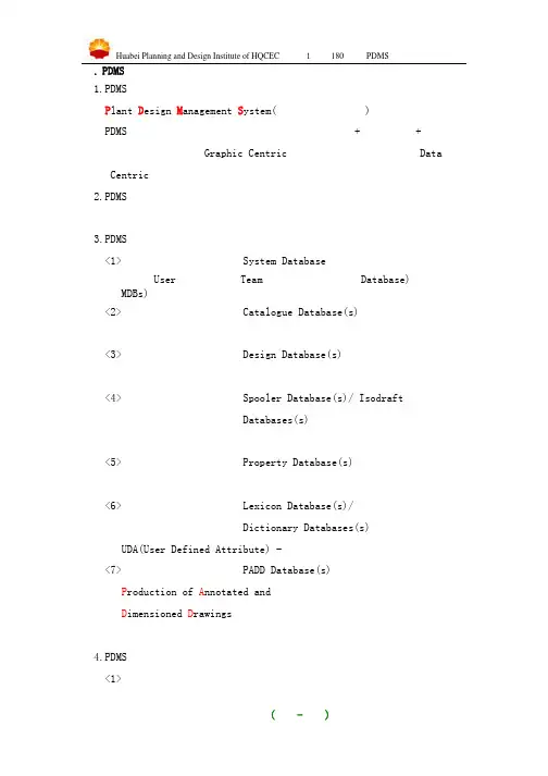
SW6使用方法-寰球
- 格式:pdf
- 大小:637.68 KB
- 文档页数:18
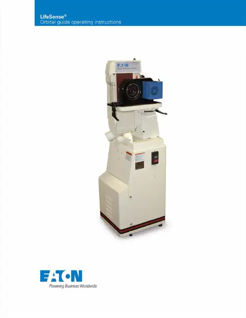
EATON LifeSense orbital guide operating instructions E-HOAS-CC001-E October 20152Table of contentsContentsGeneral information 3Safety instructions 3Electrical requirements 3Installation / environment 4Maintenance 4LifeSense hose clean up / preparation 4LifeSense isolation test 6Notes 7Contact information 81234563Image shown Eaton Part Number ET0100-005124563Orbital Guide Start / Stop SwitchOrbital GuideOrbital Guide Locking HandlesDebris ShroudVent* * S hop vacuums with spark arresters are required.Vertical Sander Start / Stop ButtonGeneral informationThe LifeSense orbital guide (ET0100-001) was designed with the specific intent to aid in, and expedite, the mandatory hose end cleanup process when producing a LifeSense hose assembly. The orbital guide was designed by Eaton and is a required piece of equipment in making a LifeSense hose assembly.The purpose of this manual is to present the basic operating, maintenance, and safety information for the Eaton LifeSense orbital guide and a JET J-4300A vertical belt sander (Eaton part number ET0100-005).Safety instructions -general safety precautionsRead and understand this manual beforeattempting to operate the equipment.Failure to follow operating instructions may lead todeath, severe injury, or property damage.PREVENT UNAUTHORIZED OPERATION:DO NOT permit anyone to operate this machine unlessthey have read and thoroughly understood this manual.WEAR SAFETY GLASSES:Risk of eye injury! Eye protection is required at alltimes during the installation, operation and maintenance of this machine. FAILURE TO FOLLOW THIS WARNING MAY LEAD TO DEATH, SEVERE INJURY, ORPROPERTY DAMAGE.KEEP WORK AREA CLEAN:Cluttered areas and benches invite accidents.W EAR SAFETY GLOVES:Safety gloves should be worn at all times during the operation of the orbital guide. FAILURE TO FOLLOW THIS WARNING MAY LEAD TO DEATH, SEVERE INJURY,OR PROPERTY DAMAGE.Only the hose mandrels specifically designed for use with the orbital guide should be inserted into the orbital guide. FAILURE TO FOLLOW THIS WARNING MAY LEAD TO DEATH, SEVERE INJURY, OR PROPERTY DAMAGE.EMERGENCY STOPS:To turn off the orbital guide push the toggle switch on top of the motor shroud. (See Figure 1). To turn the vertical belt sander off at any time, push the red E-Stopbutton located on the front of the machine.This deactivates the sander. (See Figure 2).Figure 1Figure 2Electrical requirementsThe orbital guide is supplied with an electrical enclosure and toggle on/off switch which requires a 120-volt, 15-amp power source. The JET J-4300A vertical belt sander also requires 120-volt, 20-amp service.EATON LifeSense orbital guide operating instructions E-HOAS-CC001-E October 20153EATON LifeSense orbital guide operating instructions E-HOAS-CC001-E October 20154Installation / environmentOnly qualified personnel should be utilized for installation of the unit. FAILURE TO FOLLOW THIS WARNING MAY LEAD TO DEATH, SEVERE INJURY , OR PROPERTY DAMAGE.When installing the orbital guide onto a vertical belt sander, align the guide bar on the bottom of the orbital guide with the guide bar slot on the sander table/platen. This will ensure the orbital guide is parallel with the sander belt. Finally, ensure that the bottom back ledge of the orbital guide overlaps the sander table next to the belt, while at the same staying with in the sander manufacturer's recommended min./max. distance from the belt. This will prevent debris from building up on the sander table top. Install a vent system with a spark arrester at the belt sander outlet.The JET J-4300A vertical belt sander, or any belt sander, must be installed indoors on a level surface, in a clean, dry environment and in a manner that meets consumer safety standards.MaintenanceKeep rubber debris from accumulating at the back of the orbital guide between the sanding belt and clear safety screen by removing it regularly. Excessive rubber debris accumulation from the sanding process can cause belt damage, begin to smoke, or catch fire. FAILURE TO FOLLOW THIS WARNING MAY LEAD TO DEATH, SEVERE INJURY , OR PROPERTY DAMAGE.As the belt wears down, the orbital guide will need to be shuttled to another section of the belt. Simply loosen the two black locking handles, slide the fixture, and re-tighten.(See Figure 3). Replacement belts should be 100 grit.Figure 3LifeSense hose end clean up Prepping or cleaning the end of a cut LifeSense hose is a mandatory step in the LifeSense hose assembly process. Utilize Eaton’s orbital guide (ET0100-001), mounted to a vertical belt sander and the proper mandrel for the given hose size. This clean-up step isolates the first and second deck of the wire reinforcement; avoiding continuity between the two decks.Step 1: Select mandrel Turn the power off on the orbital guide and sander. Then select the correct size mandrel insert for thehose size. (See Figure 4).Figure 4Step 2: Insert mandrel Slide the mandrel into the orbital housing until it bottomsout. (See Figure 5). Figure 5EATON LifeSense orbital guide operating instructions E-HOAS-CC001-E October 20155Step 3: T urn on powerTurn the orbital guide on by moving the toggle on/off switch to the “On” position. If you are using the JET sander, press the green power button to activatethe sander. (See Figures 6 & 7).Figure 6Figure 7Step 4: Hose end clean up Insert the hose into the mandrel until the hose makes contact with the sanding belt. Only light pressure needs to be applied to achieve a good bevel; CAUTION: DO NOT push the hose aggressively against the belt as the belt willwear prematurely or tear. (See Figure 8).Figure 8Hold the hose steady while applying light pressure. Allow the hose to turn 3-5 revolutions. CAUTION: DO NOTallow the hose to turn in your hands. (See Figure 9).Figure 9EATON LifeSense orbital guide operating instructions E-HOAS-CC001-E October 20156Figure 10Step 5: Visually inspectVisually inspect the hose end to ensure no wires are touching between the first and second layers. (See Figure 10).Step 6: Isolation testTo verify separation between hose layers an isolation test must be conducted. Y ou can do so by using the Eaton test gauge (ET0100-002) and plier gauge (ET0100-003) or a multimeter.Using Eaton gaugesIf using the Eaton test gauge, insert the positive and negative wires of the test pliers into the corresponding ports on the test gauge. Then insert the pliers into the hose and squeeze the handles firmly to pierce the inner and outer wire reinforcement layers. While maintaining pressure on the handles press the button on the test gauge. Both lights, hose and connection, should illuminate green. (See Figure 11).If one or both of the lights illuminate red, reposition pliers, apply firm pressure on the handles, and re-test. If a light(s) remain red examine both hose ends to verify the wire decks are truly separated. (See Figures 12 & 10).Using a multimeterIf using a multimeter, turn the multimeter on and locate the Ohm setting (Ω) on the dial. Place the tip of one probe on the outer wire reinforcement and the other on the inner layer. The resistance reading MUST be greater than5,000 ohms. (See Figure 13).Figure 11Figure 12Figure 13NotesEATON LifeSense orbital guide operating instructions E-HOAS-CC001-E October 20157© 2015 EatonAll Rights ReservedPrinted in USADocument No. E-HOAS-CC001-E October 2015Assembly EquipmentTechnical Support | Service | Spare Parts 1-888-AT-LOMAR(1-888-285-6627)(517-563-8800)EatonHydraulics Business USA 14615 Lone Oak Road Eden Prairie, MN 55344 USATel: 952-937-9800Fax: 952-294-7722 /hydraulics EatonHydraulics Business EuropeRoute de la Longeraie 71110 MorgesSwitzerlandTel: +41 (0) 21 811 4600Fax: +41 (0) 21 811 4601EatonHydraulics Group Asia PacificEaton BuildingNo.7 Lane 280 Linhong RoadChangning District,Shanghai 200335ChinaTel: (+86 21) 5200 0099Fax: (+86 21) 2230 7240。
一. PDMS的简介1.PDMS的含义P lant D esign M anagement S ystem(工厂设计管理体系)PDMS是在计算机上创建全比例三维模型软件,几何+属性、图纸+报告,并非“以图形为中心(Graphic Centric)”而是“以数据为中心(DataCentric)”。
2.PDMS的特征单一的数据源、数据库易维护管理、易客户化、成熟的应用功能工具等特征。
3.PDMS数据库的类型<1>系统数据库 System Database用户(User)权限、组(Team),数据库访问模式Database)、数据库组MDBs);<2>元件数据库 Catalogue Database(s)几何形状、连接方式、描述及材料、等级规范;<3>设计数据库 Design Database(s)设备、管道、土建及结构、暖通、电缆桥架、支吊架;<4>管段数据库 Spooler Database(s)/ IsodraftDatabases(s)管件、管段、焊点、连接点;<5>特性数据库 Property Database(s)材料属性、应力分析数据;<6>用户定义属性数据库 Lexicon Database(s)/Dictionary Databases(s)UDA(User Defined Attribute) -用户定义的属性(标准属性之外);<7>二维图数据库 PADD Database(s)P roduction of A nnotated andD imensioned D rawings图形、注释、尺寸。
4.PDMS的功能及模块划分<1>项目管理模块ADMIN (项目管理)DICE (数据完整性检查)RECONFIGURER (数据库重整)LEXICON (定义用户定义属性)<2>应用模块MONITOR (用户权限控制)<3>元件库和等级库模块SPECON (等级表)PARAGON (元件库)PROPCON (特性库)<4>设计模块设备、管道、土建结构、暖通、电缆桥架、支吊架、设计模板<5>设计分析模块CLASHER (碰撞检查)DATAL (数据库列表)REPORTER (数据报表)<6>出图模块DRAFT (图纸生成)ISODRAFT (单管图生成)<7>管段下材料模块SPOOLER (管段资料输入)二. PDMS的简单安装与设置1.安装应用程序Pdms11.5sp1操作系统Window NT/2000/XP 磁盘格式是NTFS2.拷贝中文字库拷贝f1105811901.gfb到Pdms11.5sp1主目录3.安装Pdms11.5Toolkit8.5到Pdms11.5sp1主目录(Toolkits工具集随需要升版安装)安装Toolkit后,PDMS的第一次运行用个人用户名和密码进入Monitor打开命令行Display>Command Line键入Pml rehash all进入Design,Monitor>Modules>Design>Macro files…4.安装Catview11.3到C:\AVEVA\Catview11.3主目录(Catview属于外挂程序,拷贝即可使用)在Catview目录中包含三个文件Evars.bat 环境变量设置文件NAMING.DOC PDMS 元件命名规则PDMS Catview User Guide.pdf 用户指南Catview的设置编辑Catview目录中的Evars.bat,将Catview指到正确的路径上Rem Set path to the main Catview directoryset catview=C:\AVEVA\catview11.3编辑Pdms11.5主目录中的Evars.bat文件,在文件的最后调用Catview目录中的Evars.batCall C:\AVEVA\catview11.3\evars.bat重新进入Paragon,刷新程序索引文件Tools>Pml Debug>Pml rehash All或打开命令行Display>Command Line键入Pml rehash all5.License.bat文件的替换和启动方式此文件是软件厂家控制正版软件的一种手段,机号和文件是一一对应,由软件厂家提供并且不定期替换,但安装和启动均由用户完成。
北京寰球科研中心TOA广播系统培训资料2012年10月20日资料序号:1、现场培训资料2、V X2000系统操作手册和安装手册(电子版)3、广播系统图、机柜图、接线图4、系统软件配置文件(电子版)现场培训资料:一、VX-2000系统介绍:VX-2000系统是一套最大可满足8进50出的音频管理系统,4条母线结构,最大可满足4路音频信号同时输出。
通过话筒进行远程管理,话筒按键可通过系统软件自行定义,包括消防手动报警语音播放(启动和停止);背景音乐模式播放(启动和停止);业务分区呼叫(单区,多区或全区);音量调整(每次为3Db);故障报警显示(话筒、功放、主机、喇叭线路等故障);分区监听等。
二、寰球科研中心背景音乐系统情况:该项目共有5栋楼,分别为A、B、C、D、E共5栋建筑,37个广播分区:其中A座每层为1个广播分区,共8个分区;B 座每层为一个广播分区,共7个分区(不含6层);C 座每层为1个广播分区,共6个分区(不含5层,6层);D座每层为一个广播分区,共8个分区;E座每层为一个广播分区,共8个分区。
三、具体操作步骤:1、播放背景音乐第1步:逐一打开位于机柜后方的电源插排开关,以便给所有设备通电。
通电后,所有设备显示红灯,由于各设备主机检测时间的差异,各设备逐渐会由红灯转换为绿灯状态,待所有设备均显示绿灯后,系统进入待机状态。
第2步:按下位于话筒上背景音乐模式按键,至该键绿灯亮起,表示进入工作状态。
第3步:启动要播放的系统音源,如CD机,待CD机显示读秒后,CD开始播放音乐文件。
第4步:按下位于话筒上背景音乐模式结束按键,至该键绿灯亮起,此时第2步操作取消,背景音乐播放停止。
背景音乐的播放模式:背景音乐的播放模式在系统管理软件中,预先设定完成,一经设定,只能按照该模式进行背景音乐的播放,如需更改模式,需要重新通过软件设定并上传到系统主机完成更改。
2、业务广播:业务广播可通过两种方式完成:1)人工呼叫:第1步:人工手动选取要呼叫的广播区域,可单区,多区或全区,至该区绿灯亮起;第2步:按下呼叫按钮,待话筒钟声响起并完成后,利用话筒向所选区域进行广播;第3步:广播完成后,再次按下呼叫按钮至该灯熄灭,并按下呼叫取消键,完成人工呼叫。
UV WinLab V6 简明使用手册珀金埃尔默仪器(上海)有限公司孙明编译目录第一章总则第二章UV WinLab V6软件的安装第三章登录UV WinLab第四章UV WinLab概述和基本定义第五章在UV WinLab中添加仪器第六章建立方法第七章方法的设置——中档仪器篇第八章方法的设置——高档仪器篇第九章数据处理程序第十章运行与数据显示第十一章报告与模板第1章总则UV WinLab V6 是PerkinElmer公司Lambda系列紫外/可见/近红外分光光度计的操作软件,功能包括对Lambda 25、35、45系列以及早期的Lambda 20、40、40P 、20Bio、40Bio系列,Lambda650、750、850、950系列和Lambda800、900系列仪器的控制,数据的采集、储存和处理等。
UV WinLab V6软件包含了UV WinLab V6和UV WinLab Data Processor & Viewer两个程序,后者是一个独立的数据处理程序,用于对单独的光谱进行数据处理。
UV WinLab V6有两个版本,分别是标准版和ES版本,后者加强了有关安全保护方面的设置以进一步满足21 CFR Part 11的要求。
UV WinLab V6工作在Microsoft Windows XP SP2系统环境下,从UV WinLabV6.03起,兼容Microsoft Windows Vista系统,并在上述环境下通过测试。
UV WinLab V6 ES版本必须采用NTFS分区格式进行安装,PerkinElmer建议标准版也采用NTFS 分区格式进行安装。
与UV WinLab V3及以前版本的操作软件不同,UV WinLab V6是一个全新编写的“工作流程(Work Flow)”模式的软件系统,即软件模拟实际测量工作的过程来进行有关参数的设定,用户按所需要的操作一步一步地进行设置,建立方法,然后执行。
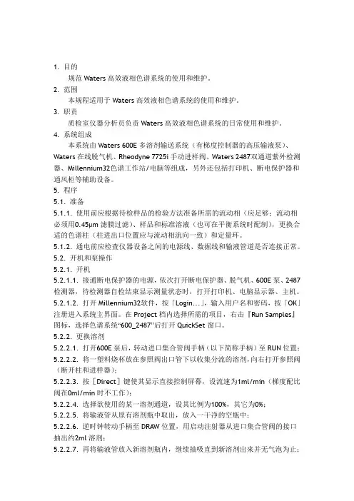
1. 目的规范Waters高效液相色谱系统的使用和维护。
2. 范围本规程适用于Waters高效液相色谱系统的使用和维护。
3. 职责质检室仪器分析员负责Waters高效液相色谱系统的日常使用和维护。
4. 系统组成本系统由Waters 600E多溶剂输送系统(有梯度控制器的高压输液泵)、Waters在线脱气机、Rheodyne 7725i手动进样阀、Waters 2487双通道紫外检测器、Millennium32色谱工作站/电脑等组成,另外还包括打印机、断电保护器和通风柜等辅助设备。
5. 程序5.1. 准备5.1.1. 使用前应根据待检样品的检验方法准备所需的流动相(应足够;流动相必须用0.45μm滤膜过滤)、样品和标准溶液(也可在平衡系统时配制),更换合适的色谱柱(柱进出口位置应与流动相流向一致)和定量环。
5.1.2. 通电前应检查仪器设备之间的电源线、数据线和输液管道是否连接正常。
5.2. 开机和泵操作5.2.1. 开机5.2.1.1. 接通断电保护器的电源,依次打开断电保护器、脱气机、600E泵、2487检测器,待检测器自检结束显示测量状态时,打开打印机、电脑显示器、主机。
5.2.1.2. 打开Millennium32软件,按「Login...」,输入用户名和密码,按「OK」注册进入系统主界面。
在Project档内选择所需的项目,右击『Run Samples』图标,选择色谱系统“600_2487”后打开QuickSet窗口。
5.2.2. 更换溶剂5.2.2.1. 打开600E泵后,转动进口集合管阀手柄(以下简称手柄)至RUN位置;5.2.2.2. 将一塑料烧杯放在参照阀出口管下以收集分流的溶剂,向右打开参照阀(断开柱和进样器);5.2.2.3. 按[Direct]键使其显示直接控制屏幕,设流速为1ml/min(梯度配比阀在0ml/min时不工作);5.2.2.4. 选择欲使用的某一溶剂通道,设其比例为100%,其它为0%;5.2.2.5. 将输液管从原有溶剂瓶中取出,放入一干净的空瓶中;5.2.2.6. 逆时钟转动手柄至DRAW位置,用启动注射器从进口集合管阀的接口抽出约2ml溶剂;5.2.2.7. 再将输液管放入新溶剂瓶内,继续抽吸直到新溶剂出来并无气泡为止;5.2.2.8. 转动手柄至RUN位置,将启动注射器取下并排掉筒内的溶剂。
SW6-1998过程设备强度计算软件包》的编制单位包括:全国化工设备设计技术中心站、华东理工大学化工机械研究所、中国石化集团上海工程有限公司(原上海医药设计院)、中国寰球工程公司、中国天辰化学工程公司、五环科技股份有限公司(原化四院)、华陆工程科技有限责任公司(原化六院)、天津市化工设计院和合肥通用机械研究所等国内长期从事化工与石油化工工程设计和计算机程序开发工作的单位。
本软件包能紧跟计算机技术的飞速发展,在确保计算结果正确、快捷的前提下,让用户在操作使用时更直观、方便和灵活,符合使用Windows的习惯。
1、SW6-1998包括有十个设备计算程序(分别为卧式容器、塔器、固定管板换热器、浮头式换热器、填函式换热器、U形管换热器、带夹套立式容器、球形储罐、高压容器及非圆形容器等),以及零部件计算程序和用户材料数据库管理程序。
2、零部件计算程序可单独计算最为常用的受内、外压的圆筒和各种封头,以及开孔补强、法兰等受压元件,也可对HG20582-1998《钢制化工容器强度计算规定》中的一些较为特殊的受压元件进行强度计算。
十个设备计算程序则几乎能对该类设备各种结构组合的受压元件进行逐个计算或整体计算。
3、由于SW6-1998以Windows为操作平台,不少操作借鉴了类似于Windows的用户界面,因而允许用户分多次输入同一台设备的原始数据、在同一台设备中对不同零部件原始数据的输入次序不作限制、输入原始数据时还可借助于示意图或帮助按钮给出提示等,极大地方便用户使用。
一个设备中各个零部件的计算次序,既可由用户自行决定,也可由程序来决定,十分灵活。
4、为了便于用户对图纸和计算结果进行校核,并符合压力容器管理制度原始数据存档的要求,在本次发布的版本中新增了一个功能——打印用户输入的原始数据。
5、计算结束后,分别以屏幕显示简要结果及直接采用WORD表格形式形成按中、英文编排的《设计计算书》等多种方式,给出相应的计算结果,满足用户查阅简要结论或输出正式文件存档的不同需要。
CHEMICALENGINEERINGDESIGN化工设计2021,31(2)带颈对焊法兰设计注意事项魏宝锋 上海寰球工程有限公司 上海 200032摘要 本文介绍带颈对焊法兰设计的注意事项,重点阐述两种确定法兰对接段壁厚的方法,说明两种方法的适用情况和具体措施,为今后的类似设计提供借鉴。
关键词 法兰材料 法兰环 锥段 对接段魏宝峰:工程师。
2005年6月毕业于江苏工业学院过程装备与控制工程专业。
从事非标设备设计。
联系电话:15821249338,E-mail:weibaofeng-hqc@cnpc com cn。
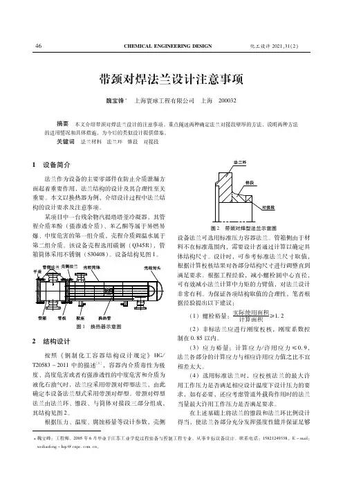
1 设备简介法兰作为设备的主要零部件在防止介质泄漏方面起着重要作用,法兰结构的设计及其合理性至关重要。
本文以换热器为例,介绍设计过程中法兰结构的设计要求及注意事项。
某项目中一台残余物汽提塔塔釜冷凝器,其管程介质苯酚(强渗透介质)、苯乙酮等属于易燃易爆、中度危害的第一组介质,壳程介质调温水属于第二组介质。
该设备壳程选用碳钢(Q345R),管箱筒体采用不锈钢(S30408)。
设备结构见图1。
图1 换热器示意图2 结构设计按照《钢制化工容器结构设计规定》HG/T20583-2011中的描述[1],容器内介质毒性为极度、高度危害或者有强渗透性的中度危害和介质为液化石油气时,法兰应采用带颈对焊型法兰,由此确定本设备法兰型式采用带颈对焊型。
带颈对焊型法兰由法兰环、锥段、与筒体对接段三部分组成,其结构见图2。
根据压力、温度、腐蚀裕量等设计参数,壳侧图2 带颈对焊型法兰示意图设备法兰可选用标准压力容器法兰。
管箱侧由于材料不在标准范围内,需要设计者通过计算以确定具体结构尺寸。
设计时,可参考标准法兰尺寸取值,根据计算校核结果对各部分结构尺寸进行调整直到满足要求。
根据工程经验,减小螺栓圆中心直径,可有效减小法兰计算中力矩的力臂值,对法兰设计非常有利。
为保证各项结构取值的合理性,笔者根据经验提出以下建议:(1)螺栓裕量:实际使用面积计算面积≥12(2)非标法兰应进行刚度校核,刚度系数控制在0 85以内。
三维球的使用有些人称赞三维球是CAD(计算机辅助设计)历史上最有用的工具。
它是CAXA实体设计的一个强大而灵活的三维空间定位工具。
虽然本文所列举的大部分例子都是讲解如何放置单独的零件,但是三维球在CAXA实体设计中还有许多其它的用途,包括:●装配定位●零件定位●特征定位●直接表面造型●剖切面定位●键盘动画路径控制●放样和扫描路径控制●纹理绘图布置●视向定位●点和聚光灯定位●锚状图标定位●附着点定位本文的目的是通过举例,演示三维球的一些较为高级的功能。
在此假定读者对《CAXA实体设计用户指南》第9章所介绍的三维球基本功能已有相当程度的了解。
这些例子需要使用2个文件,即“triball1.ics”和“triball2.ics”。
本文的标题包括:●使用三维球的中心控制柄●使用三维球的内侧“定向控制柄”●使用空格键对三维球进行分离和重新定位●暂时约束三维球的一条轴线●用三维球进行捕捉范围设置●使用三维球复制圆形/线性阵列模式●到点命令●点到点命令●与边平行命令●与面垂直命令●到中心点命令●与轴平行命令●反转命令三维球的构造三维球的键盘命令:F10 打开/关闭三维球 空格键将三维球分离/附着于选定的对象Ctrl在平移/旋转操作中激活增量捕捉三维球的工具按钮:打开教程文件1. 从C:\CAXASolid\Tutorials 路径下打开文件triball1.ics 。
2. 选择图中所示的轴体,然后打开三维球。
外控制柄 - 主要用来进行轴线上的线性平移 ,或指定旋转轴线。
也可以在使用其它三维球特征前,用来对轴线进行暂时的约束。
圆周 - 拖动这里,可以围绕从视点延伸到三维球中心的一条虚拟轴线旋转。
内侧 - 在这个空白区域内侧拖动进行旋转。
也可以右键点击这里,进行各种三维球选项的设中心控制柄 - 主要用来进行点到点的平移。
使用的方法是将它直接拖至另一个目标位置,或右键点击,然后从弹出的菜单中挑选一个选项。
它还适合与约束二维平面 - 拖动这里在选定的虚拟平面中自由移动。
思拓力S9/S6系列RTK软件操作流程呼和浩特市北半球测绘仪器有限公司思拓力RTK操作步骤一.新建工程P7手簿采用的Moble的系统,开机的系统界面如下图:我们点击开始菜单,在开始菜单的列表里选择我们的手簿软件SurPad2.0,如下图:打开软件后点击-新建,如下图:输入新建工程名称,默认的是手簿系统时间,输入时点击会切换出软件盘,也可以用键盘输入,输入完成后点对勾点确定:确定之后会来到我们连接仪器的界面如下图:仪器型号选择S9/S6,点击蓝牙如下图:如果手簿里有你的仪器号和对应的COM 口这直接选择并点确定,如果没有那么我们需要给手簿配置一下蓝牙,点击“配置蓝牙设备”如下图:点击添加新设备,让手簿搜索你的主机蓝牙号,如下图:搜索到你的主机蓝牙号后选中点击下一步,输入密码1234,点击下一步,如下图:软件提示已建立连接,点击完成,如下图:点击端口选项,为主机蓝牙配置端口,如下图:点击新建端口,选中我们的主机号,点击下一步,如下图:选择一个端口,点击完成,如果提示无法创建端口,点击OK,重新选择另外能用的端口,如下图:创建好能端口后,点击OK,在蓝牙列表里选择主机的仪器号后点击确定,如下图:然后点击连接,手簿开始连接仪器,如下图:连接变为断开说明已经连接上仪器,然后点击关闭,点击关闭后到了设置你新建工程的坐标系统参数的界面,如下图:在这里我们首先设置椭球参数,点击椭球参数,在下拉列表里选择你控制点坐标系统的椭球,如国家80,如下图:选择好后点击确定,然后设置投影参数,点击投影参数,在下拉列表里选择你的投影方式,一般为高斯投影,这里没有六度和三度之分,高斯投影已涵盖了。
然后设置你的中央子午线经度,如果知道直接输入,如果你是三度带的话,不知道当地的中央子午线,点击旁边的A,软件会自动算出并添加(这里是指手簿连上仪器,并且仪器应经锁定卫星的情况),六度带和自定义只能自己添加了,如下图:点击确定,在点击确定,然后选择工程测量,点击关闭,如下图:到这里,新建工程,就建好了,如果你是提前建工程的话,那么连接仪器就可以省略了,出来设置仪器的时候在进行连接,在通讯设置里连接就可以了。
WES-600型数显万能试验机操作规程1、打开数显表上的电源开关,接通电源。
2、根据试样,选择测量范围。
3、根据试样规格,选择相应的试验夹具,如做拉伸试验,则把相应的夹头装入上下钳口内。
4、关闭送油阀和回油阀手轮。
5按油泵电机启动钮,油泵供油。
6开启送油阀手轮,使试台升起5-10毫米,然后关闭送油阀。
如果已在升起位置,送油阀关闭好即可。
7、将试样一端装入上钳口内并加紧。
8、开动移动横梁电机,将下钳口升(降)至合适位置,将试样另一端夹在下钳口内,注意式样必须铅垂,并在中间位置。
9打开送油阀,按所需要的加荷速度,人为手动控制,时刻注意试样和数显表读数的变化。
10、在加压过程中,当位移继续而力值显示不再增加甚至下降时,说明试样已经断裂或破坏,关闭送油阀,打开回油阀卸荷。
11、取下断裂后的试样,关闭油泵电机。
12、试验结束,打印出试验报告WES-300B型数显液压万能试验机操作规程1、打开数显表上的电源开关,接通电源。
2、根据试样,选择测量范围。
3、根据试样规格,选择相应的试验夹具,如做拉伸试验,则把相应的夹头装入上下钳口内。
4、关闭送油阀和回油阀手轮。
5按油泵电机启动钮,油泵供油。
6开启送油阀手轮,使试台升起5-10毫米,然后关闭送油阀。
如果已在升起位置,送油阀关闭好即可。
7、将试样一端装入上钳口内并加紧。
8、开动移动横梁电机,将下钳口升(降)至合适位置,将试样另一端夹在下钳口内,注意式样必须铅垂,并在中间位置。
9打开送油阀,按所需要的加荷速度,人为手动控制,时刻注意试样和数显表读数的变化。
10、在加压过程中,当位移继续而力值显示不再增加甚至下降时,说明试样已经断裂或破坏,关闭送油阀,打开回油阀卸荷。
11、取下断裂后的试样,关闭油泵电机。
12、试验结束,打印出试验报告TYE-2000B型数字式压力试验机操作规程1、接通电源,红色指示灯亮,如不亮,则顺时针旋转电源开关。
2、选定合适的档位。
3、按“设置”键,进行系统设置(编号、龄期等),如不需调整,直接进行下一步操作。
珠承全轴摆动喷管阳球使用指南和注意事项下载温馨提示:该文档是我店铺精心编制而成,希望大家下载以后,能够帮助大家解决实际的问题。
文档下载后可定制随意修改,请根据实际需要进行相应的调整和使用,谢谢!并且,本店铺为大家提供各种各样类型的实用资料,如教育随笔、日记赏析、句子摘抄、古诗大全、经典美文、话题作文、工作总结、词语解析、文案摘录、其他资料等等,如想了解不同资料格式和写法,敬请关注!Download tips: This document is carefully compiled by theeditor.I hope that after you download them,they can help yousolve practical problems. The document can be customized andmodified after downloading,please adjust and use it according toactual needs, thank you!In addition, our shop provides you with various types ofpractical materials,such as educational essays, diaryappreciation,sentence excerpts,ancient poems,classic articles,topic composition,work summary,word parsing,copy excerpts,other materials and so on,want to know different data formats andwriting methods,please pay attention!珠承全轴摆动喷管阳球使用指南与安全注意事项一、珠承全轴摆动喷管阳球简介珠承全轴摆动喷管阳球是一种先进的机械设备,广泛应用于各种工业生产中,如喷涂、清洗等工艺。