欧姆龙时间继电器h3de
- 格式:pdf
- 大小:2.25 MB
- 文档页数:21


125VDE123654GU (General Use)-E Type[1-Channel (Form B) Type]mm inch8.8±0.05.346±.0026.4±0.05.252±.0023.6±0.2.142±.0088.8±0.05.346±.0026.4±0.05.252±.0023.9±0.2.154±.008 FEATURES1. Low on resistance for normally-closed typeThis has been realized thanks to the built-in MOSFET processed by our proprietary method, DSD (Double-diffused and Se-lective Doping) method.Source electrode Gate electrodePassivation membraneCross section of the normally-closed type of power MOSIntermediate insulating membraneGateoxidation membraneDrain electrode2. Controls low-level analog signals PhotoMOS relays feature extremely low closed-circuit offset voltage to enable control of low-level analog signals without distortion.3. High sensitivity, low ON resistance Can control a maximum 0.13 A load cur-rent with a 5 mA input current. Low ON re-sistance of 18 Ω (AQV410EH). Stable operation because there are no metallic contact parts.4. Low-level off state leakage current The SSR has an off state leakage current of several milliamperes, whereas the Pho-toMOS relay has only 100 pA even with the rated load voltage of 400 V (AQV414E).5. Reinforced insulation 5,000 V type also available.More than 0.4 mm internal insulation dis-tance between inputs and outputs. Con-forms to EN41003, EN60950 (reinforced insulation).TYPICAL APPLICATIONS• Security equipment• T elepone equipment (Dial pulse)• Measuring equipmentTYPES*Indicate the peak AC and DC values.Note: For space reasons, the package type indicator "X" and "Z" are omitted from the seal.TypeI/O isolation voltageOutput rating*Part No.Packing quantityThrough hole terminalSurface-mount terminalLoad voltage Load current Tube packing style T ape and reel packing style T ube T ape and reelPicked from the 1/2/3-pin side Picked from the 4/5/6-pin side AC/DC type 1,500 V AC(Standard)400 V 120 mA AQV414E AQV414EA AQV414EAX AQV414EAZ 1 tube contains50 pcs.1 batch contains500 pcs.1,000 pcs.5,000 V AC(Reinforced)350 V 130 mA AQV410EH AQV410EHA AQV410EHAX AQV410EHAZ 400 V120 mAAQV414EHAQV414EHAAQV414EHAXAQV414EHAZRATING1. Absolute maximum ratings (Ambient temperature: 25 ° C 77 ° F )ItemSymbol Type of connectionAQV414E(A)AQV410EH(A)AQV414EH(A)RemarksInputLED forward current I F 50 mA LED reverse voltage V R 3 V Peak forwrd current I FP 1 A f = 100 Hz, Duty factor = 0.1%Power dissipationP in 75 mW OutputLoad voltage (peak AC)V L 400 V 350 V 400 V Continuous load currentI LA 0.12 A 0.13 A 0.12 A A connection: Peak AC, DC B,C connection: DCB 0.13 A 0.15 A 0.13 AC 0.15 A 0.17 A 0.15 A Peak load currentI peak 0.3 A0.4 A 0.3 AA connection: 100 ms (1 shot), V L = DCPower dissipationP out 500 mW Total power dissipation P T 550 mW I/O isolation voltage V iso 1,500 V AC 5,000 V AC5,000 V ACTemperature limitsOperating Topr –40 ° C to +85 ° C –40 ° F to +185 ° F Non-condensing at low temperaturesStorageTstg –40 ° C to +100 ° C –40 ° F to +212 °FPhotoMOS RELAYS查询AQV410供应商AQV414E, AQV41 r EH1262. Electrical characteristics (Ambient temperature: 25 ° C 77 ° F )For type of connection, see Page 32.Note:Recommendable LED forward currentStandard type I F = 5 mAReinforced type I F = 5 to 10 mA *Operate/Reverse timeItemSymbol T ype ofconnec-tion AQV414E(A)AQV410EH(A)AQV414EH(A)Condition InputLED operate (OFF) currentTypical I Foff — 1.45 mA1.9 mA 1.75 mA I L = Max.Maximum 3.0 mALED reverse (ON) current Minimum I Fon —0.3 mA 0.4 mA 0.3 mA I L = Max.Typical 1.40 mA 1.8 mA 1.70 mALED dropout voltageTypical V F — 1.14 V (1.25 V at I F = 50 mA)I F = 5 mAMaximum 1.5 VOutputOn resistanceTypical RonA26 Ω 18 Ω 25.2 Ω I F = 0 mA IL = Max.Within 1 s on time Maximum 50 Ω 35 Ω 50 Ω TypicalRonB20 Ω 13 Ω 19 Ω I F = 0 mA IL = Max.Within 1 s on time Maximum25 Ω 17.5 Ω 25 Ω Typical Ron C 10 Ω 6.5 Ω 10 Ω I F = 0 mA IL = Max.Within 1 s on time Maximum12.5 Ω 8.8 Ω 12.5 Ω Off state leakage currentMaximum ILeak — 1 µ A 10 µ A 10 µ A I F = 5 mA V L = Max.T ransfercharacteristicsSwitching speedOperate (OFF) time*Typical T off —0.7 ms 1.5 ms 1.3 ms IF = 0 mA ¨ 5 mA I L = Max.Maximum 2.0 ms 3.0 ms 3.0 ms Reverse (ON) time*Typical T on —0.1 ms 0.3 ms 0.3 ms IF = 5 mA ¨ 0 mA I L = Max.Maximum 1.0 ms 1.5 ms 1.5 ms I/O capacitance Typical C iso —0.8 pF0.8 pF 0.8 pFf = 1 MHz V B = 0Maximum 1.5 pF Initial I/O isolation resistanceMinimumRiso—1,000 M Ω500 V DCs For Dimensions, see Page 27.s For Schematic and Wiring Diagrams, see Page 32. s For Cautions for Use, see Page 36.REFERENCE DATA1. Load current vs. ambient temperature char-acteristicsAllowable ambient temperature:–40 ° C to +85 ° C–40 ° F to +185 ° FType of connection: A2. On resistance vs. ambient temperature char-acteristicsMeasured portion: between terminals 4 and 6;LED current: 0 mA; Load voltage: Max. (DC);Continuous load current: Max. (DC)3. Operate (OFF) time vs. ambient temperature characteristicsLED current: 5mA; Load voltage: Max. (DC);Continuous load current: Max. (DC)Ambient temperature, °CL o a d c u r r e n t , m A Ambient temperature, °CO n r e s i s t a n c e , Ω1020304050Ambient temperature, °CO p e r a t e (O F F ) t i m e , m s02.03.05.01.04.0AQV414E, AQV41 r EH4. Reverse (ON) time vs. ambient temperature characteristicsLED current: 5 mA; Load voltage: Max. (DC);Continuous load current: Max. (DC)5. LED operate (OFF) current vs. ambient tem-perature characteristicsLoad voltage: Max. (DC);Continuous load current: Max. (DC)6. LED reverse (ON) current vs. ambient tem-perature characteristicsLoad voltage: Max. (DC);Continuous load current: Max. (DC)Ambient temperature, °CR e v e r s e (O N ) t i m e , m s0.80.60.40.2Ambient temperature, °CL E D o p e r a t e (O F F ) c u r r e m t , m A12345Ambient temperature, °CE D r e v e r s e (O N ) c u r r e n t , m A。

公司是欧姆龙一级代理商,价格优势明显,质量有保证,有大量库存,供货期短。
欢迎新老客户来电查询联系人:1 3 5 2 0 1 1 5 8 9 1 传0 1 0- 8 0 1 1 5 5 5 5转7 5 9 7 1 13F88L-RS173G3IV-PLKEB45P53G3JV-MANUAL3G3JZ-AB0223G3MV-A4075(YES)3G3MZ-A2004-ZV23G3MZ-A2007-ZV23G3MZ-A2015-ZV23G3MZ-A2055-ZV23G3RV-B418K-ZV13G3RV-B422K-ZV13G3RV-B4900-ZV13G3RX-A4220-Z43767-0010 MC374005-3066 UM5-3066C200H-ATT01C200H-BC101-V2C200H-CP114C200H-DA001C200H-DA002C200H-ID218C200H-ID501C200H-NC111C200H-OD501C200H-TS001C200HW-COM01C200HW-COM05-EV1C200HW-DRM21-V1C200HW-NC213C500-CE405CJ1W-OD263CP1W-20EDT1(Q)CP1W-40EDT1CPM1A-20EDT1CPM1A-40CDT-A-V1 CPM2A-20CDR-DCPM2A-20CDT-DCPM2A-30CDR-DCQM1-ID211CQM1-ME04RCQM1H-PLB21CRT1-AD04CS1D-CPU44SCS1H-CPU66HCS1H-CPU67HCS1W-BAT01CS1W-BI033CS1W-CN224CS1W-OC201CS1W-PDC55CS1W-SCU31-V1D4N-212GDRT1-232C2DRT2-AD04E2E-X10D1S DC12-24 2ME3X-DAC21-S 2ME5AZ-C3E5AZ-Q3E5AZ-R3E5CN-Q2HBT AC100-240 (Q)E5CN-R2HBT AC100-240 (Q)E5CN-R2T AC100-240 (Q)E5CZ-Q2 AC100-240E5CZ-R2MT AC100-240E5EZ-C3E6C2-CWZ6C 1024P/R 2M BY OMSG3JA-C425B AC100-240 FOR CHINA G3JA-C430B AC100-240 FOR CHINA G3JA-C437B AC100-240 FOR CHINA G3JA-D420B AC100-240 FOR CHINA G3JA-D425B AC100-240 FOR CHINA G3JA-D432B AC100-240 FOR CHINA G3JA-D451B AC100-240 FOR CHINA G3PB-535B-2N-VD DC12-24H5CN-XCN AC100-240H5F-BMKS2P DC12MKS3P-5 DC48MPT-CN550NS10-TV01B-V2R7A-CNB01S-ZR7A-CNB01SB-ZR7A-CNZ01C-ZR7D-AP04HR7D-AP08HR7D-BP01H-ZR7D-BP02H-ZR7D-BP02HH-ZR7D-BP04H-ZR7D-ZP01HR7D-ZP02HR7M-A40030-S1R7M-A75030-S1R7M-Z10030-S1ZR7M-Z20030-S1ZR88A-CNG01SB-ZR88D-GN01H-ML2-ZR88D-GN02H-ML2-ZR88D-GN04H-ML2-ZR88D-GN08H-ML2-ZR88D-GN10H-ML2-ZR88D-GN15H-ML2-ZR88D-GN20H-ML2-ZR88D-GN50H-ML2-ZR88D-GN75H-ML2-ZR88D-GT50H-ZR88D-GT75H-ZR88D-WN08H-ML2R88D-WN10H-ML2R88M-G10030H-BS2-Z R88M-G10030H-ZR88M-G1K020H-S2-Z R88M-G1K020H-ZR88M-G1K020T-BS2-Z R88M-G1K020T-S2-Z R88M-G1K020T-ZR88M-G1K030H-BS2-Z R88M-G1K030H-S2-Z R88M-G1K030H-ZR88M-G1K030T-S2-Z R88M-G1K520H-BS2-Z R88M-G1K520H-S2-Z R88M-G1K520H-ZR88M-G1K520T-BS2-Z R88M-G1K520T-S2-Z R88M-G1K520T-ZR88M-G1K530H-S2-Z R88M-G1K530T-S2-Z R88M-G20030H-BS2-Z R88M-G20030T-BS2-Z R88M-G20030T-S2-Z R88M-G2K010H-S2-Z R88M-G2K010H-ZR88M-G2K010T-S2-Z R88M-G2K010T-ZR88M-G2K020H-BS2-Z R88M-G2K020H-S2-Z R88M-G2K020H-ZR88M-G2K020T-S2-ZR88M-G2K030H-S2-Z R88M-G2K030T-S2-Z R88M-G3K010H-BS2-Z R88M-G3K010H-S2-Z R88M-G3K010H-ZR88M-G3K010T-S2-Z R88M-G3K020H-BS2-Z R88M-G3K020H-S2-Z R88M-G3K020H-ZR88M-G3K020T-S2-Z R88M-G3K020T-ZR88M-G3K030H-BS2-Z R88M-G3K030H-S2-Z R88M-G3K030H-ZR88M-G40030H-B-ZR88M-G40030H-BS2-Z R88M-G40030H-ZR88M-G40030T-BS2-Z R88M-G40030T-S2-Z R88M-G4K020H-BS2-Z R88M-G4K020H-S2-Z R88M-G4K020T-S2-Z R88M-G4K030H-BS2-Z R88M-G4K030H-S2-Z R88M-G4K510H-BS2-Z R88M-G4K510H-S2-Z R88M-G4K510T-S2-Z R88M-G5K020H-BS2-ZR88M-G5K030H-BS2-ZR88M-G5K030H-S2-ZR88M-G6K010H-BS2-ZR88M-G6K010H-S2-ZR88M-G75030H-BS2-ZR88M-G75030T-BS2-ZR88M-G75030T-S2-ZR88M-G7K515H-BS2-ZR88M-G7K515H-S2-ZR88M-G7K515T-S2-ZR88M-G90010T-S2-ZR88M-GP10030H-ZR88M-GP40030H-ZR88M-W10030T-S1SH-001-01MSH-001-03MSH-001-05MSH-001-10MV400-W23 3MV400-W24 3MWLCA32-41ZR-RX20A-CHROZR-RX40A-CHROZR-XRB1ZR-XRE1我公司是欧姆龙一级代理商,价格优势明显,质量有保证,有大量库存,供货期短。

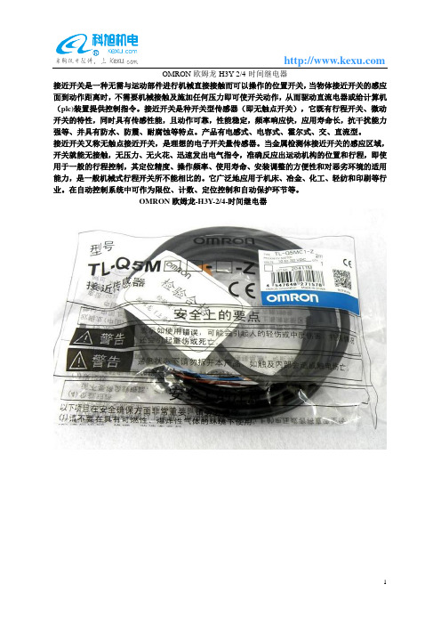
OMRON欧姆龙-H3Y-2/4-时间继电器
接近开关是一种无需与运动部件进行机械直接接触而可以操作的位置开关,当物体接近开关的感应面到动作距离时,不需要机械接触及施加任何压力即可使开关动作,从而驱动直流电器或给计算机(plc)装置提供控制指令。
接近开关是种开关型传感器(即无触点开关),它既有行程开关、微动开关的特性,同时具有传感性能,且动作可靠,性能稳定,频率响应快,应用寿命长,抗干扰能力强等、并具有防水、防震、耐腐蚀等特点。
产品有电感式、电容式、霍尔式、交、直流型。
接近开关又称无触点接近开关,是理想的电子开关量传感器。
当金属检测体接近开关的感应区域,开关就能无接触,无压力、无火花、迅速发出电气指令,准确反应出运动机构的位置和行程,即使用于一般的行程控制,其定位精度、操作频率、使用寿命、安装调整的方便性和对恶劣环境的适用能力,是一般机械式行程开关所不能相比的。
它广泛地应用于机床、冶金、化工、轻纺和印刷等行业。
在自动控制系统中可作为限位、计数、定位控制和自动保护环节等。
OMRON欧姆龙-H3Y-2/4-时间继电器。
Solid-state Timer H3DE DIN Track Mounted, Standard 22.5-mm Width Timer RangeA wide AC/DC power supply range (24 to 230 VAC/DC) reduces the number of timer models kept in stock.(except for H3DE-H)12-VDC model available for a specific application. (H3DE-M2)Nameplate provided for easy timer identification and management.Terminal clamp left open when delivered.Finger protection terminal block to meet VDE0106/P100.Enables easy sequence checks through instantaneous outputs for a zero set value at any time range.Incorporates environment-friendly, cadmium-free contacts. (except for H3DE-H)High immunity to inverter noise.Approved by UL and CSA.Conforms to EN61812-1 and IEC60664-1 (VDE0110) 4 kV/2 for Low Voltage and EMC Directives.H3DEStandard TimerH3DE-MH3DE-STwin TimerH3DE-FStar-delta TimerH3DE-GPower OFF-delay TimerH3DE-H H3DE-M/S H3DE-F H3DE-G H3DE-HContentsSolid-state TimerH3DE-M/S5. . . . . . . . . . . . . . . . . . . . . . . . . . . . . . . . . . . . . . . . . . . . . . . . . . . . . . . . . .H3DE-F14. . . . . . . . . . . . . . . . . . . . . . . . . . . . . . . . . . . . . . . . . . . . . . . . . . . . . . . . . . . .H3DE-G20. . . . . . . . . . . . . . . . . . . . . . . . . . . . . . . . . . . . . . . . . . . . . . . . . . . . . . . . . . . .H3DE-H26. . . . . . . . . . . . . . . . . . . . . . . . . . . . . . . . . . . . . . . . . . . . . . . . . . . . . . . . . . . .Common to ALL TimersAccessories32. . . . . . . . . . . . . . . . . . . . . . . . . . . . . . . . . . . . . . . . . . . . . . . . . . . . . . . .Precautions33. . . . . . . . . . . . . . . . . . . . . . . . . . . . . . . . . . . . . . . . . . . . . . . . . . . . . . . . .Solid-state Multi-functional Timer H3DE-M/-S Eight operating modes (H3DE-M) and fouroperating modes (H3DE-S) cover a wide range ofapplications.Programmable contact enables the building of aself-holding relay circuit (-j2 models).A wide time setting range of 0.10 s to 120 h.Note:Can be mounted to 35-mm DIN track with a plate thickness of 1 to 2.5 mm.Note:When the main dial is set to “0” for all settings, the output will operate instantaneously.RatingsNote: 1.DC ripple rate: 20% max.2.Since an inrush current of 0.25 A will occur when using the power supply voltage at 24 VDC, pay careful attention when turning on oroff the power supply to the T imer with a solid-state output such as a sensor.3.The power consumption is for mode A after the T imer counts the time-up time and for the AC input at 50 Hz. The power consumptionof the H3DE-M j includes the input circuit with the B1 and A1 terminals short-circuited.CharacteristicsNote: 1.With the H3DE-M j, if the voltage exceeds 26.4 V AC/DC, the following hold at signal OFF for C, D, and G modes: Accuracy of operating time: ±1% ±50 ms max. at 1.2-s rangeSetting error: ±10% +100/–50 ms max.Signal input time: 100 ms min.2.For reference : A maximum current of 0.15 A can be switched at 125 VDC (cosφ=1).A maximum current of 0.1 A can be switched if L/R is 7 ms.In both cases, a life of 100,000 operations can be expected.The minimum applicable load is 10 mA at 5 VDC (failure level: P).Output type selector switch for H3DE-M2/-S2 (default setting is time-limit output)Setting Output typeTime-limit output (terminal numbers 25, 26 and28) (default setting)Instantaneous output(terminal numbers 21, 22 and 24)Output Type Selector Switch Settings(Bottom View)H3DE-S1/-S2I/O FunctionsNote:When the output type selector switch on the bottom of the T imer is set to the instantaneous side, the relay R2 (terminal numbers 21/25,22/26, and 24/28) becomes an instantaneous contact and turns ON/OFF in synchronization with the changes in the power supply .Setting of SelectorThe selectors can be turned clockwise and counterclockwise to se -lect the desired time unit, time scale, or operating mode.Each selector has a snap mechanism that secures the selector at a given position. Set the selector at a position at which it is secured.Do not set it midway between two securing positions or a malfunc -tion could result from improper setting.Operating mode selectorOperating mode display windowSelection of Operating ModeThe H3DE-M/-S can be set to any one of the operating modes A to J.Turn the operating mode selector with a screwdriver until the de-sired operating mode (A, B, C, B2, D, E, J, or G for the H3DE-M and A, E, J, or B2for the H3DE-S) appears in the operating mode display window located below the selector .Selection of T ime Unit and T ime ScaleThe desired time unit (s, m, h, or 10h) can be displayed in the time unit display window above the time setting dial by turning the time unit selector located at the upper right corner of the front panel. T ime scale (0.1 or 1) is selected with the time scale selector at the upper left corner of the front panel, it appears in the time scale display win -dow above the selector .T ime unit selectorNote: 1.The minimum power reset time is 0.1 s and the minimum signal input time is 0.05 s.2.The letter “t” in the timing charts stands for the set time and “t–a” means that the period is less than the time set.tFor power-on operation, impose voltage to theStart input. The Timer starts operating at themoment the power is turned on.Start input is invalid while the Timer is in opera-tion.**Basic operationt t t tFor power-on operation, impose voltage to theStart input. The Timer starts operating at themoment the power is turned on.Start input is invalid while the Timer is in opera-tion.**Basic operationOutputt t t tFor power-on operation, impose voltage to theStart input. The Timer starts operating at themoment the power is turned on.Start input is invalid while the Timer is in opera-tion.**Basic operationOutputtt t tStart input is invalid while the Timer is in opera-tion.*Note:The start input of the H3DE-M1 or H3DE-M2 model is activated by applying a voltage to B1 and A2 terminals.The voltage can be applied by turning on the contact between B1 and A1 (Refer to T erminal Arrangement).tStart input is valid and re-triggerable while theTimer is in operation.*tBasic operationFor power-on operation, impose voltage to theStart input. The Timer starts operating at themoment the power is turned on.Start input is valid and re-triggerable while theTimer is in operation.**Basic operationt t t t*t t tt–a t–aApprox. 1±0.6 s (fixed)Approx.1±0.6 s(fixed) Approx.1±0.6 s(fixed)Note:The start input of the H3DE-M1 or H3DE-M2 model is activated by applying a voltage to B1 and A2 terminals.The voltage can be applied by turning on the contact between B1 and A1 (Refer to T erminal Arrangement).H3DE-M/-STerminal block (black)Surface color:Light gray 5Y7/1 (OMRON)Output type selector switch (default setting: Time-limit output) 15R118161816A2B1A115(see note 2)(see note 2)(see note 2)(see note 2)------------------------------------------------------------------------------------------------------------------------------------------------------------------------------------------------------------------------------------------------------Note: 1.The relay R2 can be set to either instantaneous or time-limit contact using the switch located on the bottom of the T imer.2.DC supply voltage does not require the designation of polarity.3.The contact symbol for the H3DE is indicated withThe inputs of the H3DE-M1/-M2 are voltage (voltage imposition or open) inputs.No-contact Input(Connection to PNP output sensor .)Contact InputV oltage Input Signal LevelsNo-contact inputContact input1. T ransistor ONResidual voltage: 1 V max.(V oltage between terminals B 1 and A 2 must be more than the rated “H-level” voltage (20.4 VDC min.).)2. T ransistor OFFLeakage current: 0.01 mA max.(V oltage between terminals B 1 and A 2 must be less than the rated “L-level” voltage (2.4 VDC max.).)Use contacts that can adequately switch 0.1 mA at each voltage to be imposed. (When the contacts are ON orOFF , voltage between terminals B 1 and A 2 must be within the following ranges:When contacts are ON:20.4 to 253 V AC/DC When contacts are OFF:0 to 2.4 V AC/DCOperates with PNP transistor ONOperates with relay ONNo-contact Input(Connection to NPN output sensor .)SensorA 1B 1A 224 VDC (+)(–)Operates with NPN transistor ONTimerSolid-state Twin Timer H3DE-F Operates in flicker-OFF or flicker-ON start modewith one Unit.Independent ON- and OFF-time settings.Combinations of long ON- or OFF-time and shortOFF- or ON-time setting are possible.Long time range from 0.1 s to 12 h for both ON andOFF time settings.H3DE -11.F:Twin timersNote:Can be mounted to 35-mm DIN track with a plate thickness of 1 to 2.5 mm.Note: 1.T ime scale display is applied commonly for ON and OFF time.2.When the main dial is set to “0” for all settings, the output will operate instantaneously. RatingsNote:DC ripple rate: 20% max.CharacteristicsNote:For reference:A maximum current of 0.15 A can be switched at 125 VDC (cosφ=1).A maximum current of 0.1 A can be switched if L/R is 7 ms.In both cases, a life of 100,000 operations can be expected.The minimum applicable load is 10 mA at 5 VDC (failure level: P).Time scale display windowTime scale selector (select 0.1 or 1)Output ON indicator (orange)Output OFF indicator (green)Nameplate for user use (20 x 5.4 mm white panel)ON-time unit display windowTime unit selector(select one from s, 10s, min, or h for output ON)ON-time setting dial OFF-time setting dialOFF-time unit display windowON/OFF start selector(default is flicker-OFF start)OFF-time unit selector(select one from s, 10s, min, or h)Time Unit SelectionThe time unit display window for output ON is located on the upper-right side of the front panel above the corresponding time unit selec -tor.The time unit display window for output OFF is located on the lower-right side of the front panel belowthe corresponding time unit selec -tor.According to the setting of each time unit selector , “sec” for seconds,“10s” for 10 seconds, “min” for minutes, or “hrs” for hours will appear in the corresponding time unit display window .ON-time unit display window ON-time unit selector (select one from s, 10s, min, or h)OFF-time unit selector (select one from s, 10s, min, or h)OFF-time unit display windowTime Scale SelectionThe time scale selector on the upper-left side of the front panel can be set to 0.1 or 1 as a magnification coef ficient.Time scale display window Time scale selectorON-time setting dialOFF-time setting dialTime SettingUse the ON/OFF-time setting dial to set the ON/OFF time.t ON : ON set time t OFF : OFF set time0.1 s min.t ON : ON set time t OFF : OFF set time0.1 s min.Note: 1.The reset time requires a minimum of 0.1 s.2.When power is supplied in flicker-ON start mode, the OFF indicator lights momentarily . This, however , has no ef fect on the perfor -mance of the T imer.Terminal block (black)Surface color:Light gray 5Y7/1(OMRON)Terminal block (black)Note:DC supply voltage does not require the designation of polarity.Solid-state Star-delta Timer H3DE-G A wide star-time range (up to 120 seconds) andstar-delta transfer time range (up to 0.5 seconds)H3DE -11.G:Star-delta timerNote:Can be mounted to 35-mm DIN track with a plate thickness of 1 to 2.5 mm.RatingsNote:DC ripple rate: 20% max.CharacteristicsNote:For reference:A maximum current of 0.15 A can be switched at 125 VDC (cosφ=1).A maximum current of 0.1 A can be switched if L/R is 7 ms.In both cases, a life of 100,000 operations can be expected.The minimum applicable load is 10 mA at 5 VDC (failure level: P).Star operation indicator (green)Delta operation indicator (orange)Time setting dial (for setting star operation time)Star-delta transfer time selectorStar-delta transfer time display windowTime scale display window Star operation time scale selector (select 1 or 10)Nameplate for user use (20 x 5.4 mm white panel)(Front View)AC (DC) inputPower supply circuitStar operation indicator Delta operation indicatorIndicator circuitOutput circuitStar opera-tion time counting circuitStar-delta transfer timeselectionStar-delta transfer time oscilla-tion circuitStar-delta transfer time countingcircuitStar operationDelta operationStar opera-tion time oscillation circuit Staroperation time scale selectorTime Unit SettingThe star-delta transfer time is set to 0.05, 0.1, 0.25 or 0.5 with the star-delta transfer time selector on the lower-right side of the front panel and the set value appears in the star-delta transfer time dis -play window below the selector .Star-delta transfer time selectorStar-delta transfer time dis-play windowTime Scale SelectionThe star operation time scale selector on the upper-left side of the front panel can be set to 1 or 10 as a magnification.Star operation time scale display window Star operation time scale selectorTime setting dialTime SettingThe operation time of the T imer is set with the time setting dial.t 1: Star operation time setting t 2: Star-delta transfer time0.5 sNote:The reset time requires a maximum of 0.5 s.H3DE-GTerminal block (black)Surface color: Light gray 5Y7/1(OMRON)Terminal block (black)Note:DC supply voltage does not require the designation of polarity .Solid-state Power OFF-delay Timer H3DE-H Two delay-time models available.0.1 to 12 seconds (S Series)1 to 120 seconds (L Series)Covers wide range of supply voltage.Conforms to EMC Standard (EN50081-2 andEN50082-2).Note:Specify both the model number and supply voltage when ordering.Example: H3DE-H 24 V AC/DC ST ime span codeSupply voltageH3DE -11.H:Power OFF-delay timerNote:Can be mounted to 35-mm DIN track with a plate thickness of 1 to 2.5 mm.Note:The Timer will not operate if the specified power-on time is not kept. Be sure to supply power for at least the period specified. RatingsNote:The ripple in DC power supply must be 20% max. A single-phase, full-wave rectifying power supply can be connected if the ripple output of the power supply is a maximum of 20% of the whole output.CharacteristicsNote:For reference:A maximum current of 0.15 A can be switched at 125 VDC (cosφ=1).A maximum current of 0.1 A can be switched if L/R is 7 ms.In both cases, a life of 100,000 operations can be expected.The minimum applicable load is 100 mA at 5 VDC (failure level: P).Time scaledisplay window Time scale selectorS Series: Set to 0.1 or 1L Series: Set to 1 or 10Power indicator (green)Lit when the Timer is turned ON.Time setting dial (for setting power OFF-delay time)Nameplate for user use (20 x 5.4 mm white panel)(Front View)AC (DC) inputPower supply circuit Indicator circuit Output circuitPower failure detection circuitOscillation circuit Counting circuit Time scale selectorTime Scale SelectionThe time scale selector on the upper left-hand side of the front panel of the S Series can be set to 0.1 or 1 and that of the L Series can be set to 1 or 10 as magnification coef ficients.Time scale display windowTime scale selectorTime setting dialTime SettingThe operating time of the T imer is set with the time setting dial.Rt: Minimum power-on time (S-series: 0.1 s min.; L-series: 0.3 s min.)(The output may never turn ON if this time or more is not ensured.)H3DE-H Terminal block (black)Surface color:Light gray 5Y7/1(OMRON)Terminal block (black)Note:DC supply voltage does not require the designation of polarity.Note:All units are in millimeters unless otherwise indicated.Mounting TrackPFP-100N, PFP-50N PFP-100N2L: Length1 m PFP-100N50 cm PFP-50N1 m PFP-100N2End Plate PFP-M Spacer PFP-S4.51525252525*1010L 7.3±0.1535±0.327±0.1514.51525252525151010L35±0.327241629.21 1.55011.5M4 x 8pan headscrew 106.21.8135.535.31.81.34.85161244.316.51034.8NOTICE: Do not change the time unit, time scale, operating mode,or output type selector switch while the T imer is in opera -tion or malfunction could result.The H3DE should be mounted as horizontally as possible.When mounting the H3DE on a socket mounting track, hook portion (A) of the Timer to an edge of the track first, and then depress the T imer in the direction of (B).(B)When dismounting the H3DE, pull out portion (C) with a flat-blade screwdriver and remove the T imer from the mounting track.Rail stopperThe H3DE can be mounted and dismounted with ease if a distance of 30 mm or more is kept between the H3DE and the top surface of other equipment located below the H3DE.The H3DE Series is provided with a transformerless power supply system. An electric shock may be received if the input terminal or the output type selector switch is touched while power is being sup -plied.Use the bar terminal for wiring the H3DE. Using a stranded-wire ter -minal may cause a short-circuit due to a stray wire entering into the Timer.Both AC and DC power supplies can be connected to the power in -put terminals without regarding polarity .With the H3DE only, a DC power supply must be connected to the power input terminals as designated according to the polarity of the terminals.A DC power supply can be connected if its ripple factor is 20% or less and the mean voltage is within the rated operating voltage range of the T imer.Connect the power supply voltage through a relay or switch in such a way that the voltage reaches a fixed value at once or the Timer may not be reset or a timer error could result.For the power supply of an input device, use an isolating transform -er, of which the primary and secondary windings are mutually iso-lated and the secondary winding is not grounded.Power supplyThe H3DE-H has a large inrush current; provide sufficient power supply capacity. If the power supply capacity is too small, there may be delays in turning ON the output.If the load current is continuously being supplied to the T imer for a long period of time, be sure to provide the mounting clearance as shown in the figure below. If used under the conditions other than those specified below , the life of internal components may be short -ened due to an excessive rise in the internal temperature.DIN trackt: Mounting clearance (mm)34Switching Current vs. Ambient T emperature(When Mounting T wo or More H3DE Units Side-by-Side)A m b i e n t t e m p e r a t u r e ( C )(Measurement Condition: Input voltage of 230 V AC)0123457060504030200 mmMaximum range of operating ambient temperature°Relationship between Input and Power Supply CircuitsSince the input circuit and the power supply circuit are configured independently, the input circuit can be turned on or of f irrespective of the on/of f state of the power supply .It must be noted that a voltage equivalent to the power supply volt -age is applied to the input circuit.When connecting a relay or a transistor as an external signal input device, pay attention to the following points to prevent short-circuit -ing due to a sneak current to the transformerless power supply .If a relay or transistor is connected to two or more T imers, the input terminals of those T imers must be wired properly so that they will not be different in phase or the terminals will be short-circuited to one another (refer to the figures below).IncorrectContact or transistor forCorrectPower supplycurrentContact or transistor for Power supplycurrentThe H3DE Series is provided with a transformerless power supply system.The input wires must be as short as possible. If the floating capacity of wires exceeds 2,000 pF (approx. 17 m for cables with 120 pF/m),the operation will be affected. Pay particular attention when using shielded cables.The H3DE has a high impedance circuit. Therefore, the H3DE may not be reset if the H3DE is influenced by inductive voltage. In order to eliminate any influence of inductive voltage, the wires connected to the H3DE must be as short as possible and should not be installed alongside power lines. If the H3DE is influenced by induc -tive voltage that is 30% or more of the rated voltage, connect a CR filter with a capacitance of approximately 0.1 µF and a resistance of approximately 120 Ω or a bleeder resistor between the power sup -ply terminals. If there is any residual voltage due to current leakage,connect a bleeder resistor between the power supply terminals.35An interval of 3 s minimum is required to turn on the H3DE after the H3DE is turned of f. If the H3DE is turned on and of f repeatedly with an interval of shorter than 3 s, the internal parts of the H3DE may deteriorate and the H3DE may malfunction.PowerOutput state 1Output state 2If it is required that the output be turned on repeatedly with an inter -val of shorter than 3 s, consider use of the H3DE-M2/-M1 in mode D (signal OFF-delay).The H3DE as a built-in timer conforms to VDE 0435/P2021 provided that the following conditions are satisfied:The output section of the H3DE is provided only with basic isolation.To ensure reinforced isolation required by the VDE standards, pro -vide supplementary basic isolation on the load side connected to the output.The H3DE itself is designed according to the following:•Overvoltage category III •Pollution degree 2On the above basis:Operation parts on the front and bottom: Reinforced isolation–With clearance of 5.5 mm and creepage distance of 5.5 mm at 230 V ACOutput: Basic isolation–With clearance of 3 mm and creepage distance of 3 mm at 230 V ACWhen using the T imer in an area with excess electronic noise, sepa -rate the T imer , wiring, and the equipment which generates the input signals as far as possible from the noise sources. It is also recom -mended to shield the input signal wiring to prevent electronic inter -ference.Organic solvents (such as paint thinner), as well as very acidic or basic solutions can damage the outer casing of the T imer.Do not use the T imer in places where it is exposed to dust, corrosive gas, or direct sunlight.When storing the Timer, make sure that the ambient temperature and humidity are within the rated values. Leave the T imer at room temperature for at least three hours before using the T imer if it has been stored at an ambient temperature of –10°C or below .If the T imer is mounted on a control board, dismount the T imer from the control board or short-circuit the circuitry of the power board be -fore carrying out a voltage withstand test between the electric cir-cuitry and non current-carrying metal part of the Timer, in order to prevent the internal circuitry of the T imer from damage.It must be noted that although the electrical life expectancy of the H3DE T imer shown in the catalog is the same as the H3DR T imer shown in the catalog, the actual performance varies because the built-in relays are different as follows:Built-in relay for the H3DR:G2R; 100,000 operations min.(10 A for SPDT and 5 A for DPDT at 250 VAC, resistive load at 1,800 operations/h.)Built-in relay for the H3DE:G6RN; 50,000 operations min.(8 A at 250 VAC, resistive load at 360 operations/h.)36OMRON CorporationIndustrial Automation CompanyMeasuring and Supervisory Controls Department Shiokoji Horikawa, Shimogyo-ku,Kyoto, 600-8530 JapanTel: (81)75-344-7108/Fax: (81)75-344-7189ALL DIMENSIONS SHOWN ARE IN MILLIMETERS.To convert millimeters into inches, multiply by 0.03937. T o convert grams into ounces, multiply by 0.03527.Cat. No. L092-E1-4In the interest of product improvement, specifications are subject to change without notice.Printed in Japan 0301-1.5M (A)。
Solid-state Timer H3YN Miniature Timer with Multiple TimeRanges and Multiple Operating ModesMinimizes stock.Pin configuration compatible with MY Power Relay.Standard multiple operating modes and multipletime ranges.Conforms to VDE 0435/P2021 and approved by ULand CSA.Conforms to EMC standards.RCNote: 1.Single-phase, full-wave-rectified power supplies can be used.2.When using the H3YN continuously in any place where the ambient temperature is in a range of 45°C to 50°C, supply 90% to 110%of the rated supply voltages (supply 95% to 110% with 12 VDC type).3.Set the reset voltage as follows to ensure proper resetting.100 to 120 V AC:10 V AC max.200 to 230 V AC:20 V AC max.100 to 110 VDC:10 VDC max.Note:T erminal screw sections are excluded.Electrical Life Expectancy (Reference Value)H3YN-2/-21H3YN-4/-41H3YN-4-Z/-41-ZS w i t c h i n g o p e r a t i o n s (x 10 )3Load current (A)S w i t c h i n g o p e r a t i o n s (x 10 )3Load current (A)S w i t c h i n g o p e r a t i o n s (x 10 )3Load current (A)S w i t c h i n g o p e r a t i o n s (x 10 )3Load current (A)Reference:A maximum current of 0.6 A can be switched at 125 VDC (cos φ = 1).Maximum current of 0.2 A can be switched if L/R is 7 ms. In both cases,a life of 100,000 operations can be expected.The minimum applicable load is 1 mA at 5 VDC (P reference value).Reference:A maximum current of 0.5 A can be switched at 125 VDC (cos φ = 1).Maximum current of 0.2 A can be switched if L/R is 7 ms. In both cases,a life of 100,000 operations can be expected.The minimum applicable load is 1 mA at 1 VDC (P reference value).S w i t c h i n g o p e r a t i o n s (x 10 )3Load current (A)Reference:A maximum current of 0.5 A can be switched at 125 VDC (cos φ = 1).Maximum current of 0.2 A can be switched if L/R is 7 ms. In both cases, a life of 100,000 operations can be expected.The minimum applicable load is 0.1 mA at 1 VDC (P reference value).250 VAC, cos φ = 124 VDC, cos φ = 1250 VAC, cos φ = 0.424 VDC, L/R = 7 ms250 VAC, resistive load24 VDC, re-sistive load 250 VAC, cos φ = 124 VDC, cos φ = 1250 VAC, cos φ = 0.424 VDC, L/R = 7 ms5,0001,0005002005,0001,0005002005,0001,0005002005,0001,0005002005,0001,00050010060Run/Power Indicator (Green)(Lit: Power ON)Output Indicator (Orange)(Lit: Output ON)Main DialSet the desired time according to time range selectable by DIP switch.Power OutputIntervalRun/Power indica-Flicker OFF-startPowerOutputTime limit contact Run/Power indicator Time limit contact Flicker ON-startPower OutputTime limit contact Run/Power indica-Time limit contact Note:t:Set time Rt:Reset timeThe 1-s range and ON-delay mode for H3YN-2/-4/-4-Z, the 1-min range and ON-delay mode for H3YN-21/-41/-41-Z are factory-set before shipping.Time RangesH3YN-41-ZNote:The top two DIP switch pins are used to select the time ranges.Operating ModesH3YN-2/-21 Front MountingH3YN-4/-41 Front Mounting H3YN-4-Z/-41-ZMounting HeightPYF08A/PYF08A-N/PYF08A-E (PYF14A/PYF14A-N/PYF14A-E (see note))PY08 (PY14 (see note))PY08QN (PY14QN (see note))Note:Models in parentheses are Sockets connecting to the H3YN-4/-4-Z.Fourteen, 3 ×1.2 elliptic holes28 max.21.5 max28 max.21.5 maxH3YN Series H3YN SeriesH3YN SeriesPY08 (PY14)PY08QN (PY14QN)PYF08A (PYF14A)6.4(63)Connecting SocketsUse the PYF j A, PY j , PY j -02, or PY j QN(2) to mount the H3YN. When ordering any one of these Sockets, replace “j ” with “08” or “14.”Terminal Arrangement (T op V iew)Track Mounting/Front Connecting Sockets PYF08AEight, M3 ×8 semsTwo, 4.2 × 5mounting holesTwo, 4.5 dia.M4 or M3Mounting Holes672 max.23 max.30 max.16.535.43.44659±0.315±0.2PYF j A90.586.6H3YN SeriesTerminal Arrangement (T op V iew)PYF-14AMounting HolesFourteen, M3 ×8 semsTwo, 4.2 × 5mounting holesTwo, 4.5 dia.M4 or M3672 max.29.5 max.30 max.16.535.43.44659±0.322±0.2PYF-08A-NTerminal ArrangementMounting Holes(for Surface Mounting)4185129141413424412144111A2A2A1423222124434241441312111A2A2A1Terminal ArrangementMounting Holes(for Surface Mounting)PYF08A-E31 max.72 max.23 max.(Top V iew)PYF14A-E31 max.72 max.29.5 max.(TopView)Eight, M3 ×8 semsTwo, 4.2 × 5mounting holesTwo, 4.5 dia.M4 or M3Two, 4.5 dia.M4 or M3Two, 4.2 × 5mounting holesEight, M3 ×8 semsPanel CutoutBack Connecting Sockets PY08, PY14Terminal Arrangement (Bottom View)PY08QN, PY14QNPY08QN(2), PY14QN(2)PY08-02, PY14-02Eight, 3×1.2 dia. holes only for PY08 (Fourteen, 3×1.2 dia. holes)(See note)Note:With PY j QN(2)(-3), dimension * should read 20 max. and dimension ** 36.5 max.29.5max.25.5max.24 max.0.32.77.720 max.2.62.729.5 max.41.5 max.(see note)25 max. *24 max.22 max.**H3YNSeriesPY j , PY j -02,PY j QN(2)29.5max.25.5max.22 max.0.32.74.316.5 max.2PY08j -02PY14j -0259.321.4+0.2Terminal Arrangement (Bottom View)T erminal Arrangement (Bottom View)PY08QN PY08QN(2)PY14QN PY14QN(2)PY08PY141 x 1Socket Mounting PlatesThe PYP-1 is a Socket Mounting Plate for a single Socket and the PYP-18 is a Socket Mounting Plate for 18 Sockets. The PYP-18 can be cutappropriately according to the number of Sockets to be used.PYP-1Two, 3.4-dia. holesPYP-18Square holet = 1.6492872, elliptic holest = 1.642±0.14949217 x 27.4 = 465.8±0.613.121.64.53.427.4±0.15Hold-down ClipsThe Hold-down Clip makes it possible to mount the H3YN securely and prevent the H3YN from falling out due to vibration or shock.Y92H-3 forPYF j A SocketY92H-4 for PY j SocketY92H-3Y92H-49R5 max.534.54.533.71.22.520(84°)30.524.511H3YN-2/-21H3YN-4/-41H3YN-4-Z/-41-ZDIN IndicationDIN IndicationUPPWTimer circuit UPPWTimer circuit Pulse OperationA pulse output for a certain period can be obtained with a random external input e the H3YN in interval mode as shown in the following timing charts.H3YN-2/-21Note:t:Set time Rt:Reset timeH3YN-4/-41H3YN-4-Z/-41-ZNote:t:Set time Rt:Reset timeTimer circuitExternal inputPower (9-14)External short circuit (5-13)External input (9-13)Time limit contact NO (12-8)Time limit contact NC (12-4)Run/Power indicator (PW)Output indicator (UP)50 ms min.Power (9-14)External short circuit (5-13)External input (9-13)Time limit contact NO (10-6, 11-7, 12-8)Time limit contact NC (10-2, 11-3, 12-4)Run/Power indicator (PW)Output indicator (UP)Timer circuitExternal input50 ms min.Be careful when connecting wires.12ously in any place where the ambient temperature is in a range of 45°C to 50°C. Supply 90% to 110% of the rated voltages (at 12 VDC: 95% to 110%).Do not leave the H3YN in time-up condition for a long period of time (for example, more than one month in any place where the ambient temperature is high), otherwise the internal parts (aluminum elec-trolytic capacitor) may become damaged. Therefore, the use of the H3YN with a relay as shown in the following circuit diagram is rec -ommended to extend the service life of the H3YN.MY RelayH3YN The H3YN must be disconnected from the Socket when setting the DIP switch, otherwise the user may touch a terminal imposed with a high voltage and get an electric shock.Do not connect the H3YN as shown in the following circuit diagram on the right hand side, otherwise the H3YN’s internal contacts dif fer-ent from each other in polarity may become short-circuited.CorrectIncorrectUse the following safety circuit when building a self-holding or self-resetting circuit with the H3YN and an auxiliary relay , such as an MY Relay, in combination.Auxiliary relay:MY Relay: H3YN In the case of the above circuit, the H3YN will be in pulse operation.Therefore, if the circuit shown on page 11 is used, no auxiliary relay will be required.contact may become damaged.Be careful not to apply any voltage to the terminal screws on the back of the Timer. Mount the product so that the screws will not come in contact with the panel or metal parts.Do not use the H3YN in places where there is excessive dust, corro -sive gas, or direct sunlight.Do not mount more than one H3YN closely together , otherwise the internal parts may become damaged. Make sure that there is a space of 5 mm or more between any H3YN models next to each oth -er to allow heat radiation.The internal parts may become damaged if a supply voltage other than the rated ones is imposed on the H3YN.Precautions for VDE ConformanceThe H3YN as a built-in timer conforms to VDE 0435/P2021 provided that the following conditions are satisfied.HandlingDo not touch the DIP switch while power is supplied to the H3YN.Before dismounting the H3YN from the Socket, make sure that no voltage is imposed on any terminal of the H3YN.WiringThe power supply for the H3YN must be protected with equipment such as a breaker approved by VDE.Only a load with basic isolation can be connected to the output con -tact. The H3YN is a model with basic isolation. Therefore, the H3YN and the load will ensure reinforced isolation, thus meeting VDE standards.Insulation requirement:Overvoltage category II,pollution degree 2(with a clearance of 1.5 mm and a creep -age distance of 2.5 mm at 240 V AC)Output terminals next to each other on the H3YN-4, H3YN-41,H3YN-4Z, or H3YN-41-Z must have the same electric potential.OMRON CorporationSupervisory Control Devices Division 28th Fl., Crystal T ower Bldg.,1-2-27, Shiromi, Chuo-ku,Osaka 540-6028 JapanPhone: (81)6-949-6035 Fax: (81)6-949-6069ALL DIMENSIONS SHOWN ARE IN MILLIMETERS.To convert millimeters into inches, multiply by 0.03937. T o convert grams into ounces, multiply by 0.03527.Cat. No. L089-E1-1A In the interest of product improvement, specifications are subject to change without notice.Printed in Japan 1298-1M (0296) a。