edoc2_ECM功能列表v481
- 格式:pdf
- 大小:359.32 KB
- 文档页数:12

EtherCATC2S-EC系列总线阀岛用户手册南京实点电子科技有限公司C2S-EC系列总线阀岛用户手册版权所有© 南京实点电子科技有限公司2023。
保留一切权利。
非经本公司书面许可,任何单位和个人不得擅自摘抄、复制本文档内容的部分或全部,并不得以任何形式传播。
商标声明和其它实点商标均为南京实点电子科技有限公司的商标。
本文档提及的其它所有商标或注册商标,由各自的所有人拥有。
注意您购买的产品、服务或特性等应受实点公司商业合同和条款的约束,本文档中描述的全部或部分产品、服务或特性可能不在您的购买或使用范围之内。
除非合同另有约定,实点公司对本文档内容不做任何明示或默示的声明或保证。
由于产品版本升级或其他原因,本文档内容会不定期进行更新。
除非另有约定,本文档仅作为使用指导,本文档中的所有陈述、信息和建议不构成任何明示或暗示的担保。
南京实点电子科技有限公司地址:江苏省南京市江宁区胜利路91号昂鹰大厦11楼邮编:211106电话:4007788929网址:目录1产品概述 (1)1.1产品简介 (1)1.2产品特性 (1)2命名规则 (2)2.1命名规则 (2)2.2型号列表 (3)3产品参数 (4)3.1通用参数 (4)4面板 (5)4.1产品结构 (5)4.2指示灯功能 (6)5安装 (7)5.1外形尺寸图 (7)5.2电磁阀装配顺序 (8)6接线 (9)6.1电磁阀接线 (9)6.2电源接线 (12)6.3总线接线 (13)7使用 (14)7.1控制方式 (14)7.2诊断功能 (15)7.3参数说明 (17)7.3.1输出信号清空/保持功能 (17)7.4组态模块应用 (17)7.4.1在TwinCAT3软件环境下的应用 (17)7.4.2在Sysmac Studio软件环境下的应用 (29)7.4.3在AutoShop V4.8.1.0软件环境下的应用 (39)8FAQ (54)8.1设备在软件中无法找到 (54)8.2设备无法进入OP状态 (54)1产品概述1.1产品简介C2S-EC系列阀岛是一款集阀岛技术和EtherCAT总线技术为一体的控制模块,通过该产品可实现工业现场的分散控制和集中管控,优化系统设计,施工快捷,简化复杂系统的调试、性能检测和诊断维护工作。
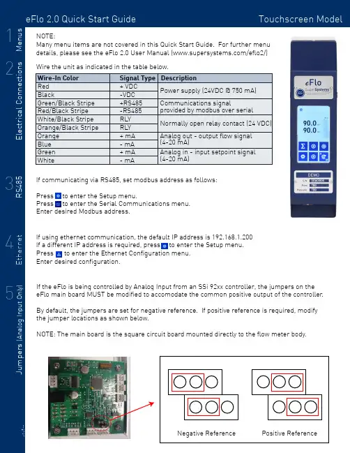
eFlo 2.0 Quick Start Guide Touchscreen Model Signal Type Description + VDC -VDC +RS485-RS485RLY RLY + mA - mA + mA - mA Power supply (24VDC @ 750 mA)Communications signal provided by modbus over serial Normally open relay contact (24 VDC)Analog out - output flow signal (4-20 mA)Analog in - input setpoint signal (4-20 mA)If communicating via RS485, set modbus address as follows:Press to enter the Setup menu. Press to enter the Serial Communications menu.Enter desired Modbus address.Many menu items are not covered in this Quick Start Guide. For further menu details, please see the eFlo 2.0 User Manual (/eflo2/)Positive ReferenceWire the unit as indicated in the table below.Apply gas pressure to the flow meter. Press to enter the Setup menu.Press to enter the Process Variables menu.Hold for two seconds to enter manual mode. Fully close the motor valve by holding the down arrow until the motor drive icon displays .Press to complete the zero tare. Hold to return to auto mode.SSi recommends all flow meters have a zero tare performed for optimal accuracy and control and to equalize the output signal of the differential sensor .If control is unstable or false flow values are indicated when it has been verfied that no gas is passing through the meter, a zero tare may be required.To perform a zero tare:If the meter will be used in Valve mode, a max tare MUST be performed to set the max valve position. To perform a max tare:For additional information, troubleshooting, or other help, see the eFlo 2.0 Quick Reference Guide,the eFlo 2.0 Operations Manual, or contact SSi at 513.772.0060.Apply gas pressure to the flow meter. Press to enter the Setup menu.Press to enter the Process Variables menu.Hold for two seconds to enter manual mode. Hold the Up Arrow until desired max flow is displayed.Press to complete the zero tare. Hold to return to auto mode.Press to enter the Setup menu.Press to enter the Basic Configuration menu.Set altitude to desired level IN FEET.。
Econtrols系统软件使用故障保护策略9、ECI EDIS软件安装及使用方法介绍:软件安装:9.1 软件的安装EDIS——Engine Display Interface Software 发动机显示界面软件双击setup.exe安装点击next(下一步),选择安装路径至安装完成。
9.2 软件的使用(确保ECU接线正确、通讯口线束接线正确、连接诊断线)点击开始菜单栏里面的GCP display 图标,出现下图,将密码复制后,点击paste password,再勾上save password and sn ,点击OK进入软件。
主要页面的介绍(主页面、VEcal页面、CLCalNG页面、Boost页面、Service1和Service2、Test页面、Faults页面、)(1)主页面(介绍包含的一些信息:标定文件版本、燃料控制模式等)2、VEcal页面包含有点火提前角、氧浓度、闭环和自适应修正量(3) CLCalNG页面(4) Boost页面(WGP gate pressure 的调整)在怠速状态下调整WGP gage pressure 压力值至23.5左右(6) Test页面(断缸测试、电子油门和节气门的测试)介绍如何断缸测试(spark kill test),以及测试电子油门和节气门(DBW Test)。
注意:现在标定的点火线圈号和气缸号是一致的,也就是1号线圈对应1缸,5号线圈对应5缸,依次类推(测试在以后会有详细介绍)(7) Faults页面(故障)可以看到当前和历史故障,双击历史故障的红点后出现下图可以清除单个历史故障和所有历史故障代码。
还可以根据出现的故障代码判断出现故障的某个环节。
电压值判断传感器是否完好。
9.4 曲线图的采集一、选择参数进行数据采集:1)、用鼠标右键点击所需要采集曲线的参数,这个参数的方框随即会变为绿色2)、最大允许采集10个参数的曲线,选定完成后单击键盘的P键会出现系统绘制出的曲线图。
edoc2V4.0文档管理系统 免费版安装部署手册1Edoc2V4.0 安装1.1系统必备环境1.2系统必要设置a) IIS中edoc2站点设置注意事项的应用选择2.0版本目录安全性:启用匿名访问b) 给Framework文件夹添加“NETWORK SERVICE“用户的写权限注:如服务器操作系统使用英文版,请进行以下设置后再进行EDOC2安装a) 点击【开始】→【设置】→【控制面板】,选择区域和语言选项b) 选择区域选项,将标准和格式设置为“中文(中国)”,位置设置为“中国”c) 选择高级,将非Unicode程序的语言设置为“中文(中国)”,并将默认用户账户设置勾选上。
1.3安装步骤a) 双击“V4.exe”,运行安装文件b) 进入安装界面,点击“下一步”继续c) 选择接受许可协议,否则无法进入下一步d) 点击“更改…”按钮可以对的安装目录进行自定义,修改完成后按“下一步”继续安装e) 设置数据库连接地址以及数据库登陆用户名和密码注意:SQL必须启用“SQL身份验证”模式,自定义的SQL用户必须享有管理员权限,否则安装步骤的数据库连接步骤将无法通过。
f) 数据库配置:初次安装:选择创建新的数据库,默认为EDoc2V4非初次安装:选择已有数据库。
必须确保使用的数据库与当前安装版本相同g) 完成设置后点击“安装”按钮h) 安装类型如果OS是Server 版本的,您可以选择建立站点或者虚拟目录如果OS是Windows XP Professional 的则只能建立虚拟目录i) 建立好访问路径后,点击“下一步”继续安装创建站点方式创建虚拟目录方式j) 设置文件及文件夹的初始存储位置,点击“下一步”注意:设置的文件存储路径下,必须要有读写的权限,否则会造成系统文件上传或下载失败k) 请再次确认所有的设置是否正确,点击“下一步”按钮进行数据初始化l) 安装成功后会显示访问信息2卸载Edoc2V4.0a) 点击Windows 开始菜单,在所有程序中找到“Macrowing”,选择下面的“卸载”b) 在窗口中选择“除去”选项,然后点击“下一步”进行c) 在弹出窗口中再次进行卸载确认,确认以后系统将会自动卸载d) 卸载完成后,点击“完成”按钮进行确认注意:卸载方式并不会删除数据库和系统中的文档。

服务热线:400-6655-778使用者手册模块化在线式不断电系统深圳雷迪司科技股份有限公司目录1. 安全事项 (1)1.1 重要安全指示 (1)1.2 电磁波防护 (1)1.3 安装信息 (1)1.4 维修 (1)1.5 回收旧电池 (2)2 运作架构 (3)3. 安装 (4)3.1 结构和外观 (4)3.1.1 机柜规格 (5)3.1.2 机柜解说图 (6)3.2 内部构造 (8)3.2.1 输入和输出的断路器 (8)3.2.2 接线端子台 (9)3.2.3 模块 (10)3.3 控制面板和接口 (11)3.3.1 LED 指示灯 (11)3.3.2 液晶显示器 (12)3.3.3 功能键 (12)3.4 安装和接线 (12)3.4.1 安装前的注意事项 (12)3.4.2 安装环境 (12)3.4.3 搬运 (13)3.4.4 拆箱 (14)3.4.4.1 设备包装 (14)3.4.5 定位 (15)3.5 模块 (15)3.5.1 电力模块 (15)3.5.2 安装电力模块 (16)3.5.3 移除电力模块 (17)3.5.4 STS 模块 (17)3.5.5 移除STS 模块 (18)3.5.6 电池安装 (18)3.6 电源电缆 (19)3.6.1 交流输入和输出的最大电流和电力电缆规格 (20)3.6.2 直流最大电流和电力电缆规格 (20)4. 控制面板和显示区域 (21)4.1 简介 (21)4.2 显示内容 (23)4.2.1 起始画面 (23)4.2.2 主画面 (23)4.2.3 选单画面 (24)4.2.4 控制(CONTROL)画面 (24)4.2.5 测量数据(MEASUREMENT)画面 (25)4.2.6 设定(SETUP)画面 (27)4.2.6.1 设定选单之一般子选单(GENERAL) (29)4.2.6.2 设定选单之系统子选单(SYSTEM) (31)4.2.6.3 设定选单之电池子选单 (34)4.2.6.4 预报警画面 (36)4.2.6.5 并机画面 (37)4.2.7 信息画面(INFORMATION) (38)4.2.8 事件(EVENTS)选单画面 (39)4.2.8.1 目前事件 (40)4.2.8.2 历史纪录 (40)4.2.8.3 清除所有事件 (41)4.3 警告清单 (42)5. 接口及通讯 (45)5.1 远程EPO输入埠 (45)5.2 BCB 埠 (46)5.3 维修旁路开关状态埠 (46)5.4 内部输出开关状态埠 (47)5.5 电池柜温度侦测端口 (47)5.6 旁路反馈控制埠 (48)5.7 电池断路器控制埠 (48)5.8 其他通讯接口 (49)6. 维修保养 (50)6.1电力模块、STS控制模块、电池模块的更换步骤 (50)6.1.1 注意事项 (50)6.1.2 电力模块更换步骤 (50)6.1.3 STS控制模块的维修保养步骤 (51)6.1.4 电池模块更换步骤 (51)6.2空气滤网的更换步骤 (52)7.规格 (53)7.1兼容性和标准 (53)7.2环境特性 (53)7.3机柜特性 (54)7.4 电气特性(输入整流器) (54)7.5电气特性(直流电路) (55)7.6电气特性(逆变/变频器输出) (55)7.7电气特性(旁路电源输入) (56)1. 安全事项1.1 重要安全指示此UPS 设备带有致命性的电压,任何相关的维修作业应交由授权的技术人员实施。

ECM-5908通信装置技术和使用说明书版本:V1.01江苏金智科技股份有限公司目录1. 概述 (1)2. 特点 (1)3. 设计规范 (2)4. 主要技术指标 (2)4.1.操作环境 (2)4.2.电气绝缘性能 (2)4.3.机械性能 (2)4.4.电源 (2)4.5.抗干扰性能 (2)4.6.通信接口 (3)4.7.辅助功能 (3)4.8.支持的通信协议 (3)5. 硬件介绍 (4)5.1.硬件模块介绍 (4)5.2.硬件接线说明 (4)5.2.1. 通信接口接线 (4)5.2.2. 跳线设置 (5)6. 软件功能 (6)7. 结构视图及安装尺寸 (7)7.1.装置视图 (7)7.2.安装尺寸 (8)7.3.开孔尺寸 (9)7.4.端子定义 (10)8. 组态软件 (11)9. 调试软件 (11)10. 选型表 (11)1.概述ECM-5908通信装置主要应用于电厂ECS系统、电厂升压站、变电站综自系统等系统,同时适用于石化、钢铁等领域的自动化系统。
作为系统中的通信及规约转换设备,其主要功能是汇总电厂ECS、变电站综自等系统各种保护装置、测控装置及智能设备的数据,并将数据按照一定的要求上送后台系统、DCS或调度;同时接受后台系统、DCS或调度下发的遥控、遥调命令完成对现场各种设备的控制与调节。
ECM-5908通信装置可以提供多种通信接口:以太网(10/100Base-TX、100Base-FX)接口、串行接口(RS-232/485),以及现场总线接口PROFIBUS、CAN接口,同时可以在这些接口上运行多种规约,实现与各种设备的互联。
ECM-5908可以配置成电气完全独立的双机冗余系统,双机之间互作冗余备份。
2.特点●高可靠的嵌入式设计➢ECM-5908采用嵌入式工业网络处理器,主频最高可以达到533MHz,温度范围可以达到(-40℃~+85℃),具有较高的稳定性、可靠性;➢ECM-5908采用了嵌入式实时操作系统和高效率的网络协议,大大提高了通信接口的数据处理流量和速度。


用户手册ADI-2 Pro FS完美转换2通道模拟/ 数字转换器4通道数字/ 模拟转换器AES / ADAT / SPDIF音频接口32 Bit / 768 kHz数字音频USB 2.0类兼容2个超大功率耳机输出数字信号处理高级功能设置ADI-2 Pro FS- v2.0 @ RME 用户手册 11. 简介 (6)2. 包装清单 (6)3. 系统要求 (6)4. 简介及主要特点 (7)5. 首次使用–快速上手 (8)5.1 接口和控制 (8)5.2 快速上手 (9)5.3 设备操作 (9)5.4 菜单结构概览 (10)5.5 播放 (11)5.6 模拟录音 (11)5.7 数字录音 (11)6. 电源供应 (12)7. 固件升级 (12)8. 功能解释 (13)8.1 Extreme Power Headphone Outputs(超大功率耳机输出) (13)8.2 Dual Phones Outputs(双耳机输出) (13)8.3 5-band Parametric EQ (5段参数均衡,PEQ) (14)8.4 Bass / Treble(低音/高音) (15)8.5 Loudness(响度) (15)8.6 SRC(采样率转换) (15)8.7 Crossfeed(交叉串音) (16)8.8 DSP Limitations(DSP限制) (16)基本信息和独立操作模式 (18)9. 操作和使用 (19)10. 前面板控制 (19)10.1 按键 (19)10.2 旋钮 (19)11. VOL(音量) (20)12. I/O(输入/输出) (20)12.1 Analog Input(模拟输入) (20)12.1.1 Settings(设置) (20)12.1.2 Parametric EQ(参数均衡) (21)12.2 Main Output 1/2(主输出1/2) (22)12.2.1 Settings(设置) (22)12.2.2 Bass/Treble(低音/高音) (23)12.2.3 Loudness(响度) (23)12.3 Phones Output 3/4(耳机输出3/4) (24)13. EQ(均衡器) (25)14. SETUP(设置) (27)14.1 Options(选项) (27)14.1.1 Hardware/Diagnosis(硬件/诊断) (27)14.1.2 Clock(时钟) (28)14.1.3 Device Mode(设备模式) (28)14.2 Load/Store all Settings(加载/存储所有设置) (30)15. 电平表界面 (31)15.1 Global Level Meter(全局电平表) (31)15.2 Analyzer(分析仪) (31)15.3 State Overview(状态概览) (32)15.4 Dark Volume(音量黑色主题界面) (33)16. 警示信息 (33)17.1 Auto(自动) (35)17.2 Preamp(前置放大器) (36)17.3 AD/DA Converter(模数/数模转换器) (37)17.4 USB (38)17.5 Digital Through Mode(数字直通模式) (40)17.6 DAC(数模转换器) (41)18. Balanced Phones Mode(平衡耳机模式) (42)19. DSD (43)19.1 综述 (43)19.2 DSD Direct(仅存在于播放过程) (43)19.3 DSD播放 (44)19.4 DSD录音 (44)19.5 DSD电平表 (45)19.6 其他 (45)输入和输出 (46)20. 模拟输入 (47)21. 模拟输出 (47)21.1 综述 (47)21.2 线路输出TS 1/2 (47)21.3 线路输出XLR 1/2 (48)21.4 PH 1/2 (48)21.5 PH 3/4 (49)22. 数字连接 (49)22.1 AES (49)22.2 SPDIF (50)22.3 ADAT (51)安装与操作——Windows (52)23. 驱动安装 (53)24. 设置ADI-2 Pro (54)24.1 Settings(设置)对话框 (54)24.2 时钟模式–同步 (55)25. 操作和使用 (55)25.1 播放 (55)25.2 播放DVD (AC-3/DTS) (55)25.3 多客户端操作 (56)25.4 多设备操作 (56)25.5 ASIO (57)26. DIGICheck Windows (57)安装与操作——Mac OS X (58)27. 综述 (59)27.1 设置ADI-2 Pro (59)27.2 时钟模式–同步 (60)27.3 多设备操作 (60)28. DIGICheck Mac (60)安装与操作——iOS (61)29. 综述 (62)30. iOS下运行的系统要求 (62)31. 设置 (62)32. 支持的输入和输出 (62)技术参考资料 (63)33. 技术指标 (64)33.1 模拟输入 (64)33.2 模拟输出 (64)33.3 数字输入 (65)33.4 数字输出 (65)33.5 数字 (66)33.6 通用 (66)33.7 接口针脚 (67)34. 技术背景 (68)34.1 锁定(Lock)与SyncCheck(同步检查) (68)34.2 延时(Latency)与监听(Monitoring) (68)34.3 Balanced Phones Mode(平衡耳机模式) (69)34.4 Emphasis (71)34.5 高速模式下的噪声电平 (72)34.6 SteadyClock (73)34.7 AD滤波曲线 (75)34.8 DA滤波曲线44.1 kHz (75)34.9 DA脉冲响应 (76)34.10 AD脉冲响应 (77)34.11 频响测量 (78)34.12 响度 (78)34.13 总谐波失真测量 (79)34.14 超大功率 (80)34.15 耳机失真对比 (81)34.16 基于阻抗的电平表PH 1-4 (81)34.17 USB音频 (82)34.18 将ADI-2 Pro作为测量用途的硬件输入/输出 (83)34.19 Hi-Fi环境下的使用 (85)34.20 数字音量控制 (87)34.21 Bit Test(比特测试) (89)其他 (90)35. 配件 (91)36. 产品保证 (91)37. 附录 (92)38. 符合标准声明 (93)用户手册ADI-2 Pro FS概述1. 简介RME ADI-2 Pro在很多方面都可称得上是里程碑式的产品。
EtherCAT® is a registered trademark and patented technology, licensed by Beckhoff Automation GmbH, Germany.Copyright © 2013 by ICP DAS Co., Ltd. All rights are reserved.U ser Manual forSlave Modules ECAT ‐2000 with Digital Inputs andOutputsWarrantyAll products manufactured by ICP DAS are under warranty regarding defective materials for a period of one year, beginning from the date of delivery to the original purchaser.WarningICP DAS assumes no liability for any damage resulting from the use of this product. ICP DAS reserves the right to change this manual at any time without notice. The information furnished by ICP DAS is believed to be accurate and reliable. However, no responsibility is assumed by ICP DAS for its use, nor for any infringements of patents or other rights of third parties resulting from its use.CopyrightCopyright © 2013 by ICP DAS. All rights are reserved.TrademarksNames are used for identification purpose only and may be registered trademarks of their respective companies.Technology SupportIf you have any question for our products, please contact us directly or email to ******************.The shipping package includes the following items:NOTICEIf any of these items is missing or damaged, please contact your local distributor for more information. Keep the shipping materials and overall package in case you want to ship the module back in the future.More⏹ Manual:CD: \fieldbus_cd \ethercat\slave \ecat-2000\manual /pub/cd/fieldbus_cd/ethercat/slave/ecat-2000/manual/ ⏹ ENI:CD: \fieldbus_cd \ethercat \slave \ecat-2000\software/pub/cd/fieldbus_cd/ethercat/slave/ecat-2000/software/ ⏹ FAQ:/root/support/faq/faq.htmlECAT ‐2000 CDQuick StartTable of Contents1 INTRODUCTION (1)2 HARDWARE INFORMATION (2)2.1 ECAT‐2000 G ENERAL T ECHNICAL D ATA (2)2.1.1 E THER CAT I NTERFACE (3)2.1.2 P OWER AND F.G. C ONNECTOR (3)2.1.3 P OWER LED (3)2.1.4 S TATUS LED S (3)2.1.5 I/O S TATUS LED S (3)2.1.6 D IMENSIONS (4)2.2 ECAT‐2045 (5)2.2.1 S PECIFICATIONS (5)2.2.2 I/O C ONNECTOR (P IN A SSIGNMENT) (6)2.2.3 I/O S TATUS LED S (7)2.2.4 W IRE C ONNECTION (7)2.3 ECAT‐2051 (8)2.3.1 S PECIFICATIONS (8)2.3.2 I/O C ONNECTOR (P IN A SSIGNMENT) (9)2.3.3 I/O S TATUS LED S (10)2.3.4 W IRE C ONNECTION (10)2.4 ECAT‐2052 (11)2.4.1 S PECIFICATIONS (11)2.4.2 I/O C ONNECTOR (P IN A SSIGNMENT) (12)2.4.3 I/O S TATUS LED S (13)2.4.4 W IRE C ONNECTION (13)2.5 ECAT‐2052‐NPN (14)2.5.1 S PECIFICATIONS (14)2.5.2 I/O C ONNECTOR (P IN A SSIGNMENT) (15)2.5.3 I/O S TATUS LED S (16)2.5.4 W IRE C ONNECTION (16)2.6 ECAT‐2053 (17)2.6.1 S PECIFICATIONS (17)2.6.2 I/O C ONNECTOR (P IN A SSIGNMENT) (18)2.6.3 I/O S TATUS LED S (19)2.6.4 W IRE C ONNECTION (19)2.7 ECAT‐2055 (20)2.7.1 S PECIFICATIONS (20)2.7.2 I/O C ONNECTOR (P IN A SSIGNMENT) (21)2.7.3 I/O S TATUS LED S (22)2.7.4 W IRE C ONNECTION (22)2.8 ECAT‐2057 (23)2.8.1 S PECIFICATIONS (23)2.8.2 I/O C ONNECTOR (P IN A SSIGNMENT) (24)2.8.3 I/O S TATUS LED S (25)2.8.4 W IRE C ONNECTION (25)2.9 ECAT‐2057‐NPN (26)2.9.1 S PECIFICATIONS (26)2.9.2 I/O C ONNECTOR (P IN A SSIGNMENT) (27)2.9.3 I/O S TATUS LED S (28)2.9.4 W IRE C ONNECTION (28)2.10 ECAT‐2060 (29)2.10.1 S PECIFICATIONS (29)2.10.2 I/O C ONNECTOR (P IN A SSIGNMENT) (30)2.10.3 I/O S TATUS LED S (31)2.10.4 W IRE C ONNECTION (31)3 SOFTWARE COMMUNICATIONS (32)3.1 S TARTUP (32)3.2 C ONFIGURATION (32)A GLOSSARY (37)A.1 O RDERING I NFORMATION (37)A.2 T ECHNICAL S UPPORT (37)The ECAT-2000 series are industrial EtherCAT slave remote I/O modules and equipped with the EtherCAT protocol and installed by daisy chain connection which permits the flexibility in devices installation and reduces infrastructure and operation costs. All the modules can be deployed in the network topologies such as star, line or ring. The isolated input and output design protects the ECAT-2000 against the harmful interference and environment.The ECAT-2000 has passed and verified by the conformance test tool, therefore eligible EtherCAT Master or configurator can manipulate it simply and implement your various applications easily. Fig 1.1 is shown a typical EtherCAT application.F igure 1.1 Typical Application of ECAT-2000.2.1 ECAT ‐2000 General Technical DataF igure 2.1 Appearance of ECAT-200021 Power LED4IN: to Master I/O Status LEDs 6OUT: to Next the EtherCAT Slave EtherCAT Interface I/O Connector 7DIN-Railinstallation3Power and F .G.Connector Status LEDs 52.1.1 EtherCAT InterfaceNotationDescription INEtherCAT data processing, direction to the EtherCAT master OUT EtherCAT data processing, direction to the next slave device 2.1.2 Power and F.G. ConnectorNotationDescription +VsPower Supply with +10~+30VDC GNDPower Supply Ground F.G. Frame Ground; i.e. Earth Contact2.1.3 Power LEDNotationColor States Description PWR RED On The device is powered up 2.1.4 Status LEDsNotation Color StatesDescription OffThe device is in state INIT BlinkingThe device is in state PRE ‐OPERARIONAL Single FlashThe device is in state SAFE ‐OPERARIONAL RUN Green OnThe device is in state OPERARIONAL OffNo link BlinkingLink and activity Link Activity IN/OUT Green On Link without activity2.1.5 I/O Status LEDsNotationColor States Description OffInput voltage is below the lower switching threshold voltage DI Green OnInput voltage is higher than the upper switching threshold voltage OffDigital output status is “Off” DO GreenOn Digital output status is “On”2.1.6DimensionsLeft Side View Front ViewTop ViewRight Side ViewBottom ViewRear ViewUnit: mm2.2 ECAT ‐2045The ECAT-2045 is an industrial EtherCAT slave I/O module which is built in 16 isolated digital outputs. Users can obtain the input and output status not only via the process data but also from its LED indicators.2.2.1 SpecificationsDigital OutputChannels16 Output TypeOpen Collector (Sink) Load Voltage+3.5 ~ +50 V Max. Load Current700mA per Channel Isolation Voltage3750 Vrms PowerInput Voltage Range10V ~ 30VDC Power ConsumptionMax. 4W Communication InterfaceConnector2 x RJ ‐45 ProtocolEtherCAT Distance between StationsMax. 100 m (100BASE ‐TX) Data Transfer MediumEthernet/EtherCAT Cable (Min. CAT 5), Shielded MechanismInstallationDIN ‐Rail Dimensions110mm x 90mm x 33mm (H x W x D, without connectors) Case Material UL 94V ‐0 LevelEnvironmentOperating Temperature ‐25°C ~ 75°CStorage Temperature ‐30°C ~ 80°CRelative Humidity 10 ~ 90%, No CondensationESD (IEC 61000‐4‐2) 4 KV Contact for Each ChannelEFT (IEC 61000‐4‐4) Power: 1 KV Class A; Signal: 1 KV Class A Surge (IEC 61000‐4‐5) 1 KV Class AHi‐Pot 1KV Class A2.2.2I/O Connector (Pin Assignment)2.2.3I/O Status LEDsNotation Color States DescriptionOff Digital output status is “Off”DO GreenOn Digital output status is “On”2.2.4Wire Connection2.3 ECAT ‐2051The ECAT-2051 is an industrial EtherCAT slave I/O module which is built in 16 isolated digital inputs. Users can obtain the input and output status not only via the process data but also from its LED indicators.2.3.1SpecificationsDigital Input Channels 16Input TypeDry (Source) Wet (Sink/Source) Off Voltage Level Open +4V Max. On Voltage Level Close to GND +10 V ~ +50 VIsolation Voltage 3750 VDCPowerInput Voltage Range 10V ~ 30VDC Power Consumption Max. 4WCommunication Interface Connector 2 x RJ ‐45 ProtocolEtherCATDistance between Stations Max. 100 m (100BASE ‐TX)Data Transfer Medium Ethernet/EtherCAT Cable (Min. CAT 5), ShieldedMechanism Installation DIN ‐RailDimensions 110mm x 90mm x 33mm (H x W x D, without connectors) Case MaterialUL 94V ‐0 LevelEnvironmentOperating Temperature ‐25°C ~ 75°CStorage Temperature ‐30°C ~ 80°CRelative Humidity 10 ~ 90%, No CondensationESD (IEC 61000‐4‐2) 4 KV Contact for Each ChannelEFT (IEC 61000‐4‐4) Power: 1 KV Class A; Signal: 1 KV Class A Surge (IEC 61000‐4‐5) 1 KV Class AHi‐Pot 1KV Class A2.3.2I/O Connector (Pin Assignment)2.3.3I/O Status LEDsNotation Color States DescriptionOff Input voltage is lower than +4VDC(Max.)DI GreenOn Input voltage is higher than “Off” state2.3.4Wire Connection2.4 ECAT ‐2052The ECAT-2052 is an industrial EtherCAT industrial slave I/O module built in 8 isolated digital inputs and 8 isolated digital outputs. Users can obtain the input and output status not only via the process data but also from its LED indicators.2.4.1SpecificationsDigital Input Channels 8Input TypeWet (Sink/Source) Off Voltage Level +2V Max. On Voltage Level Close to GND +3.5 V ~ +50 VIsolation Voltage 3750 VDCDigital Output Channels 8Output Type Open Source (Source) Load Voltage +3.5 ~ +50 V Max. Load Current 100mA per Channel Isolation Voltage 3750 VrmsCommunication Interface Connector 2 x RJ ‐45 ProtocolEtherCATDistance between Stations Max. 100 m (100BASE ‐TX)Data Transfer Medium Ethernet/EtherCAT Cable (Min. CAT 5), ShieldedPowerInput Voltage Range 10V ~ 30VDCPower Consumption Max. 4WMechanismInstallation DIN‐RailDimensions 110mm x 90mm x 33mm (H x W x D, without connectors) Case Material UL 94V‐0 LevelEnvironmentOperating Temperature ‐25°C ~ 75°CStorage Temperature ‐30°C ~ 80°CRelative Humidity 10 ~ 90%, No CondensationESD (IEC 61000‐4‐2) 4 KV Contact for Each ChannelEFT (IEC 61000‐4‐4) Power: 1 KV Class A; Signal: 1 KV Class ASurge (IEC 61000‐4‐5) 1 KV Class AHi‐Pot 1KV Class A2.4.2I/O Connector (Pin Assignment)2.4.3I/O Status LEDsNotation Color States DescriptionOff Input voltage is lower than +3.5VDC(Max.)DI GreenOn Input voltage is higher than “Off” stateOff Digital output status is “Off”DO GreenOn Digital output status is “On”2.4.4Wire Connection2.5 ECAT ‐2052‐NPNThe ECAT-2052-NPN is an industrial EtherCAT industrial slave I/O module built in 8 isolated digital inputs and 8 isolated digital outputs. Users can obtain the input and output status not only via the process data but also from its LED indicators.2.5.1SpecificationsDigital Input Channels 8Input TypeWet (Sink/Source) Off Voltage Level +2V Max. On Voltage Level +3.5 V ~ +50 V Isolation Voltage 3750 VDCDigital Output Channels 8Output Type Open Collector Load Voltage +3.5 ~ +50 V Max. Load Current 100mA per Channel Isolation Voltage 3750 VrmsCommunication Interface Connector 2 x RJ ‐45 ProtocolEtherCATDistance between Stations Max. 100 m (100BASE ‐TX)Data Transfer Medium Ethernet/EtherCAT Cable (Min. CAT 5), ShieldedPowerInput Voltage Range 10V ~ 30VDC Power ConsumptionMax. 4WMechanismInstallation DIN‐RailDimensions 110mm x 90mm x 33mm (H x W x D, without connectors) Case Material UL 94V‐0 LevelEnvironmentOperating Temperature ‐25°C ~ 75°CStorage Temperature ‐30°C ~ 80°CRelative Humidity 10 ~ 90%, No CondensationESD (IEC 61000‐4‐2) 4 KV Contact for Each ChannelEFT (IEC 61000‐4‐4) Power: 1 KV Class A; Signal: 1 KV Class ASurge (IEC 61000‐4‐5) 1 KV Class AHi‐Pot 1KV Class A2.5.2I/O Connector (Pin Assignment)2.5.3I/O Status LEDsNotation Color States DescriptionOff Input voltage is lower than +3.5VDC(Max.)DI GreenOn Input voltage is higher than “Off” stateOff Digital output status is “Off”DO GreenOn Digital output status is “On”2.5.4Wire Connection2.6 ECAT ‐2053The ECAT-2053 is an industrial EtherCAT slave I/O module which is built in 16 isolated digital inputs. Users can obtain the input and output status not only via the process data but also from its LED indicators.2.6.1SpecificationsDigital Input Channels 16Input TypeWet (Sink/Source) Off Voltage Level +2V Max. On Voltage Level +3.5V ~ +50 V Isolation Voltage 3750 VDCPowerInput Voltage Range 10V ~ 30VDC Power Consumption Max. 4WCommunication Interface Connector 2 x RJ ‐45 ProtocolEtherCATDistance between Stations Max. 100 m (100BASE ‐TX)Data Transfer Medium Ethernet/EtherCAT Cable (Min. CAT 5), ShieldedMechanism Installation DIN ‐RailDimensions 110mm x 90mm x 33mm (H x W x D, without connectors) Case Material UL 94V ‐0 LevelEnvironmentOperating Temperature ‐25°C ~ 75°CStorage Temperature ‐30°C ~ 80°CRelative Humidity 10 ~ 90%, No CondensationESD (IEC 61000‐4‐2) 4 KV Contact for Each ChannelEFT (IEC 61000‐4‐4) Power: 1 KV Class A; Signal: 1 KV Class A Surge (IEC 61000‐4‐5) 1 KV Class AHi‐Pot 1KV Class A2.6.2I/O Connector (Pin Assignment)2.6.3I/O Status LEDsNotation Color States DescriptionOff Input voltage is lower than +3.5VDC(Max.)DI GreenOn Input voltage is higher than “Off” state2.6.4Wire Connection2.7 ECAT ‐2055The ECAT-2055 is an industrial slave I/O module built in 8 isolated digital inputs and 8 isolated digital outputs. Users can obtain the input and output status not only via the process data but also from its LED indicators.2.7.1 SpecificationsDigital Input Channels 8Input Type Dry (Source) Wet (Sink/Source) Off Voltage Level Open +4V Max. On Voltage Level Close to GND +10 V ~ +50 VIsolation Voltage 3750 VDCDigital Output Channels 8Output Type Open Collector (Sink) Load Voltage +3.5 ~ +50 V Max. Load Current 700mA per Channel Isolation Voltage 3750 Vrms Communication Interface Connector 2 x RJ ‐45 ProtocolEtherCATDistance between Stations Max. 100 m (100BASE ‐TX)Data Transfer MediumEthernet/EtherCAT Cable (Min. CAT 5), ShieldedPowerInput Voltage Range 10V ~ 30VDCPower Consumption Max. 4WMechanismInstallation DIN‐RailDimensions 110mm x 90mm x 33mm (H x W x D, without connectors) Case Material UL 94V‐0 LevelEnvironmentOperating Temperature ‐25°C ~ 75°CStorage Temperature ‐30°C ~ 80°CRelative Humidity 10 ~ 90%, No CondensationESD (IEC 61000‐4‐2) 4 KV Contact for Each ChannelEFT (IEC 61000‐4‐4) Power: 1 KV Class A; Signal: 1 KV Class ASurge (IEC 61000‐4‐5) 1 KV Class AHi‐Pot 1KV Class A2.7.2I/O Connector (Pin Assignment)2.7.3I/O Status LEDsNotation Color States DescriptionOff Input voltage is lower than +4VDC(Max.)DI GreenOn Input voltage is higher than “Off” stateOff Digital output status is “Off”DO GreenOn Digital output status is “On”2.7.4Wire Connection2.8 ECAT ‐2057The ECAT-2057 is an industrial EtherCAT slave I/O module which is built in 16 isolated digital outputs. Users can obtain the input and output status not only via the process data but also from its LED indicators.2.8.1SpecificationsDigital OutputChannels16Output Type Open Source (Source) Load Voltage +3.5 ~ +30 V Max. Load Current 100mA per Channel Isolation Voltage 3750 VrmsPowerInput Voltage Range 10V ~ 30VDC Power Consumption Max. 4WCommunication Interface Connector 2 x RJ ‐45 ProtocolEtherCATDistance between Stations Max. 100 m (100BASE ‐TX)Data Transfer Medium Ethernet/EtherCAT Cable (Min. CAT 5), ShieldedMechanism Installation DIN ‐RailDimensions 110mm x 90mm x 33mm (H x W x D, without connectors) Case MaterialUL 94V ‐0 LevelEnvironmentOperating Temperature ‐25°C ~ 75°CStorage Temperature ‐30°C ~ 80°CRelative Humidity 10 ~ 90%, No CondensationESD (IEC 61000‐4‐2) 4 KV Contact for Each ChannelEFT (IEC 61000‐4‐4) Power: 1 KV Class A; Signal: 1 KV Class A Surge (IEC 61000‐4‐5) 1 KV Class AHi‐Pot 1KV Class A2.8.2I/O Connector (Pin Assignment)2.8.3I/O Status LEDsNotation Color States DescriptionOff Digital output status is “Off”DO GreenOn Digital output status is “On”2.8.4Wire Connection2.9 ECAT ‐2057‐NPNThe ECAT-2057-NPN is an industrial EtherCAT slave I/O module which is built in 16 isolated digital outputs. Users can obtain the input and output status not only via the process data but also from its LED indicators.2.9.1SpecificationsDigital OutputChannels16Output Type Open Collector (Sink) Load Voltage +3.5 ~ +30 V Max. Load Current 100mA per Channel Isolation Voltage 3750 VrmsPowerInput Voltage Range 10V ~ 30VDC Power Consumption Max. 4WCommunication Interface Connector 2 x RJ ‐45 ProtocolEtherCATDistance between Stations Max. 100 m (100BASE ‐TX)Data Transfer Medium Ethernet/EtherCAT Cable (Min. CAT 5), ShieldedMechanism Installation DIN ‐RailDimensions 110mm x 90mm x 33mm (H x W x D, without connectors) Case MaterialUL 94V ‐0 LevelEnvironmentOperating Temperature ‐25°C ~ 75°CStorage Temperature ‐30°C ~ 80°CRelative Humidity 10 ~ 90%, No CondensationESD (IEC 61000‐4‐2) 4 KV Contact for Each ChannelEFT (IEC 61000‐4‐4) Power: 1 KV Class A; Signal: 1 KV Class A Surge (IEC 61000‐4‐5) 1 KV Class AHi‐Pot 1KV Class A2.9.2I/O Connector (Pin Assignment)2.9.3I/O Status LEDsNotation Color States DescriptionOff Digital output status is “Off”DO GreenOn Digital output status is “On”2.9.4Wire Connection2.10 ECAT ‐2060The ECAT-2060 is an industrial slave I/O module built in 6 isolated digital inputs and 6 isolated relay outputs. Users can obtain the input and output status not only via the process data but also from its LED indicators.2.10.1 SpecificationsDigital Input Channels 6Input Type Dry (Source) Wet (Sink/Source) Off Voltage Level Open +4V Max. On Voltage Level Close to GND +10 V ~ +50 VIsolation Voltage 3750 VDCDigital Output Channels 6Output TypeForm A (SPST ‐NO)Contact Rating (Resistive Load) 5A@30VDC; 5A@125/250VAC(47~63Hz) Operate Time 10 ms Max. Release Time 5 ms Max. Mechanical Endurance 2 x 10⁷ Ops. Electrical Endurance 105 Ops. PowerInput Voltage Range 10V ~ 30VDC Power ConsumptionMax. 4WCommunication InterfaceConnector 2 x RJ‐45Protocol EtherCATDistance between Stations Max. 100 m (100BASE‐TX)Data Transfer Medium Ethernet/EtherCAT Cable (Min. CAT 5), Shielded MechanismInstallation DIN‐RailDimensions 110mm x 90mm x 33mm (H x W x D, without connectors) Case Material UL 94V‐0 LevelEnvironmentOperating Temperature ‐25°C ~ 75°CStorage Temperature ‐30°C ~ 80°CRelative Humidity 10 ~ 90%, No CondensationESD (IEC 61000‐4‐2) 4 KV Contact for Each ChannelEFT (IEC 61000‐4‐4) Power: 1 KV Class A; Signal: 1 KV Class ASurge (IEC 61000‐4‐5) 1 KV Class AHi‐Pot 1KV Class A2.10.2 I/O Connector (Pin Assignment)2.10.3 I/O Status LEDsNotation Color States DescriptionOff Input voltage is lower than +4VDC(Max.)DI GreenOn Input voltage is higher than “Off” stateOff Digital output status is “Off”DO GreenOn Digital output status is “On”2.10.4 Wire Connection3 Software Communications3.1StartupEtherCAT devices are described in an XML file, ESI (EtherCAT Slave Information) file, which describes the modules of the ECAT-2000 series named "ICPDAS ECAT‐2000.xml."1.Download the ESI file, ICPDAS ECAT‐2000.xml, from the website/pub/cd/fieldbus_cd/ethercat/slave/ecat-2000/software/ or from the CD in the shipping packageCD: \fieldbus_cd\ethercat\slave\ecat-2000\software2.Copy the file "ICPDAS ECAT‐2000.xml" to the destination folder of EtherCATMaster Tools(Beckhoff EtherCAT Configurator or TwinCAT etc.)C:\EtherCAT Configurator\EtherCAT\ICPDAS ECAT-2000.xmlC:\TwinCAT\Io\EtherCAT\ICPDAS ECAT-2000.xmlOtherwise, if you are using another tool, to the folder set for that tool.3.2ConfigurationThis section is described the configuration using the example of ECAT-2055 and the EtherCAT Configurator supplied by Beckhoff. Otherwise, if another tool is used, choose a configuration method as applicable.1.Start your EtherCAT Configurator.2.Choose File, New to create a new I/O Configuration.3.Click I/O Device with the right mouse button and choose Append Device...in the menu, and then the dialog window Insert Device is opened.4.Select the EtherCAT type in this dialog window and confirm with OK.5.Device 1 (EtherCAT) is added to to your configuration, i.e. a new EtherCATline. Click Device 1(EtherCAT) with the right mouse button and choose Scan Boxes... in the menu.6.Choose the correct network device which is connected to ECAT-2000.7.If the hint is shown, click Yes/OK and continue.8.Click Yes to start scanning for ECAT-2000.9.Click Yes to activate the free run mode for EtherCAT Configurator.10.The ECAT‐2000 (Box 1)is now shown in the EtherCAT Configurator.11.The input and output variables contained in the ESI (*.xml) file of theECAT-2000 are displayed as CANopen Process Data Objects(PDO). The PDOs are listed in the PDO List of the Process Data tab.A GlossaryA.1Ordering InformationEtherCAT Slave DIO ModulesECAT‐2045CR EtherCAT Slave I/O Module with Isolated 16‐ch DO (RoHS)ECAT‐2051 CR EtherCAT Slave I/O Module with Isolated 16‐ch DI (RoHS)ECAT‐2055 CR EtherCAT Slave I/O Module with Isolated 8‐ch DO and 8‐ch DI (RoHS)ECAT‐2060 CR EtherCAT Slave I/O Module with Isolated 6‐ch Relay DO and 6‐ch DI (RoHS)A.2Technical SupportIf you have any difficulties using your ECAT-2000 series modules, please contact us or send a description for the problem to ******************.。
–edoc2内容安全及防扩散模块采用edoc2中国研发中心自主研发的独有技术控制涉密数据流向,任何涉密数据在物理介质上存在如果未经允许,无法私自离开企业内部–与edoc2企业文档管理系统无缝整合–edoc2内容安全及防扩散模块用于进一步保护企业的知识产权、客户资料、财务数据、技术图纸等一切机密信息化数据不外泄。
•简单地说,edoc2防泄密系统使企业机密数据“拷不走”、“屏幕截取不走”、“另存不走”、“打印不走”、“内容复制不走”–edoc2内容安全及防扩散模块的核心是基于虚拟机控制和加密技术–访问控制技术、影子技术、驱动层反截屏技术、剪贴板控制技术、打印控制技术将企业涉密数据完全与外界隔离–对用户的环境进行加密,不影响文件实体本身–DLP Client (标准客户端)–DLP Super Client(超级客户端)DLP Super Client–DLP Server (DLP服务器)–DLP Console (DLP控制台)控制台p–DLP Dispatch Client(外发客户端)DLP支持的系统环境:Windows2000–客户端:Windows 2000、XP、2003、Vista(32&64位)–服务器:Windows 2000、XP、2003、Vista、Linux1.DLP客户端在开机后,登陆机密浏览器区域,用户才可以访问和使用企业的edoc2文件服务器和涉密文件2未装DLP客户端的用户无法访问到企业内部任何涉密应用系统文2.未装DLP客户端的用户无法访问到企业内部任何涉密应用系统、文件服务器、涉密文件。
DLP客户端密人员受控edoc2服务器非涉密客户机DLP客户端DLP客户端–DLP核心控制组件运行于操作系统底层,与企业应用环境的各种应用软件不直接接触,无缝集成,因此与企业已经部署或将要部署的一切应用无关,可以适应企业任何B/S、C/S结构的应用环境的保密需要。
ERP软件edoc2CAD软件财务软件各类操作系统DLP–涉密数据具有新生继承性和接触传播性。
ECO2WIN中文使用手册目录一、简介1.文档说明2.包含部件3.系统配置要求二、软件安装介绍三、软件运行1.通讯连接和设置2.创建一个新项目3.打开一个新项目4.工作窗口介绍四、软件功能框架1.设备状态(DEVICE STATUS)2.电机控制3.电机控制参数设置4.示波器5.子程序编程(SEQUENCER PROGRAMMING)6.设备配置7.参数直接寻址8.系统管理9.数据输出10.数据载入五、控制器调整六、通信协议说明七、附录1、ECOSTEP技术规格和注意事项2、对象词典参数详细注释3、术语表4、应用范例一、简介1、文档说明此文档专为使用KINCO系列伺服系统所设计,在系统开发过程中请一步步按文档要求执行软件功能。
该文档主要描述的是软件ECO2WIN V2.27的功能。
2、包含部件一张带有ECO2WIN的CD;PEAK公司的CAN-DONGLE(并口适配器)或PCAN-USB(USB口适配器);相关的与控制器间的通讯连接线缆3、操作系统和硬件要求奔腾CPU(最少200MHz)内存大于64MBCD-ROM带有232串口、并口或USB接口WIN98/2000/XP二、软件安装介绍当你将ECO2WIN软件光盘放入光驱中,系统将自动运行安装程序,如下图,请选择“ENGLISH‖语言进行安装:注意,所安装的软件除包含有ECOSTEP相关软件,主要包括ECO2WIN和ECOFLASH,其中ECO2WIN是我们必须安装的ECOSTEP驱动器的控制软件,ECOFLASH是用来下载最新的软件RELEASE。
另外,光盘中还有附加的其它软件,如下图,包括ADOBE 阅读器软件和PEAK系列CAN适配器驱动软件,用户可自行决定是否安装。
注意,如果用户选择基于PEAK公司技术的CAN适配器进行控制,则一定要安装相应的驱动软件(包括并口、USB 口等),见下图:重要说明:当软件在WIN98下安装完毕后,需利用厂家提供的ECO2WIN.INI文件对旧文件进行覆盖后方可工作,WIN2000/XP下无此问题。
CAT-2ME误码测试仪使用说明书感谢阁下购买本公司生产的CAT-2ME误码测试仪,在使用之前请详细阅读本使用说明书。
注意本手册任何部分不得复印,翻制或以任何形式在网络中发送,除非得到本公司的书面许可。
本说明书所提及的商标所有权由各商标持有人所有。
本公司有权随时更改产品性能及本说明书而不事先通知客户。
对于以任何形式修改产品及本说明书而造成的产品功能不能实现或对其他产品、人身造成影响,本公司将不负任何责任。
本公司对由合法渠道取得产品的用户提供一年免费质保,但不包括由于操作不当、错误连接和意外而造成的产品损坏及人员伤害。
在质保期内由于产品本身质量而造成不能正常使用的,本公司负责更换,回收的产品由本公司所有。
版本记录:目录注意 (1)一、概述 (3)二、主要功能 (3)三、技术指标 (3)四、前面板功能介绍 (4)五、指示灯 (5)六、操作说明 (6)七、菜单说明 (7)八、使用条件 (13)一、概述CA T-2ME误码测试仪是一款手持式,高性能的,集成幀,无幀测试,中断,在线测试为一体。
具有告警,误码测试、语音监听、M.2100,G.826,G.821分析功能。
同时配有可充电电池,方便维护人员现场使用,它是一款够用、适用、好用、性价比极高的2Mb/S测试仪表,也是人手一机的最佳选择。
二、主要功能1. 在线测试和中断业务测试,且可外接打印机,并将结果进行打印2. 多种伪随机序列可选,用于中断业务成帧或非成帧测试3. 多种固定码可选,方便快速设置成帧方式:PCM31CRC、PCM30CRC,PCM31,PCM30成帧/非成帧测试下的FAS、CRC-4、CORD、E-BIT误码在线测试4. 可人为插入误码,LOS,AIS,LOF等告警插入,且可显示误码数,误码率。
5. 10个超亮LED告警和状态指示,告警,误码声音鸣响指示6. 发送时钟源:内部本振时钟、收信号恢复时钟可选7. ES 、SES、US,按照ITU-TG.821、G.826和M.2100标准进行结果分析8. 带背光高分辨率LCD误码测试、告警测试、性能分析,话路监听等多种功能集中于一体9. 大容量存储功能,可存储多组测试结果,掉电保持,在线话路监听功能,日历,时间显示10. 内置镍氢充电电池,内部集成智能快速充电电路,可在仪表工作的同时完成快速充电11. 手持式结构,适合现场操作三、技术指标比特率:2048Kb/s±50ppm接口:75欧姆,非平衡,高阻输入阻抗>2千欧姆输入灵敏度:0~-43dB线路编码:HDB3帧型:非成帧,成帧组帧:PCM30,PCM30CRC,PCM31,PCM31CRC测试码型:伪随机码:2^23-1,2^15-1,2^11-1,2^9-1固定码:1111,0000,1010告警指示和检测:SIGNAL LOSS,AIS,FRAME LOSS,MF LOSS,PATTERN LOSS,ERROR,REMOTE ALARM,REMOTE MF ALARM误码插入:单误码插入,比特率误码插入: 10E-4,10E-5,10E-6,10E-7结果分析:按照ITU-T的G.821,G.826和M.2100标准差错插入:1比特、10 、10同步:LED指示同步丢失数据格式:同步接口显示:数据接口信号接通显示四、前面板功能介绍仪表面板分为两部分,上部为液晶显示,下部为键盘操作。
CX4-480存储系统硬件和操作概述2008年10月15日本文档介绍具有UltraFlex™技术的CX4-480存储系统的硬件、通电和断电顺序以及状态指示灯。
本章包括以下主题:存储系统主要组件 (2)存储处理器存储模块(SPE) (4)磁盘阵列存储模块(DAE) (9)备用电源(SPS) (15)通电和断电顺序 (16)状态指示灯(LED)和指示器 (21)1存储系统主要组件存储系统包含以下组件:一个存储处理器存储模块(SPE)两个备用电源(SPS)一个光纤通道磁盘阵列存储模块(DAE)(最少具有五个磁盘驱动器)可选DAEDAE有时也称为DAE3P。
存储系统的高可用性功能包括:配置有UltraFlex™I/O模块的冗余存储处理器(SP)备用电源(SPS)冗余电源/冷却模块(称为“电源/冷却模块”)SPE是带有冗余电源和冷却模块的高可用性存储模块。
它的高度为2U(U是NEMA单位;每个单位为4.45厘米),包含两个存储处理器(SP)和电源/冷却模块。
每个存储处理器(SP)使用UltraFlex I/O模块:通过到Windows、VMware和UNIX主机的前端端口实现4Gb/s光纤通道连接和1Gb/s以太网连接。
通过到存储系统磁盘阵列存储模块(DAE)的后端端口实现4Gb/s光纤通道连接。
SP会检测传入主机I/O的速度,并将前端端口的速度设置为检测到的最低速度。
DAE的速度将决定用于连接到SP的后端端口的速度。
表1列出了每个SP支持的光纤通道和iSCSI I/O前端端口以及光纤通道后端端口的数量。
存储系统的光纤通道前端端口和iSCSI前端端口不能是表1中列出的最大数。
每个SP的光纤通道和iSCSI前端端口的实际数量取决于存储系统中UltraFlex I/O模块的数量和类型。
有关详细信息,请参阅UltraFlex I/O模块(第5页)。
2硬件和操作概述表1每个SP的前端端口和后端端口数存储系统光纤通道前端I/O端口数iSCSI前端I/O端口数光纤通道后端磁盘端口数CX4-4804或82、4或64存储系统至少需要使用五个磁盘,并且与一个或多个磁盘阵列存储模块(DAE)配合使用,以便提供TB级的高可用性磁盘存储容量。
台达EtherCAT 分散式从站模块R2-EC0902数位输入继电器输出模块使用手册绵密网络 专业服务中达电通已建立了70余个分支机构及服务网点,并塑建训练有素的专业团队,提供客户最满意的服务,公司技术人员能在2小时内回应您的问题,并在48小时内提供所需服务。
中达电通公司版权所有如有改动,恕不另行通知400 - 820 - 9595地址:上海市浦东新区民夏路238号邮编:201209电话:( 021 )5863-5678传真:( 021 )5863-0003网址: 扫一扫,关注官方微信沈阳电话:(024)2334-1160哈尔滨电话:(0451)5366-5568长春电话:(0431)8892-5060呼和浩特电话:(0471)6297-808北京电话:(010)8225-3225天津电话:(022)2301-5082济南电话:(0531)8690-6277太原电话:(0351)4039-485郑州电话:(0371)6384-2772石家庄电话:(0311)8666-7337上海电话:(021)6301-2827南京电话:(025)8334-6585杭州电话:(0571)8882-0610合肥电话 :(0551)6281-6777武汉电话:(027)8544-8475南昌电话:(0791)8625-5010成都电话:(028)8434-2075长沙电话:(0731)8549-9156重庆电话:(023)8806-0306 昆明电话:(0871)6313-7362广州电话:(020)3879-2175厦门电话:(0592)5313-601南宁电话:(0771)2621-501乌鲁木齐电话:(0991)4678-141兰州电话:(0931)6406-725西安电话:(029)8836-0780贵阳电话:(0851)8690-1374福州电话:(0591)8755-1305序言感谢您使用本产品,本使用手册提供R2-EC0902 EtherCAT远程控制32通道数位输入/32通道继电器输出扩充模块的相关信息。
MONITORING AND CONTROL UNITDoc 242100.11X.DS3 – rev5 Smartpack ControllerMonitoring and Control UnitAdvanced Datasheet – Functions listThis document lists features and functions in a Smartpack based DC power system. Features may be dependent of a specific hardware version, variant and/or optional CAN Node devices.SOLAR CHARGERS • Suppressing solar charger warning during full panel shading (nighttime)• Individual panel shading warningLOAD•Total load current and load fuse monitoring• Total energy consumed logging (se Control System- Energy logging for details) • Individual load current, fuse and power monitoring* – requires Load Monitor device • Individual energy consumed logging* – requires Load Monitor device •Low Voltage Load Disconnect (LVLD)o Adjustable disconnect and reconnect voltages o Timer based disconnect after AC mains fail o Optional AC mains independency •Configurable load descriptionsGENERATOR•Energy supplied logging (se Control System - Energy logging for details)•On/Off control signaling based on SOC monitoring for battery cycling applications, adjustable limits •Time based, daily and/or monthly on/off signaling•Emergency start, “On” signaling (LVBD+1.0V)•Run time monitoring, optional feedback signaling for alarming•Optional delayed system start-up and lowering of charge current limit•Dual generator supportCONTROL SYSTEM•· Multilanguage, changeable “on-the-fly”o English, German, French, Polish, Spanish, Norwegian, Swedish, Finnish, Turkish, Chinese Simplified* and ChineseTraditional* - *Special HWversions•Event loggingo10 000 time stamped records* - HW and SW version dependent•· Data loggingo10 000 time stamped records* - HW and SW version dependento7 user configured monitors, drag-and-drop for any available in control systemo Adjustable time intervals-Normal interval-Critical interval (AC mains failure) •Energy loggingo Resolution from current is 52 times back-Hour [Wh]-Day [kWh]-Week [kWh]•Global settingso Fahrenheit or Celsiuso Site informationo Log on security-Read only level – no password-Service level – 4 digit pin codeo“deciAmpere” option for small systems •Average value and peak value logging of all monitorsINPUTS/OUTPUTS•17 user configurable Alarm Groups for bundling/OR of monitor events•· Boolean AND and NOT of Alarm Groups, 10 Result Groups available•· Alarm relay outputs configurable as Normally Activated or Normally Deactivated•· Clock timer based relay output activation•· Available commands/events trigged by inputs (descriptions changed/customized in setup) o Generic major or minor alarmo Service mode (block alarm relays temporarily)o Generator runningo Lower charge current limito Battery testo Boost/Battery test inhibito Emergency low voltageo Clear manual reset eventsINPUTS/OUTPUTS - OUTDOOR* - REQUIRE O/I UNIT OUTDOOR•· Factory configurable fan speed regulation•· Fan speed deviation alarming•· Humidity Reduction Scheme•· Pressure Test•· Additional Data loggingINPUTS/OUTPUTS - OUTDOOR* - REQUIRE O/I UNIT OUTDOOR•· Web pages access securityo Read only level – user and password protectedo Service level – user and password protectedo Administration level – user and password protected-Same DC power system access level as service, in addition network settings accesso Up to 10 configurable user accounts with own username, access level and passwordo Optional SSL (HTTPS)•SNMPo Supports SNMP v1, v2co Optional heartbeat TRAPo TRAP lap time up to 60 secondso Optional “off TRAPS”o MIB file <ELTEK-DISTRIBUTED-MIB> Branch 9 for 3rd party NMS available-Selection of GET and SET parameters-TRAPs generated by monitor eventso Up to 10 TRAP receive IP addresseso Private or Public communities•DHCP assignation of IP address•Optional email sender with TRAP contentEthernet port with HP Auto MDI/MDI-X for detection and correction for straight-through and crossover cables. Eliminates confusion whether to use straight cable or crossover between controller and PC•Protocols available* - require Smartnode deviceo pComm-Eltek proprietaryo MODBUS (RTU)o PSTN/GSM modem call-back-Simple ASCII data or SMS messaging of Alarm Groupso Telecom Operator specific-TEC-RDP-COMLI-EVTS。