MBRD620中文资料
- 格式:pdf
- 大小:98.48 KB
- 文档页数:4
S
1 2 3
A K F L D G
2 PL
Z U
J H 0.13 (0.005) T
DIM A B C D E F G H J K L R S U V Z
M
CASE 369A–13 ISSUE Y
Motorola reserves the right to make changes without further notice to any products herein. Motorola makes no warranty, representation or guarantee regarding the suitability of its products for any particular purpose, nor does Motorola assume any liability arising out of the application or use of any product or circuit, and specifically disclaims any and all liability, including without limitation consequential or incidental damages. “Typical” parameters which may be provided in Motorola data sheets and/or specifications can and do vary in different applications and actual performance may vary over time. All operating parameters, including “Typicals” must be validated for each customer application by customer’s technical experts. Motorola does not convey any license under its patent rights nor the rights of others. Motorola products are not designed, intended, or authorized for use as components in systems intended for surgical implant into the body, or other applications intended to support or sustain life, or for any other application in which the failure of the Motorola product could create a situation where personal injury or death may occur. Should Buyer purchase or use Motorola products for any such unintended or unauthorized application, Buyer shall indemnify and hold Motorola and its officers, employees, subsidiaries, affiliates, and distributors harmless against all claims, costs, damages, and expenses, and reasonable attorney fees arising out of, directly or indirectly, any claim of personal injury or death associated with such unintended or unauthorized use, even if such claim alleges that Motorola was negligent regarding the design or manufacture of the part. Motorola and are registered trademarks of Motorola, Inc. Motorola, Inc. is an Equal Opportunity/Affirmative Action Employer. Mfax is a trademark of Motorola, Inc. How to reach us: USA / EUROPE / Locations Not Listed: Motorola Literature Distribution; P.O. Box 5405, Denver, Colorado 80217. 303–675–2140 or 1–800–441–2447 Mfax™: RMFAX0@ – TOUCHTONE 602–244–6609 INTERNET: http://Design– JAPAN: Nippon Motorola Ltd.; Tatsumi–SPD–JLDC, 6F Seibu–Butsuryu–Center, 3–14–2 Tatsumi Koto–Ku, Tokyo 135, Japan. 81–3–3521–8315 ASIA/PACIFIC: Motorola Semiconductors H.K. Ltd.; 8B Tai Ping Industrial Park, 51 Ting Kok Road, Tai Po, N.T., Hong Kong. 852–26629298
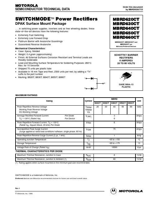
(1) Rating applies when surface mounted on the minimum pad size recommended.
SWITCHMODE is a trademark of Motorola, Inc.
Preferred devices are Motorola recommended choices for future use and best overall value.
2
Rectifier Device Data
元器件交易网
I F(AV) , AVERAGE FORWARD CURRENT (AMPS) 8.0
MBRD620CT MBRD630CT MBRD640CT MBRD650CT MBRD660CT
I F(AV) , AVERAGE FORWARD CURRENT (AMPS) RATED VOLTAGE APPLIED 4.0 TJ = 150°C 3.5 3.0 2.5 2.0 1.5 1.0 0.5 0 0 20 40 60 80 100 120 140 160 TA, AMBIENT TEMPERATURE (°C) VR = 60 V VR = 25 V dc SQUARE WAVE OR SINE WAVE RqJC = 6°C/W TJ = 150°C RqJA = 80°C/W SURFACE MOUNTED ON MIN. PAD SIZE RECOMMENDED
Figure 5. Current Derating, Ambient, Per Leg
1K
C, CAPACITANCE (pF)
100
TJ = 25°C
10 0 10 20 30 40 50 60 70 VR, REVERSE VOLTAGE (VOLTS)
Figure 6. Typical Capacitance, Per Leg
Maximum Instantaneous Forward Voltage (2) iF = 3 Amps, TC = 25°C iF = 3 Amps, TC = 125°C iF = 6 Amps, TC = 25°C iF = 6 Amps, TC = 125°C Maximum Instantaneous Reverse Current (2) (Rated dc Voltage, TC = 25°C) (Rated dc Voltage, TC = 125°C) (2) Pulse Test: Pulse Width = 300 µs, Duty Cycle ≤ 2.0%. VF 0.7 0.65 0.9 0.85 iR 0.1 15 mA Volts
1.0
2.0
3.0
4.0
5.0
6.0
7.0
8.0
9.0
10
IF(AV), AVERAGE FORWARD CURRENT (AMPS)
Figure 1. Typical Forward Voltage, Per Leg
Figure 3. Average Power Dissipation, Per Leg
Rev 1
©RectifierInc. 1996 Data Motorola, Device
1
元器件交易网 MBRD620CT MBRD630CT MBRD640CT MBRD650CT MBRD660CT
ELECTRICAL CHARACTERISTICS PER DIODE
25°C
40 70 20 30 50 60 VR, REVERSE VOLTAGE (VOLTS) *The curves shown are typical for the highest voltage device in the voltage grouping. Typical reverse current for lower voltage selections can be estimated from these curves if VR is sufficient below rated VR.
3 6 6 75 1 –65 to +150 –65 to +175 10000
Amps Amps Amps Amp °C °C V/µs