
Ansys_12.0_CFX_官方教程__4
- 格式:ppt
- 大小:1.83 MB
- 文档页数:38

已验证。
推荐使用。
免费下载。
感谢长河制作。
ANSYS 12.0 安装图文指南作者:长河Blog:Email: fxdx@GTalk:arcsiny@2009-5-11 前言非常令人期待的ANSYS12.0终于在2009年的5月初与我们见面了,经过一天的艰苦下载,我终于有幸得以一睹新版ANSYS的芳容。
相对于以往的版本,ANSYS12.0的变化比较大,而这种变化主要体现在理念的变革。
看来像我这样一贯忽视Workbench的童鞋,应该认认真真地重新学习啦。
或许由于软件的变革,导致安装过程与以往版本有微小差别。
鉴于一些网友对程序安装存在疑问,我索性把自己安装的整个过程抓图总结如下,希望对正准备安装程序的您有些许帮助。
如果您在阅读完本文后,依然存在疑问,欢迎通过我的博客:清溪长河 (记忆方式:十千牛)与我沟通交流。
总体来讲,ANSYS 12.0的安装时间比较长,我计算机的配置为AMD Athlon X2 64、2G内存,依然用了半个多小时。
对于安装程序包,我使用的是2.5G的虚拟光盘文件,安装完毕后,占用硬盘空间超过6G。
希望您在开始正式安装之前,有充足的心理准备,呵呵。
安装过程1、在安装包中找到MAGNiTUDE文件夹2、将该文件夹拷贝到其他位置,比如桌面上。
【注:由于我使用的是虚拟光盘进行安装,存在写入权限的问题,所以才需要将该文件夹拷贝出来。
如果直接使用硬盘文件则无需拷贝】打开文件夹,运行ap120_calc.exe程序。
点击Y,确定,则程序自动生成许可证文件。
3、运行安装主程序,点击setup.exe4、弹出安装菜单,按照从上至下的顺序,先点击第一个按钮,开始安装VC++ 2005 Redistributable、VC++ 2005 SP1 Redistributable、.NET frameword 2.0 SP1。
【从这里貌似可以看出ANSYS在内核方面的改进迹象】5、点击OK6、开始自动安装过程7、安装完毕,重启电脑(可能遇到的问题,没法安装第一步;解决方式,不安装,直接跳过;原因,你的电脑已经安装了比这更高级的编程软件)那也就不必要重启电脑了。
![Ansys_12[1].0_CFX_官方教程__17](https://imgs-1438308264.cos.ap-hongkong.myqcloud.com/0c8d047b31b765ce0508149b.webp)

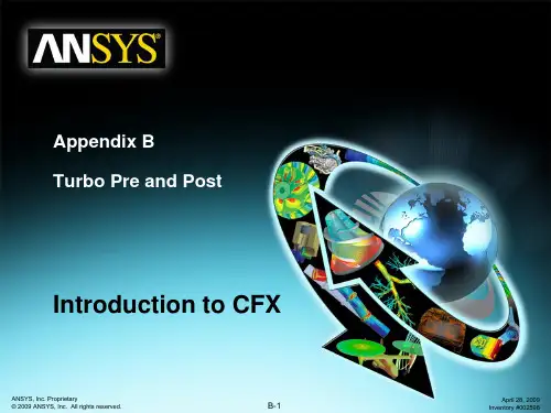
Workshop 2.1ANSYS Mechanical BasicsWorkshop Supplement •The first workshop is extensively documented. As this course progresses, students will become more familiar with basic Workbench Mechanical functionality (menu locations etc.), thus subsequent workshops will contain less details.•Throughout these workshops menu paths are documented as: “First pick > Second pick > etc.”.•Workshops begin with a goals section followed by an assumptions section.Workshop Supplement •Using the Stress Wizard, set up and solvea structural model for stress, deflectionand safety factor.•Problem statement:–The model consists of a Parasolid filerepresenting a control box cover (seefigure). The cover is intended to be used inan external pressure application (1 Mpa/145psi).–The cover is to be made from aluminumalloy.–Our goal is to verify that the part willfunction in its intended environment.Workshop Supplement •We will represent the constrains onthe counter bores, bottom contactarea and inner sides using frictionlesssupports.–Frictionless supports place a normalconstraint on an entire surface.Translational displacement is allowedin all directions except into and out ofthe supported plane. Since we wouldexpect frictional forces to at contactareas this is a conservative approach.Workshop Supplement •Loads: the load consists of a 1 MPa pressure applied to the 17 exterior surfaces of the cover.Workshop Supplement •Open the Project page.•From the “Units” menu verify:–Project units are set to “US Customary (lbm, in, s, F, A, lbf, V).–“Display Values in Project Units” is checked (on).Workshop Supplement1.From the Toolbox choosecreate a Static Structuralsystem (drag/drop or RMB).2.RMB in the Geometry cell andImport Geometry. Browse tothe file “Cap_fillets.x_t”.Workshop Supplement3.Double click the “Model” cell to open theMechanical application.4.When the Mechanical application opens themodel will display in the graphics window andthe Mechanical Application Wizard displayson the right.When Mechanicalstarts if the Wizardis not displayed,use the icon toopen it.Workshop Supplement5.Set the units system:•From the main menu go to “Units > Metric (mm,kg, N, s, mV, mA).Workshop Supplement6.Select a suitable material for the part:a.From the Mechanical Wizard choose “Verify Material”b.Notice the callout box indicates Engineering Data isaccessible from the WB2 interface (Project Schematic).c.Return to the Project schematic window and double click“Engineering Data” to access the material properties.Workshop Supplement7.With General Materialshighlighted click the ‘+’ next to“Aluminum Allow” to add thismaterial to the current project.8.Return to the Project.•Notice the Model cell indicates arefresh is necessary.9.Refresh the Model cell (RMB),then return to the Mechanicalwindow.Workshop Supplement 10.Highlight “Part 1” and click the“Material > Assignment” field tochange the material property toaluminum alloy.Workshop Supplement11.Insert Loads:a.Select “Insert Structural Loads ” from the Wizardb.Follow the call out box to insert a “Pressure ” loadc.The tree will now include a Pressure load in the “Static Structural ”environment branchc.Workshop Supplement12.Apply the load to geometry:a)Highlight one of the outer faces of the part.b)Use the “Extend to Limits” icon to select the remaining 16 faces (total 17 facesselected).c)Click “Apply” to accept the faces.d)Enter a “Magnitude”of 1MPa.a.b.Workshop Supplement 13. Apply supports to constrain the part:a.Select “Insert Supports” from the Wizard.b.Follow the callout box to insert a “Frictionless Support”.c.“Apply”it to the 4 counter bore surfaces of the part.b.Workshop Supplement14.Repeat Steps 13.a. and 13.b. to insert a“Frictionless Support” on the inner surfacesof the bottom recess (use extend to limitsafter selecting one of the inner surfaces.15.Repeat Steps 13.a. and 13.b. to insert a“Frictionless Support” on the lip surface atthe bottom of the recess.Workshop Supplement16.From the Mechanical Wizard request:a)Insert Structural Results (the call out will point to the Solution toolbar).b)Deformation > Total.c)Stress > Equivalent (von-Mises).d)Tools > Stress Tool.Note the Stress Tool detail allows 4 different configurations (explained later). For this workshop we will leave the tool specified as “Max Equivalent Stress ”theory.Workshop Supplement17.Solve the model:a.Select “Solve” from the Wizard.b.Follow the callout box and click on “Solve”.•Note how clicking on “Solve” in the Wizard does not automatically start solving the model but instead, points out the “Solve” icon to the user. Alternatively, you could right click on any branch in the “outline” and choose “Solve”a.b.Workshop Supplement18.View the results:a.Click “View Results ” from the Wizardb.Follow the callout box to where the results are available under the “Solution ”branchb.Workshop Supplement •Plotting a model’s deformation often provides a “reality check” in structural analysis. Verifying the general nature (direction and amount) of deflection can help avoid obvious mistakes in model setup. Animations are often used as well.Workshop Supplement •After reviewing stress results expand the safety tool and plot safety factor. Notice the failure theory selected predicts a minimum safety factor of just over 1.Workshop Supplement 19.Create an html report:a.First choose the graphical items you wishto include in your report by highlighting thebranches and orienting the plot (this is yourchoice).b.Next, insert a “Figure ” from the toolbar.c.Click the “Report Preview ” tab to generatethe report.c.Workshop SupplementNotes on Figures:•Figures are not limited to results items. Adding a plot of the environment branch, for example, will include an image of model boundary conditions in the Report.•Figures are independent. You may set up individual figures and have their orientation, zoom level, etc. retained regardless of the active model orientation or other figures.•Individual branches can have multiple figures associated with them.。