美国QuantumData HDMI视频信号发生器804A样本资料
- 格式:pdf
- 大小:659.07 KB
- 文档页数:2


m8040a 工作电流M8040A是一种高性能的数字通信测试仪器,主要用于测试和模拟各种数字通信接口的工作电流。
它是一款功能强大的设备,可以广泛应用于电信、无线通信、光纤通信等领域。
M8040A的工作电流可以根据需要进行调整,可以同时测试多个工作点的电流。
它采用了先进的数字信号处理技术和高速采样技术,可以准确地测量和分析各种数字通信接口的工作电流。
M8040A的工作电流范围广泛,可以覆盖从几个毫安到几十安的范围。
它支持多种通信接口,包括PCI Express、USB、SATA、Fiber Channel等,可以满足不同应用领域的需求。
M8040A的工作电流测量精度高,能够在微安级别进行测量。
它采用了高精度的测量电路和稳定的电源,可以准确地测量和分析通信接口的工作电流。
同时,M8040A还提供了丰富的数据分析和处理功能,可以对工作电流进行实时监测和分析。
M8040A的工作电流可以通过软件进行设置和控制。
它配备了一套方便易用的软件界面,可以直观地设置和调整工作电流的参数。
用户只需要简单地点击几下鼠标,就可以完成对工作电流的设置和控制。
M8040A除了具备优秀的工作电流性能外,还具备了其他多种优秀的特性。
它拥有高速、稳定的数据传输性能,可以实现高速、高精度的数据采集和处理。
它还具备丰富的测试功能和参数测量功能,可以满足各种不同测试需求。
总之,M8040A是一款功能强大、性能卓越的数字通信测试仪器,以其优秀的工作电流性能在行业内享有很高的声誉。
无论是在电信、无线通信还是光纤通信领域,M8040A都是一款非常理想的测试设备。
它的工作电流范围广泛,精度高,操作简单,具备丰富的测试功能,可以满足各种不同的应用需求。
无论是进行产品研发、产品测试还是生产线测试,M8040A都是一款非常值得信赖的设备。

美国CalSys股份公司HDcctv系列产品技术规格书一、高清数字摄像机HD-SDI是广播级的影像传输技术,一直沿用在电视/电影摄像领域,具有成像清晰,画质无损、几乎零延时的传输特点。
业内将其引入安防领域,就是为了弥补IP摄像机的传输延时、画面有损状况。
采用HD-SDI传输技术的摄像机,是目前最新技术发展的缩影,最大特色是采用了SDI传输技术,有效距离可达110米,且无需对视频信号进行编解码及压缩与解压缩处理,直接传输到显示或存储设备,避免了IP网络传输的延迟及编解码过程造成的画面损坏和丢帧现象,实现了高清图像的无损、无延时传输。
1、高清半球形摄像机(红外、HD-SDI)产品描述:HD-SDI摄像机采用了Panasonic公司1/3英寸200万像素CMOS图像传感器,输出全高清1920*1080@30fps实时视频。
HD-SDI摄像机采用高性能ISP,保证视频清晰细腻、色彩还原真实。
200万像素红外HD-SDI摄像机是一款高清画质,图像无延时无压缩输出、日夜型高性能摄像机,适用于金融、电信、政府、机场、码头、交通监控等要求高清实时画质的场所。
技术参数:2、高清枪式摄像机(CMOS/HD-SDI)产品描述高清枪式摄像机采用了Panasonic公司1/3英寸200万像素CMOS图像传感器,输出全高清1920*1080@30fps 实时视频。
HD-SDI摄像机采用高性能ISP,保证视频清晰细腻、色彩还原真实。
(可选装红外功能)技术参数3、HD-SDI高清数字枪式摄像机(CCD)高清数字摄像机相机,是一款为高端监控量身定制的高清相机。
它除了具有标准监控相机的3A功能(AutoShutter, Auto Gain, Auto IRIS)以外,同时还具有AutoGamma这一独特的功能,配合上相机本身的高灵敏度,高信噪比,高动态范围等一些列的特点,为我们夜间的图像效果及图像亮度提供了良好的保障。
技术参数说明芯片类型逐行扫描 1/1.8英寸彩色 CCD芯片快门类型Global shutter芯片像元尺寸 4.4×4.4umA/D 转换器 14 bit数据接口High Definition Serial Data Interface (HD-SDI)传输速率 1.485Gbit/s视频输出连接器BNC 型连接器,800mVp-p,75-ohm,conforming to SMPTE 292Mserial interface standard视频信号1080P 25帧/30帧;720P 50/60帧数据输出格式YUV 4:2:2GPIO连接器Hirose HR25 8-pin female GPIO connector快门(曝光)自动/手动/one-push, 控制范围(0.02ms – 30ms)范围可调白平衡自动/手动/one-push增益自动/手动/one-push,控制范围(0db – 24db)且范围可调图像预处理Gamma校正,边缘锐化,饱和度,色调照度0.8lux存储器2个存储通道可以存储用户配置的参数摄像机尺寸44mm×29mm×58mm(W×D×H)重量150g 镜头接口方式 C mount 电压需求8-30V最大功率(最大)最大4W,电压为12V 工作温度-10℃- 55℃储藏温度-30℃ - +60℃通风需求自然空气对流保质期1年工作湿度范围20%-90% 抗震10G(20-200Hz)抗冲击70G4、HD-SDI 高清一体化摄像机(CMOS)产品性能:内置索尼最新的高清摄像机模块FCB-CH6300;支持1080P(1920*1080)与720P(1280*720)视频格式输出。


信号发生器使用说明书杭州美控自动化技术有限公司U-S1-MKCN 4第4版杭州美控自动化技术有限公司前言感谢您购买我公司产品。
本手册是关于产品的功能、操作方法和故障处理方法等的说明书。
在操作之前请仔细阅读本手册,正确使用产品。
在您阅读完后,请妥善保管在便于随时取阅的地方,以便操作时参照。
注意本手册内容随仪表的性能及功能提升而改变,恕不提前通知。
本手册内容我们力求正确无误,如果您有任何疑问或发现任何错误,请与我们联系。
版本U-S1-M K CN4第四版2019年6月确认包装内容仪表提供以下标准附件,请确认附件是否齐全并完好无损。
序号物品名称数量备注1信号发生器12测试引线3一红一黑一黄3使用说明书14合格证15USB线16便携包1目录第一章概括 (1)1.1简介 (1)1.2主要功能 (1)1.3技术指标 (2)1.4规格 (3)第二章各部分名称及功能 (4)2.1接线端子 (5)2.2按键 (6)2.3液晶屏显示 (7)第三章信号输出 (8)3.1电压、有源电流输出 (8)3.24-20mA输出 (8)3.3热电偶输出 (9)3.4无源电流输出 (9)3.5电压、电流信号按显示量程输出或测量(免去量程换算) (10)第四章信号测量 (12)4.1电压、有源电流测量 (12)4.2无源电流测量 (13)4.3热电偶测量 (14)4.4调节阀门 (15)第五章可编程输出 (16)5.1分割输出功能(n/m) (16)5.2线性输出功能 (16)5.3自动步进功能 (18)第六章故障排除及仪表维护 (19)6.1故障排除 (19)6.2仪表维护 (20)第一章概括第一章概括1.1简介本信号发生器具有多种信号的测量和输出功能,包括电压、电流、热电偶信号,采用高清LCD液晶屏和功能分明的硅胶按键,显示清晰,操作简单,且具有待机时间长,精度高和可编程输出功能。
广泛应用于实验室、工业现场PLC与过程仪表、电动阀门等的调试。

agilent脉冲信号发生器参数
安捷伦8114A脉冲信号发生器是一款高功率单通道信号源,其主要参数如下:
- 频率范围:1Hz至15MHz。
- 幅度输出:1Vpp至50Vpp(50Ω至50Ω时),2Vpp至100Vpp(1KΩ至50Ω时)。
- 输出电流:20mA至1A(50Ω至50Ω时),40mA至2A(1KΩ至50Ω时)。
- 上升时间:最快可达7ns。
- 定时分辨率:100ps。
- 控制方式:可通过GPIB编程控制,采用SCPI编程命令。
- 保护功能:为保护被测器件,可调节电压、电流和占空比限制。
- 触发方式:可利用外触发或设置门限及人工触发,产生连续脉冲串。
- 人机交互:具有清楚的图形用户界面,自动设置、帮助、存储/调用等功能,易于使用。
这些参数使安捷伦8114A脉冲信号发生器能够生成精确、可重复的脉冲波形,满足各种测试需求。

804激光粒子计数器操作说明MODEL 804 AIR PARTICLE COUNTER804激光粒子计数器可以测量大于等于0.3,0.5,0.7,1.0,2.5,5.0,10微米共7种粒径的微粒,用户可以选择同时测量并显示其中任意4种。
仪器内置的气泵将空气抽入,通过激光散射来计算粒径和粒子数量,计算结果显示在仪器的LCD显示屏上,测量结果可储存在仪器中或输出到PC机。
产品应用: 空气管道检测, 生产过程检测, 检测过滤器性能, 净化室监测, 查找污染源…品牌: MET ONE INSTRUMENTS产地: 美国An Exclusive Supply by Apcee Corporation804仪器出厂初始设置测量通道1(CH1):0.3μm(测量≥0.3微米的粒子)测量通道2(CH2):0.5μm(测量≥0.5微米的粒子) 测量通道3(CH3):5.0μm(测量≥5.0微米的粒子) 测量通道4(CH4):10μm(测量≥10微米的粒子) 常用通道(Favorite)1:0.3μm常用通道(Favorite)2:OFF取样地址(Sample Location):001取样模式(Sample Mode):手动模式(Manual)取样时间(Sample Time):60秒(60 seconds)计数单位(Count Units):立方英尺(CF)一.打开包装有以下物品:804测试仪P/N: 804清零过滤器P/N: 80530数据线P/N: 500784AC-DC变压器及电源线P/N: 80459USB驱动程序P/N: 80328仪器控制程序P/N: 80248保护套P/N: 80450英文操作说明书P/N: 804-9800中文操作说明书P/N: 804-9800C快速说明P/N: 804-9801校正证书P/N: 804-9600手提箱P/N: 8517 警告!该仪器内部装有785nm激光源,该波长是肉眼看不见的。
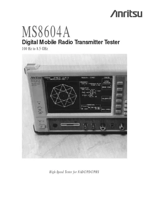
MS8604ADigital Mobile Radio T ransmitter T ester100 Hz to 8.5 GHzHigh-Speed Tester for NADC/PDC/PHSBurst Modulation Accuracy Measured in Under ONE SecondThe MS8604A is a full-featured digital mobile transmitter tester for evaluating the major characteristics of transmitters used in the North-American Digital Cellular Systems (NADC), Japan's digital mobile telephone (PDC: Personal Digital Cellular) system and by cordless telephones (PHS: Personal Handy Phone System). It covers frequencies from 100 Hz to 8.5 GHz, and measures spuri-ous emissions over a broad frequency range. It can also measure RF signals directly up to 10 W (average burst power) and base-band devices can be evaluated using itsI/Q signal input function (option).The MS8604A is ideal for high-speed measurement of frequency deviation, spurious emissions, occupied bandwidth, antenna power, leakage power during carrier-off, transmission ramp-up and ramp-down power, modulation accuracy, leakage power of adjacent channel, and signal trans-mission rate of digital mobile transmitters.In addition to measurements conformingto EIA/TIA, ETSI, RCR, and MKK standards,DSP (digital signal processing) and high-speed measurement function based on a unique measurement algorithm combine to greatly reduce the time required for manu-facturing and inspecting transmitters.PTA functions enabling free programming of test procedures are provided as a standard feature.• Major transmitter functions evaluated by single system• Compatible with NADC/PDC/PHS systems (compatibility with single system provided as standard; optional expansion to all three systems)• High-speed measurement (under 1 second for modulation-accuracy measurements)• Input up to 10 W (internal 20 dB attenuator and power meter for high power levels)• Superior operability• I/Q signal input (option)Fast, Accurate Measurement of Digital Modulated SignalsA unique high-speed measurement method is available for measuring occupied band-width and leakage power of adjacent channel in addition to RCR (Research & Development Center for Radio Systems) standards and Specifications for the type approval test of the Ministry of Posts and T elecommunications of Japan. For RCR standards, a spectrum analyzer is used to determine the occupied bandwidth and leakage power of adjacent channel from the burst signal frequency spectrum.In this method, frequency sweeps must be performed slowly to obtain an accurate burst wave spectrum, so measurement speed falls. For example, more than 10 seconds are required when measuring PDC. With Anritsu's unique measurement method, digital signal processing is used to compute the frequency components from a single burst signal waveform, and the occupied bandwidth and leakage power of adjacent channel are computed from the results. Measurement times of 2 seconds and less are possible for PDC transmitters.Unique High-Speed Measurement Method MS8604AEvaluation of Digital Mobile TransmittersAutomated Measurement by Simple key OperationsQuick Configuration for Different Communication SystemsMeasurement software for one communication system is provided as a standard feature; others can be added as options. When these options are chosen, the communication system can be selected by pressing a single key.Measurement of Frequency, Modulation Accuracy, Signal T ransmission RateBoth absolute frequencies and deviations can be read directly. Measurement of modulation accuracy includes both vector errors within burst signals, amplitude errors,phase errors, origin offset and droop factors, andvector errors for first ten symbols immediately following startup. T en-burst averages and signal transmission rates can also be measured.Measurement of Antenna Power and Leakage Power during Carrier-OffAt measurement of burst signal antenna power, the power-on intervals are auto-detected based on themodulated wave, so an external synchronization trigger is not needed. In addition, the average power during power-on intervals is automatically matched to a tem-plate value, simplifying measurement automation. Any template can be set, and three types can be stored.The leakage power during carrier-off can be measured as either an absolute value or as an on/off ratio.When the carrier-off power is low, measurements can be performed in a wide-dynamic-range mode (duringsingle-mode measurements with synchronizing word).One-T ouch Selection of Measurement ItemsMeasurement items can be selected by pressing a single key . The input connector (RF/IQ), maximum input power ,and type of signal for measurement (uplink/downlink,number of slots per carrier , channel number/frequency , frequency steps, synchronizing words, root Nyquist filter switching) can be preset. In particular , synchronizing words can be predefined to any value. Measurement can be performed in either the single-measurement mode (one measurement performed each time key pressed), or in the automatic continuous repeat mode.Example of burst rise characteristics (PHS)NORMAL modeWIDE DYNAMIC RANGE modeMeasurement of Transmission Ramp-upand Ramp-down PowerTransmission ramp-up and ramp-down power can be measured simultaneously with antenna power measure-ments. In addition, the marker points can be moved and the marker point symbol power can be read directly.Measurement of Leakage Power of Adjacent Channel Users can select either a standard mode usingspectrum-analyzer methods, or a high-speed mode toreduce measurement time.Measurement of Occupied BandwidthUsers can select either a standard mode usingspectrum-analyzer methods, or a high-speed mode toreduce measurement time.Measurement of Spurious EmissionsUp to 15 spurious measurement frequencies can bestored in one memory table and three memory tablesare provided. In addition, a function is provided forautomatic measurement of the highest level withina ±500 kHz range of a specified frequency. By usingspectrum-analysis functions, spurious emissions can bedetected over a wide frequency range.• Measurement TimesNote: Measurement times are for continuous measurement under identical conditions and settings.The modulation error can be found by connecting the I/Q vector components of symbol points.Intervals between symbol points are smoothlyinterpolated for dynamic observation of the movementof I/Q vector components.Constellation Display FunctionThe I/Q vector components of measured signals are displayed as symbol points. The frequency error,RMS/PEAK vector error, and origin offset can also be displayed on the same screen.Scaled Modulation Error DisplayThe modulation error scale can be switched between 5%, 10% and 20%, and can be displayed for each symbol point—a useful feature when making decisions on modulation accuracy.For High-Speed Analysis of Digital Modulated WaveformsConvenient for Real-time Analysis of RF , IF , I/Q Signal Constellation, Evaluation and Adjustment of Modulation CircuitsZone MarkerZone marker reduce measurement time. A marker is automatically set at the signal peak just by setting the received signal in zone marker. Zone marker can be used to set the zone position and width freely.MultimarkerThe multimarker feature displays up to ten markers on the measured waveform, and simultaneously lists the frequencies and levels at the marker points. The multi-marker feature includes harmonic measurement, measurement of the highest ten points, and manual setting function.Harmonic measurement:For measurement of high harmonic spurious emissions; markers are set automat-ically at integer multiples of the carrier frequency,and the frequencies and levels at the marker pointsare displayed.Measurement of highest ten points:Markers are set automatically at the ten points with the highest levels on the screen, and the frequencies and levels at each of the marker points are displayed.Manual setting function:Up to ten markers can be set manually at any frequency.Zone SweepingThe region inside the zone marker is swept repeatedly. For example, if a zone width of 1 division is set,sweeping is 10 times faster than for a full sweep.Full Spectrum Analysis FunctionsThree Measurement ModesIn addition to absolute values in W and dBm, relative values are also displayed in dB.High-Power MeasurementsAntenna power up to 10 W max. (burst average power) can be measured directly using the internal high-power attenuator. This high-power attenuator is pre-calibrated,for accurate measurement of transmitter power levels. Direct Measurement with Broadband Power SensorThe tester has a high-performance power metercomparable to the Anritsu ML4803A. A broadbandamorphous-element power sensor is coupled directly forhigh-precision measurement.USER CAL FACTOR InputWhen losses from connecting cables and externalattenuators are input as the “USER CAL FACTOR,”displayed results are corrected by the factor. And, theburst average power can be displayed by setting aburst wave duty factor for correction.Internal Calibration SignalAn internal 1 mW calibration signal is provided forcalibrating the sensitivity of the power sensorautomatically by pressing the CAL ADJUST key. High-Precision Power-Meter FunctionsPrecise Measurement of Antenna Power by Power-Meter MethodJust pressing the TxT est key produces rapid measure-ment results by category. And spectrum-analyzer functions can be selected with the Spectrum key for signal spectrum analysis.ᕡFunction keys provide one-touch selection of measurement items during transmitter testing.ᕢThese keys select single or repeatedmeasurements.ᕣPress the TxT est key to evaluate transmitters, andthe Spectrum key for spectrum analysis.ᕤFor hard-copying the screen display. In addition,four parameter settings can be saved and recalled.ᕥKeys for entering alphanumeric characters, units and other items.ᕦPMC (Plug-in Memory Card) sloẗThe save/recall function can be used tosave/recall parameter settings to/from the PMC ̈PTA programs can be saved and loaded ̈PMCs can be written and read as data files during PTA program executionᕦIntuitive Key Layout, Simple OperationSeparate Functions for Transmitter Tests and Spectrum AnalysisᕡᕢᕣᕤᕥMS8604AD i g i t a l M o b i l e R a d i o T r a n s m i t t e r T e s t e rPower SensorMeasurement Software and Measurement Items♦Option 11: Measurement Software for PDC (Personal Digital Cellular)♦Option 12: Measurement software for PHS (Personal Handy Phone System)♦Option 13: Measurement software for NADC (North American Digital Cellular Systems): Measurement method for use with MS8604A—: Measurements not included in method for type approval test by the Ministry of Posts and T elecommunications of Japan *1: Method for type approval test by the Ministry of Posts and T elecommunications of Japan*2: Items only for digital systemsMS8604A-Based Automated Measurement Systems The MS8604A includes PTA (Personal T est Automation) programming functions as a standard feature, PTA is a personal computer function that allows the user to simple programs to the function keys for controlling external devices and performing sophisticated measurements. PT A offers outstanding flexibility as a personal specialized automated measurement system.Measurement with one original card Programs written while checking the measurement procedure can be stored in the nonvolatile memory in the MS8604A or saved on the PMC (Plug-in Memory Card). A new card is made every time the user develops a new measurement function, thus making it possible to organize functions by cards.In addition to programs, measurement data and program control variables can also be stored on PMCs.PTA Automated Measurement SystemFull-Featured Interface for Configuring Optimum SystemT wo-Port GP IB SystemThe MS8604A has two GP IB ports as standardequipment. Consequently, a PTA-automated measure-ment system can be expanded to a system controlled by a host. PTA-based distributed processing offers greater efficiency than systems in which several instruments are under the central control of a host.Three-Port InterfaceThe MS8604A is available parallel I/Q interface and an optional RS-232C interface in addition to the two GP IB interface for configuring the ideal PTA-automated measurement system from numerous possible combinations.Parallel I/O Application ExamplesMeasurement itemsAntenna power (spectrum-analyzer method, power-meter method)Frequency deviation (phase-trace method)Occupied bandwidthLeakage power of adjacent channelSpurious emissionsLeakage power during carrier-off Modulation accuracy Signal transmission rate Transmit power control characteristicsI/Q Oscillator Evaluation (using option 03)The modulation accuracy, amplitude and occupiedbandwidth of an I/Q oscillator can be evaluated.Evaluation of Transceiver Characteristics by PTA ControlFrequency Range 100Hz to 8.5 GHz Max. Input Level +40 dBm (10 W)(Continuous wave average power)Frequency: 10 MHzStarting characteristics: ≤5 x 10⁻⁸(option: ≤2 x 10⁻⁸, after 30 min. warm-up) *After 10 min. of warm-up, Reference Oscillator compared to the frequency after 24 hour warm-upAging rate: ≤2 x 10⁻⁸/day(option: ≤5 x 10⁻⁹/day), ≤1 x 10⁻⁷/year (option: ≤5 x 10⁻⁸/year) *Compared to the frequency after 24-hour warm-upT emperature characteristics: 5 x 10⁻⁸(option: 3 x 10-8) *0˚ to 50˚C, relative to the frequency at 25˚C Applicable SystemsNADC (option 13)PDC (option 11)PHS (option 12)Specifications below guaranteed after pressing key for optimizing internal level Frequency range 400 kHz to 2.1 GHz 400 kHz to 2.1 GHz 10 MHz to 2.1 GHz Input level–10 to 40 dBm (burst average power)When using the low power-input connector, measurement to levels 20 dB lower than the above values is possible.Frequency accuracy±(Accuracy of reference oscillator +1 Hz)±(Accuracy of reference oscillator+10 Hz)Modulation accuracy ±(2% of indicated value +0.5%)±(2% of indicated value +0.7%)Origin offset accuracy±0.5 dB to signal level of –30 dBc Transmission rate accuracy ±1 ppmMeasuring range of 48.6 kbps ±100 ppm 42 kbps ±100 ppm384 kbps ±100 ppmtransmission rate Waveform display Constellation display≤1 s (except transmission rate Measurement time ≤1 s (except transmission rate measurement)measurement)≤3 s (transmission rate measurement)≤2 s (transmission rate measurement)Frequency range 10 MHz to 2.1 GHzInput level range +10 to +40 dBm (Average power of burst signal)Transmission power ±10% (using high-power input after calibration with Power Sensor MA4601A)accuracyCarrier-off power Rise/fall edge characteristics Displays rising/falling edges while synchronizing modulation data of measured signal.Measurement time ≤1 s Impedance 50Ω(VSWR: ≤1.2)Frequency range 10 MHz to 2.1 GHz Input level range +10 to +40 dBm (Average power of burst signal)Standard mode (Spectrum analyzer mode)High-speed mode Measurement: Displays results of occupied bandwidth measurement after FFT of measured signalMeasurement time: ≤1 sSpecificationsModulation/Frequency Measure-ment Amplitude Measure-ment Occupied Bandwidth Measure-mentGE N ER A LT R A N S M I T T E RM E AS U R E M E N TMeasurement range in NORMALmode: ≥65 dB (T o average power of burst signal)Average noise level in Wide dynamic range mode: ≤–60 dBm (100MHz ≤Freq. ≤2.1GHZ)*Measurement range is ≥96 dB for +36 dBm input level of average power of burst signalMeasurement:Displays results of occupied bandwidth measurement after measuringsignal with spectrum analyzer Measurement time:Approx. 12 s in full rate when number of data points set to NORMALMeasurement:Displays results of occupied band-width measurement after measuring signal with spectrum analyzer Measurement time:Approx. 4 s when number of data points set to NORMALMeasurement range in NORMALmode: ≥65 dB (T o averagepower of burst signal)Average noise level in Widedynamic range mode:≤–60 dBm(100 MHz ≤Freq. ≤2.1 GHz)*Measurement range is ≥95 dB for3 W input level of average power ofburst signal.Measurement range in NORMAL mode: ≥55 dB (T o average power of burst signal)Average noise level in Wide dynamic range mode:≤–50 dBm (100 MHz ≤Freq. ≤2.1 GHz)*Measurement range is ≥69 dB for 10 mW average power (Burst average power: 80 mW).Applicable SystemsNADC (option 13)PDC (option 11)PHS (option 12)Frequency range 100 MHz to 2.1 GHzInput level range+10 to +40 dBm (Average power of burst signal)MeasurementMeasurement range10 MHz to 8.5 GHz10 MHz to 8.5 GHzFrequency rangeExcept frequency range ±1 MHz of carrier frequency Except frequency range ±50 MHz of carrier frequencyInput level range:+10 to +40 dBm (Average power of burst signal)(Transmission power)≥65 dB (10 MHz to 1.7 GHz)≥60 dB (10 MHz to 1.7 GHz)Measurement range≥75 dB (1.7 to 8.5 GHz)≥70 dB (1.7 to 8.5 GHz)At carrier frequency range 800 MHz to 1.7 GHzAt carrier frequency range 800 MHz to 2.1 GHzInput level range: 0.3 to 1.5 Vp-pI/Q input Input impedance: 5 k Ω, AC/DC coupling (switchable)(option 03)Measurement items:Modulation, Amplitude, Occupied bandwidth Setting range:100 Hz to 8.5 GHz (resolution: 1 Hz), 0 to 2 GHz (freq. band: 0)1.7 to 7.5 GHz (freq. band: 1 –), 6.5 to 8.5 GHz (freq. band 1 +)Preselector range: 1.7 to 8.5 GHz (bands: 1–/1+)Display accuracy: ±(Displayed freq. x Reference freq. accuracy +Span x Span Accuracy)Span:Setting range: 0 Hz, 100 Hz to 8.5 GHzFrequencyAccuracy: ±2.5% (Span ≥1 kHz), ±5% (100 Hz ≤Span < 1 kHz)RBW:Setting range: 10 Hz to 3 MHz (3 dB), 1-3 sequence Accuracy: ±20%Selectivity (60/3 dB), ≤15:1 (100 kHz to 3 MHz), ≤12:1 (10 Hz to 30 kHz)VBW: 1 Hz to 3 MHz, Off, 1-3 sequenceSignal purity (SSB, 1 MHz to 4 GHz): ≤–100 dBc/Hz (10 kHz offset), ≤–115 dBc/Hz (50 kHz offset),≤–120 dBc/Hz (100 kHz offset)Level measuring range: Average noise level to +40 dBmLevel measurementAverage noise level: ≤–112 dBm (10 MHz to 8.5 GHz, RBW 10 Hz, VBW 1 Hz, Input att. setting 20 dB)Residual response: ≤–75 dBm (1 MHz to 8.5 GHz, Input att. setting 20 dB)Setting range: -80 to +40 dBmAccuracy: ±0.5 dB (–30 to +20 dBm), ±0.75 dB (–40 to –30 dBm, +20 to +40 dBm),±1.5 dB (–60 to –40 dBm)After calibration and at Freq. 100 MHz, Span ≤2 MHz, and in Auto mode for Input att, RBW, VBW and Sweep time AmplitudeReference levelsettingsRBW switching error (after calibration): ±0.3 dB (RBW: ≤300 kHz), ±0.7 dB (RBW: ≥1 MHz)LOG/LIN switching error: ±0.3 dB (after calibration)Input attenuator:Setting range: 20 to 75 dB in 5 dB stepsSwitching error: ±0.3 dB (referred to input att. 30 dB, at 100 MHz)Frequency response±0.5 dB (100 MHz to 2 GHz, band: 0), ±1 dB (1.7 to 8.5 GHz, bands: 1–/1+)*Referred to at 100 MHz, Input att. 30 dB, temperature 18˚ to 28˚C (after tuning Preselector at bands 1–/1+)T R A N S M I T T E R M E A S U R E M E N TS P E C T R U MA N A L Y Z ER High speed mode:≥30 dB (30 kHz offset)≥60 dB (60 kHz offset)≥65 dB (90 kHz offset)*Ratio of average power of burstsignal to average value of leakagepower of adjacent channel at burst-on timeStandard mode:≥60 dB (50 kHz offset)≥65 dB (100 kHz offset)High-speed mode:≥60 dB (50 kHz offset)≥65 dB (100 kHz offset)*In High-speed mode, ratio ofaverage power of burst signal to average value of leakage powerof adjacent channel at burst on time Standard mode:≥60 dB (600 kHz offset)≥60 dB (900 kHz offset)High-speed mode:≥60 dB (600 kHz offset)≥65 dB (900 kHz offset)*In High-speed mode, ratio of average power of burst signal to average value of leakage power of adjacent channel at burst on time Spectrum analyzer mode:Displays results of leakage powerof adjacent channel measurementafter measuring signal withspectrum analyzerMeasurement time:Approx. 13 s in full rate whennumber of data points set toNormalHigh-speed mode:Displays results of leakage powerof adjacent channel measuredafter passing signal through internalroot-Nyquist filterMeasurement time: ≤2 sStandard mode:Displays results of leakage power of adjacent channel measurement after measuring signal with spectrum analyzer Measurement time:Approx. 13 s in full rate when number of data points set to Normal in All mode High-speed mode:Displays results of leakage power of adjacent channel measured after passing signal through internal root-Nyquist filter Measurement time: ≤1.5 s Standard mode:Displays results of leakage power of adjacent channel measurement after measuring signal with spectrum analyzer Measurement time:Approx. 5 s when number of data points set to Normal in All mode High-speed mode:Displays results of leakage power of adjacent channel measuredafter passing signal through internal root-Nyquist filterMeasurement time: ≤1.5 sLeakage Power of Adjacent Channel Measure-mentSpurious Measure-mentExternal control PTA NADC (option 13)PDC (option 11)PHS (option 12)LOG:±0.3 (0 to -20 dB, RBW: ≤1 MHz), ±1 dB (0 to –60 dB, RBW: ≤100 kHz),±1.5 dB (0 to -80 dB, RBW: ≤10 kHz)LIN:±5% (to reference level)2nd harmonics:≤–70 dBc (5 to 800 MHz, band: 0, mixer input level: –30 dBm)≤–80 dBc (800 to 850 MHz, band: 0, mixer input level: –30 dBm)≤–90 dBc (850 MHz to 2.1 GHz, bands: 1–/1+, mixer input level: –10 dBm)T wo-single third-order intermodulation distortion:≤–70 dBc (10 to 50 MHz), ≤–85 dBc (50 MHz to 2.1 GHz),*Frequency difference between two signals ≥50 kHz, mixer input level –30 dBmImage response: ≤–70 dBcMultiple-response: ≤–70 dBc (bands: 1–/1+)Sweep time:Setting range:20 ms to 1000 s (TRACE-FREQ., Data points: NORMAL), 50 ms to 1000 s at other conditionsAccuracy: ±10% (20 ms to 200 s), ±15% (200 to 1000 s)Sweep mode: CONTINUOUS, SINGLETrigger: FREE RUN, TRIGGEREDTrigger source: VIDEO, LINE, EXT (±10 V), EXT (TTL)Gate mode (OFF, Random sweep mode):GATE DELAY: 0 to 65.5 ms (in 1 µs steps, GATE END: INT)GATE END: INT/EXTSweep time:50, 100 to 900 µs (Data point: NORMAL, One most significant digit can be set.)1 ms to 1000 s (Data point: NORMAL, two most significant digits can be set.)100, 200 to 800 µs (Data point: DOUBLE, One most significant digit can be set as even number.)1 ms to 1000 s (Data point: DOUBLE, T wo most significant digits can be set as even numberDelay time:Pre-trigger: -time span to 0 s (in 1-point steps)Post trigger: 0 to 65.5 ms (in 1 µs steps)Amplitude display resolution:50 µs to 49 ms, 10 bits (0.1% of full scale)50 ms to 1000 s, 14 bits (0.01% of full scale)POS PEAK, SAMPLE, NEG PEAKNORMAL: 501 points, DOUBLE: 1002 pointsDemodulated waveform display and monitoring demodulated audio signal with internal speakerIF output 21.4 MHz: –10 dBm ±2 dB (at top of screen, with output terminated by 50Ωterminator.)Y output:0 to 0.5 V ±0.1 V (at range between top and bottom of screen, LOG: 10 dB/div., LIN: 10% div.,100 MHz and with output terminated by 75Ωterminator), BNC connectorExternal trigger input:Input 1; Max. ±10 V (in 0.1 V steps, rising/falling edge, selectable and pulse width ≥10 µs), BNC connector Input 2; TTL level (Rising/falling edges, selectable and pulse width ≥10 µs), BNC connector100 kHz to 5.5 GHz–20 to +20 dBm±0.5%±0.5% of full scale at most sensitive range (100 µW range)±0.2% of full scale after zero setting at most sensitive rangeFreq.: 50 MHz, Out: 1.00 mW, Accuracy ±1.2%MA4601A640 x 400-dot, 9-inch ELReference input: 10 MHz ±10 Hz, 2 to 5 Vp-p, ≥50Ω, BNC connectorReference buffer output: 10 MHz, 2 to 3 Vp-p (with the output terminated by a 200Ωterminator), BNC connectorSeparate video output: Compatible with 8-pin DIN connectorOne slot can be connected.Internal memory (4 sets of spectrum and Tx test conditions),Can save/recall setting conditions at external memory (PMC)Can hard-copy screen via GP IB2As device controlled by host, all functions except power switchControl other instruments as controller using PTASH1, AH1, T6, L4, SR1, RL1, PPO, DC1, DT1, CO (C1, C2, C3 and C24 with PTA)Control other instruments as controllerSH1, AH1, T6, L4, SR1, RL1, PPO, DCO, DTO, C1, C2, C3, C4, C28Output port A/B: 8-bit (TTL level), Input/Output port C/D: 4-bit (TTL level), Exclusive port: 3-bit (TTL level)Control signal: 4 (TTL level), +5V output: max. 50mAControl other instruments as controllerPTL: High level language interpreter based on BASICUsing external keyboardOn PMC or FDUpload/Download from/to PC900 Kbytes0˚ to 50˚C85 to 132/170 to 250 Vac, 47.5 to 63 Hz, ≤500 VA221.5 H x 426 W x 451 D mm, < 27 kgEN55011: 1991, Group 1, Class AEN50082-1: 1992Amplitude Linearity(after calibration) Dynamic range SpuriousSweepTime domain waveform displayDetection mode Number of pointsAM/FM demodulation Auxiliary inputs/outputsGP IB 1 (IEEE 488.2) GP IB 2 (IEEE 488.1) I/O portRS-232C (option 02) Language ProgrammingProgram memory Programming capacityS P E C T R U M A N A L Y Z E R P O W E R M E T E RO T H E R S Applicable SystemFrequency rangeLevel range Instrumentation accuracy Zero setZero shift between ranges Calibration oscillator Applicable Power Sensor DisplayInputs/outputs on rear panel External memorySave/recallDirect plottingOperating T emperaturePowerDimensions and massEMC*1*1EMC : Electromagnetic CompatibilityModel/Order RemarksMain frameMS8604ADigital Mobile Radio Transmitter T ester Standard Accessories J0114A Coaxial cord, 1m:1pc.UG-21D/U•RG-9A/U•UG-21D/U J0017F Power cord, 2.5m: 1 pc.P0005PMC:1 pc.BS32F1-C-172, 32 KbytesMA4601A Power Sensor:1 pc.100 kHz to 5.5 GHz, -30 to +20 dBm J0370N Power Sensor Connector Cable, 0.5m 1 pc.F0014Fuse, 6.3A:2pcs.T6.3A250VW0682AE MS8604A Operation Manual:1 pc.OptionsMS8604A-01Reference quartz oscillatorAging rate: ≤5 x 10⁻⁹/dayMS8604A-02RS-232C Interface (for external control)MS8604A-03I/Q inputMS8604A-11Measurement software Ver.3 (PDC)MS8604A-12Measurement software Ver.3 (PHS)MS8604A-13Measurement software Ver.3 (NADC)MS8604A-14Measurement software Ver.2 (Digital MCA)Added to the MS8604A firmware at the factoryMS8604A-15Measurement software Ver.2 (GMSK)MS8604A-16Measurement software (π/4 DQPSK)W0722AE Measurement software operation manual Supplied with Option 14W0876AE Measurement software operation manual Supplied with Option 15W0973AE Measurement software operation manual Supplied with Option 16Z0251AMS8604A service kitApplication softwareSupplied with PMC (Plug-in Memory Card)MX3512A π/4 DQPSK Analysis Software For MS8604A-11/12/13MX3513A Digital MCA Analysis Software For MS8604A-14MX3518A GSM Application Software For MS8604A-15MX3519A DECT Application Software For MS8604A-15MX3520ACT2 Application Software For MS8604A-15Peripheral Equipment and Parts MC3305A JIS type PTA keyboard MC3306A ASCII type PTA keyboard VP-870Printerwith GP-IB (EPSON product)J0007GP IB Cable, 1m 408JE-101J0008GP IB Cable, 2m 408JE-102P0006PMC, 64 KB BS64F1-C-173P0007PMC, 128 KB BS128F1-C-174P0008PMC, 256 KB BS256F1-C-1175P0009PMC, 512 KB BS512F1-C-1176MA4001A Range Calibrator MN1607A 50ΩCoaxial Switch DC to 3 GHz, 50Ω(externally controlled)MP59B 50ΩCoaxial Switch DC to 3 GHz, 50ΩMP640A BranchDC to 1.7 GHz, 40 dB MP654A Directional Coupler 0.8 to 3 GHz, 30 dBMP520C CM Directional Coupler25 to 500 MHz, 50Ω, N type J0395Fixed Attenuator for high-power 30 dB, 30W, DC to 8 GHz J0055Coaxial Adapter NC-P•BNC-J562DC Block10 MHz to 12.4 GHz (NARDA product)B0329D Protective Cover B0331D Front Handle Kit 2 pcs/set B0332Joint Plates 4 pcs/setB0333D Rack Mount Kit B0334DHard Carrying Casewith protective cover castersPlease specify the Model/Order No., names, and quantities when ordering.}Ordering Information。
Quantum Data公司接受Agilent的HDMI 1.3测试方案佚名
【期刊名称】《中国新通信》
【年(卷),期】2007(9)21
【摘要】2007年10月9日,安捷伦科技公司宣布Agilent公司的HDMI 1.3一致性测试方案被Quantum Data公司所认可。
Quantum Data发明了用于识别和帮助解决音视频产品间互操作性问题的测试设备。
【总页数】1页(P19)
【正文语种】中文
【中图分类】TM935
【相关文献】
1.泰克公司HDMI1.3版完整测试解决方案 [J],
2.HDMI^TM一致性测试解决方案(CTS)1.3a版选择泰克仪器作为推荐测试平台 [J],
3.Quantum Data认可安捷伦HDMI 1.3测试方案,其新产品速度将快50%以上 [J],
4.安捷伦科技公司与Quantum Data首次携手开发HDMI自动化解决方案,提供范围最广的视频测试——HDMI一致性测试标准建议使用Quantum Data [J],
5.Agilent HDMI 1.3版一致性测试解决方案率先进军五大授权测试中心 [J],
因版权原因,仅展示原文概要,查看原文内容请购买。
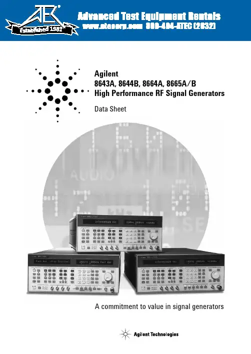
Agilent8643A, 8644B, 8664A, 8665A/BHigh Performance RF Signal GeneratorsData SheetA commitment to value in signal generators1981Agilent’s high performance RF signal generators – choose one for……Best price to performance•252 kHz to 1030 MHz, 2060 MHz Option 002•For out-of-channel tests•Electronic attenuator for high use•Lowest cost of the "family"•AM, FM, pulse modulation•Built-in 2 GHz counter (Option 011)•VOR/ILS signal simulation (Option 009)•Ultra low leakage (Option 010)…Best spectral purity•252 kHz to 1030 MHz, 2060 MHz Option 002•Lowest SSB phase noise and spurious•Highest output power•Lowest residual FM•AM, FM, pulse modulation•Built-in 2 GHz counter (Option 011)•VOR/ILS signal simulation (Option 009)•Ultra low leakage (Option 010)…High RF frequency coverage•100 kHz to 3000 MHz - 8664A, 4200 MHz - 8665A, 6000 MHz - 8665B•Low SSB phase noise (Option 004)•AM and wideband FM•High performance pulse modulation (Option 008)•Ultra low leakage (Option 010)1.For FM receivers with approximately 14 kHz IF BW and 25 kHz channel spacing3Performance backed by Agilent’s reputation and manufacturing experience4Typical performance, for applications that push specificationsSSB phase noiseSSB phase noise is an important specifica-tion of a signal generator if it is to be used for measuring the adjacent channel selec-tivity of a receiver. If the phase noise of the signal generator is too high at frequency offsets equal to the channel spacing, the test results might indicate a failure of the receiver when it is actually functioning properly. For a receiver with <90 dB of selectivity the 8643A is recommended. If the selectivity is ≥90 dB, the 8644B (or 8664A with Option 004, or 8665A/B Option 004) is recommended.Output level accuracyOutput level accuracy is a combination of temperature variation, flatness over fre-quency, and the signal generator’s internal attenuator and detector accuracies. The graph represents worst case output level accuracy of a sampling of 8665Bs. All of these units fall within the shaded area. RF leakageDue to radios becoming more sensitive and operating at higher frequencies, the traditional two-turn loop measurement of RF leakage has become inadequate. To overcome the shortcomings of the two-turn loop, Agilent has developed a new measurement technique using resonant dipole antennas, which is 20-25 dB more sensitive than the two-turn loop method. Agilent has been able to reduce the level of radiated emissions in its newer signal generators through innovative design and packaging. Understanding that not all applications require the lowest possible emissions, Option 010 is available on all of these performance signal generators.Typical SSB phase noise and spurs at 1 GHZ8664A 8665A/BstandardOption 004-60-80-100-120-140-16010 100 1K 10K 100K 1M 10MSSBphasenoise(dBc/Hz)(f) [dBc/Hz] vs. f[Hz]Typical SSB phase noise and spurs at 1 GHZ8643A8644B-60-80-100-120-140-16010 100 1K 10K 100K 1M 10M 40MSSBphasenoise(dBc/Hz)(f) [dBc/Hz] vs. f[Hz]5Internal modulation source •Low distortion sinewaves to 400 kHz with variable phase and amplitude.•Triangle, sawtooth and squarewaves to 50 kHz with variable phase and amplitude.•White Gaussian noise with variable amplitude.•Two independent sources for two-tone testing.Optional pulse modulation(Option 008, 8664A and8665A/B)•An Agilent designed GaAs pulsemodulator provides the exceptionalperformance that is so critical for pulsedapplications.•<5 ns rise/fall times, >80 dB on/offratio.•Built-in pulse generator featuresinclude variable pulse delay and widthfrom 50 ns to 999 ms. This savespurchasing additional equipment.•Leveled RF output maintains accuracywhile in pulse modulation.High reliability electronicattenuator on the 8643A(optional on 8644B)For applications up to 1 GHz, the electronicattenuator used in the 8643A providesincreased reliability. Instead of usingmechanical relays, the electronic attenuatoruses solid-state components for settingoutput levels accurate to within ±1.0 dB.The Agilent patented design uses PINswitching elements with three millionhours of MTBF, giving the attenuator anestimated 0.2% failure rate.Features that improve the usability of Agilent’s 8643A, 8644B, 8664Aand 8665A/B for your application!6Wideband FM (8664A and 8665A/B)•Typical rates to 5 MHz with 2 MHz of deviation, or rates to 800 kHz with10 MHz of deviation (f c>1500 MHz) allows testing of most wideband receivers.•Excellent FM linearity is inherent due to YIG oscillator design.•Stable dc-coupled FM for measurements that require low carrier drift.Performance signal generatorseries features•High stability oven controlled timebaseis standard.•Surface mount construction forimproved reliability.•Three year calibration cycle (MTBC)means less time in the calibration lab.•Built-in self-diagnostics and calibrationsaves valuable time by significantlyreducing down time.2 GHz frequency counter(Option 011, 8643A and 8644B)•20 Hz to 2 GHz frequency counting viafront panel connector.•Cost and space efficient solution forapplications involving audio frequencymeasurements, local oscillator, IF andtransmitter testing.•Eliminates the need to externally couplethe timebase references when using anexternal counter.7Specifications1.3000 MHz for 8664A, 4200 MHz for 8665A, 6000 MHz for 8665B. 8Specifications (continued)1.3000 MHz for 8664A, 4200 MHz for 8665A, 6000 MHz for 8665B.2.One watt on 8665B.3.Low noise mode three.9Specifications (continued)10Specifications (continued)11Agilent Technologies’ Test and Measurement Support, Services, and AssistanceAgilent Technologies aims to maximize the value you receive, while minimizing your risk and problems. We strive to ensure that you get the test and measurement capabilities you paid for and obtain the support you need. Our exten-sive support resources and services can help you choose the right Agilent products for your applications and apply them successfully. Every instrument and system we sell has a global warranty. Support is available for at least five years beyond the production life of the product. Two concepts underlie Agilent’s overall support policy: “Our Promise” and “Your Advantage.”Our PromiseOur Promise means your Agilent test and meas-urement equipment will meet its advertised performance and functionality. When you are choosing new equipment, we will help you with product information, including realistic perform-ance specifications and practical recommenda-tions from experienced test engineers. When you use Agilent equipment, we can verify that itworks properly, help with product operation,and provide basic measurement assistance forthe use of specified capabilities, at no extra costupon request. Many self-help tools are available.Your AdvantageYour Advantage means that Agilent offers awide range of additional expert test and meas-urement services, which you can purchaseaccording to your unique technical and busi-ness needs. Solve problems efficiently and gaina competitive edge by contracting with us forcalibration, extra-cost upgrades, out-of-warran-ty repairs, and on-site education and training,as well as design, system integration, projectmanagement, and other professional engineer-ing services. Experienced Agilent engineers andtechnicians worldwide can help you maximizeyour productivity, optimize the return on invest-ment of your Agilent instruments and systems,and obtain dependable measurement accuracyfor the life of those products.For more assistance with your test andmeasurement needs go to:/find/assistOr contact the test and measurement expertsat Agilent Technologies(During normal business hours)United States:(tel)180****4844Canada:(tel)187****4414(fax) (905) 206 4120Europe:(tel) (31 20) 547 2000Japan:(tel) (81) 426 56 7832(fax) (81) 426 56 7840Latin America:(tel) (305) 267 4245(fax) (305) 267 4286Australia:(tel) 1 800 629 485(fax) (61 3) 9272 0749New Zealand:(tel) 0 800 738 378(fax) 64 4 495 8950Asia Pacific:(tel) (852) 3197 7777(fax) (852) 2506 9284Product specifications and descriptions in thisdocument subject to change without notice.Copyright © 2001 Agilent TechnologiesPrinted in the USA, April 30, 20015091-2580E12。
This product supports 4K 60Hz 4:4:4 subsampling for HDR televisions. To ensure optimal performance, check the factory default settings on your TV:Frequency (Hz) should be set to 60HzqHDR feature should be enabledqHDMI input settings should be set to 2.0qUHD Deep Color should be set to ONqHDMI over Cat6 Extender Kit,Transmitter/Receiver, PoC, HDR, 4K @ 60 Hz,4:4:4, Up to 125 ft., TAAMODEL NUMBER:B127-1A1-HHTransmitter/receiver kit extends a 4K x 2K HDMI audio/video signal via Cat6 cable to a projector, monitor or HDTV up to 125 ft. away.FeaturesHDMI Extender Ideal for Digital Signage or Displaying Video in Schools or Trade Show Booths This complete transmitter and receiver system is recommended for video presentations in conference rooms, schools, trade shows, meeting facilities, houses of worship, retail settings and digital signage applications where the source and display are farther apart than conventional A/V cables allow. The B127-1A1-HH extends 4K video and stereo audio signals from an HDMI source device to an HDMI display up to 125 feet (38.1 meters) away via user-supplied Cat6 cabling.Transmits Crystal-Clear 4K HDMI Video with Multi-Channel Audio and 4:4:4 ColorThe B127-1A1-HH supports Ultra HD video resolutions up to 3840 x 2160 (4K x 2K) at 60 Hz with full, rich uncompressed DTS-HD, Dolby TrueHD and 7.1-channel digital audio. Built-in equalization automatically fine-tunes the image quality at the remote display with no time-consuming manual fiddling needed. It’s compatible with HDCP 2.2, EDID and HDMI 2.0 standards for carrying HDR (high dynamic range) signals. It also supports 4:4:4 chroma subsampling for top-level PC gaming or using your HDTV as a PC monitor.Built-In PoC Technology Provides Receiver Power to Avoid Bulky External Power BricksBuilt-in Power over Cable (PoC) technology powers the low-profile receiver over Cat6 cable. Green and orange LEDs on both the transmitter and receiver will light up to indicate the system is receiving power and a signal is being transmitted.Plug-and-Play Operation for Quick Setup and Immediate UseThe included transmitter and receiver units work right out of the box with no software required. Mounting hardware is included for installing the units on walls, poles or 19-inch racks. Connect the transmitter to the source and the receiver to the display with user-supplied HDMI cables (such as Tripp Lite’s P568- or HighlightsDelivers UHD picture quality atresolutions up to 3840 x 2160(4K x 2K) @ 60 HzqPower over Cable (PoC)technology provides power tothe receiver via Cat6 cableqTransmitter’s local HDMI portallows you to see the Ultra HDimage being displayedqCompatible with latest HDMIstandards, including 4:4:4subsampling for HDR televisions qPlug-and-play operation with nosoftware required for easy,immediate installationqApplicationsConnect a media server, Blu-ray player, cable/satellite box, Roku, gaming system or other hometheater component to a large-screen 4K television or projector qUpgrade the video quality ofyour trade show presentation ordigital signage installation in acommercial or educationalsetting to 4K x 2KqSystem RequirementsSource device with HDMI output (Blu-ray player, cable box,laptop)qDisplay device with HDMI input(HDTV, projector, monitor)qPackage IncludesTransmitter unitqReceiver unitqSpecificationsP569-Series). Then, connect the two units using Cat6 patch cable (such as Tripp Lite N202-Series cable).Connect an optional display to the transmitter’s local HDMI output to monitor the image connected to the receiver up to 125 feet away.TAA-Compliant for GSA Schedule PurchasesThe B127-1A1-HH is compliant with the Federal Trade Agreements Act (TAA), which makes it eligible for GSA (General Services Administration) Schedule and other federal procurement contracts.External power supply (Input:100–240V)q(4) International plug adapters (North America, Europe, U.K.and Australia)qMounting hardware qOwner’s manualq© 2020 Tripp Lite. All rights reserved. All product and company names are trademarks or registered trademarks of their respective holders. Use of them does not imply any affiliation with or endorsement by them. Tripp Lite has a policy of continuous improvement. Specifications are subject to change without notice. Tripp Lite uses primary and third-party agencies to test its products for compliance with standards. See a list of Tripp Lite's testing agencies:https:///products/product-certification-agencies。
Agilent 81110A Agilent 81100 Family ofPulse Pattern GeneratorsData Sheet – Version 1.3Flexible Pulses or Patterns for DigitalDesigns – Key Features• Pattern mode on all models from 80 MHz to 660 MHz,including pseudo-random binary sequence• The outputs of dual-channel instruments can be added(analog or EXOR, depending on model)• User-retrofittable channels for most models• Upward compatibility• Individual solutions for frequencies up to 50, 80, 165, 330, 400 and 660 MHz• 100% form/fit compatibilitySignals for testing digital designs and componentsThe Agilent 81101A, 81104A, 81110A and 81130A generate all the standard pulses and digital patterns needed to test current logic technologies (CMOS, TTL, LVDS, ECL, etc.).With the optional second channel on all of the models from 80 MHz to 660 MHz, multi-level and multi-timing signals can be obtained using the internal channel addition feature.• Variable pulse parameters in pattern mode as well as in pulse mode (not on the 81130A)• Synchronously triggerable• Simulation of reflections/distortions• (81104A, 81110A)• Three/four-level codes (81104A, 81110A)Glitch-free timing changesTiming values can now be swept without the danger of misleading pulses ordropouts that could cause measurement errors. (Applies to continuous mode, values < 100 ms, consecutive values between 0.5 and twice the previous value on the 81101A, 81104A, 81110A).Reliable measurementsAll models provide clean, accurate pulses with excellent repeatability, thus contribut-ing to measurement integrity.The Agilent 81110A features self-calibration for more accuracy. It also offers a choice of output modules. The Agilent 81111A 165 MHz 10 V module with variable transitions.Along with the Agilent 81112A 330 MHz 3.8 V module, which has differential out-puts and two selectable transition times.The Agilent 81130A offers a choice of output modules: the Agilent 81131A 400 MHz, 3.8 V module and the Agilent 81132A 660 MHz, 2.5 V module which has complementary outputs.Easy-to-useFeatures such as the clear graphicaldisplay, autoset, help, store/recall, preset TTL/ECL levels, selectable units (such as current/voltage, width/duty-cycle), and load compensation ensure a high level of convenience.Stimulate the device’s environmentToday’s devices can require very complex stimuli. To meet this, the Agilent 81130A can sequence and loop its memory for very deep patterns. RZ (return-to-zero), NRZ (non-return-to- zero) and R1 (return-to-one) formats are available. Digital channel addition allows the generation of signals with two different pulse widths and delays or of data rates up to 1.32 Gbit/s in one single channel.Frequency rangeThe Agilent 81130A is designed and recommended for an operation in the frequency range of 170 kHz to 400/660 MHz. However it can be operated in the extended range down to 1 kHz.Data Sheet 81100 Family of Pulse Pattern Generators21. Depends on selected impedance (all other values for 50 Ω source impedance into 50 Ω load).2. 0.001% +15 ps with internal PLL as clock source.3. Also avalable as VXI pulse pattern generators E8311A and E8312A.Agilent 81100 - Family of Pulse Pattern Generators81101A SpecificationsBurst Count : 2 to 65536 (single or double pulses).Delay : Delay, phase or % of period.Double pulse delay : Double pulse and delay are mutually exclusive.Duty cycle : Set between 0.1% and 95% (subject to width limits. 99.9% with overprogramming).Transition times: These can be entered as leading/trailing edge or % of width. Leading and trailing edges are indepen-dent within one of the following over-lapping segments (1:20 ratio):• 5 ns - 20 ns • 10 ns - 200 ns • 100 ns - 2 µs • 1µs - 20 µs • 10 µs - 200 µs • 100 µs - 2 ms • 1 ms - 20 ms •10 ms - 200 msData Sheet 81100 Family of Pulse Pattern Generators3Repeatability : Is typically four times better than accuracyOutput timing fidelity : Period, delay and width are continuously variable without any output glitches or dropouts.Data Sheet 81100 Family of Pulse Pattern GeneratorsTrigger modesContinuous : Continuous pulses, double pulses or bursts (single or double pulses).External triggered : Each active inputtransition (rising, falling or both) generates a single or double pulse or burst.External gated : The active input level (high or low) enables pulses, double pulses or bursts. The last single/double pulse or burst is always completed.External width : The pulse shape can be recovered whilst the period and width of an external input signal are maintained. Levels and transitions can be set.Manual : Simulates an external input signal.Internal triggered : Internal PLL replaces an external trigger source.Inputs and outputsClock input/PLL reference and external input: One input (BNC connector at rear panel) is used for clock input or alterna-tively for the PLL.PLL reference : The internal PLL is locked to an external 5 MHz or 10 MHz reference frequency.Clock input : The output period isdetermined by the signal at CLK input. Ext. input : Used for trigger, gate or external width.Level parameters: Can be entered as volt-age or current, as high and low level, or as offset and amplitude.Load compensation:The actual load value can be entered (for loads ≠ 50 Ω) to display actual output values. On/off: Relays connect/disconnect output (HiZ).Normal/complement: Selectable.Limit : Programmable high and low levels can be limited to protect the device-under-test.Input impedance : 50 Ω/10 kΩ selectable.Threshold : -10 V to +10 V.Max. input voltage : ±15 Vpp.Sensitivity : 300 mVpp typical.Input transitions : < 100 ns.Frequency : Dc to 50 MHz.Minimum pulse width : 10 nsStrobe output and trigger output trigger format : One pulse per period with 50% duty cycle typical.External mode : 9 ns typ.Level : TTL or ECL selectable.Output impedance : 50 Ω typical.Max. external voltage : -2 V/+7 V.Transition times : 1.0 ns typical for TTL, 600 ps typical for ECL.41. In ±19 V level window81104A and 81110A SpecificationsBurst count: 2 to 65536 (single or double pulses).Delay : Delay, phase or % of period.Double pulse and delay : Mutually exclusive.Duty cycle : Set between 0.1% and 95% (subject to width limits. 99.9% with over-programming).Repeatability : Is typ. four times better than accuracy.Transition times : leading/ trailing edge or % of width. Leading and trailing edges are independent Agilent 81111A/Agilent 81105A) within one of the following overlapping segments (1:20 ratio): • 2 ns (3 ns) - 20 ns • 10 ns - 200 ns • 100 ns - 2 ms • 1µs - 20 µs • 10 µs - 200 µs • 100 µs - 2 ms • 1 ms - 20 ms •10 ms - 200 msOutput timing fidelity : Period, delay and width are continuously variable without any output glitches or dropouts.Overprogramming : All parameters of the Agilent 81110A, except transitions, can be set to whatever the 330 MHz timing system will allow. This applies also when the Agilent 81111A (165 MHz) output module is used.Data Sheet 81100 Family of Pulse Pattern Generators51. Source impedance is selectable from 50 Ω to 1 KΩ for the Agilent 81111A.2. Changing of amplitude may add 0.5 ns.Level/Pulse Performance CharacteristicsLevel parameters: voltage or current, high or low level, offset or amplitude.On/off: relays connect/ disconnect output (HiZ).Load compensation: the actual load value can be entered (forloads ≠ 50 Ω) to display actual output values. (Applies to theAgilent 81105A and Agilent 81111A only).Normal/complement: selectable.Limit: programmable high and low levels can be limited to protect the device-under-test.Channel Addition (with Agilent 81105A or Agilent 81111A output channels)If the instrument is equipped with 2 output modules, channel 2 can be added to channel 1 internally. In this case the second output is disabled. The additional fixed delay on the second channel is typ. 2.5 ns. The following parameters differ from the above specifications if two output modules (Agilent 81105A/Agilent 81111A) are added.Data Sheet 81100 Family of Pulse Pattern Generators61. In ± 19 V level window.Pattern modePattern length: 16 kbit/channel and strobe output.Output format: RZ (return to zero), NRZ (non-return to zero), DNRZ (delayednon-return to zero).Random pattern:PRBS 2 ^ (n - 1) n = 7,8, (14)Trigger modesContinuous: Continuous pulses, double pulses, bursts (single or double pulses)or patterns.External triggered: Each active input transition (rising, falling or both) generates a single or double pulse,burst or pattern.External gated: The active input level (high or low) enables pulses, double pulses, bursts or patterns. The last single/double pulse, burst or patternis always completed.External width: The pulse shape can be recovered. Period and width of an external input signal is maintained. Delay, levels and transitions can be set.Manual: Simulates an external input signal.Internal triggered: Internal PLL replaces an external trigger source. Pulses, double pulses, bursts or patterns can be set.Strobe output and trigger outputStrobe output: User-defined, 16 kbitpattern (NRZ) when in pattern mode.Trigger format: One pulse per period with50% duty cycle typical. External mode:1.5 ns typ. for Agilent 81110A. 5.9 ns typ.for Agilent 81104A.Level: TTL or ECL selectable.Output impedance: 50 Ω typical.Max. external voltage: - 2 V/+7 V.Transition times: 1.0 ns typical for TTL,600 ps typical for ECL.Inputs and OutputsClock input/PLL reference andexternal inputPLL reference: (BNC connector at rearpanel). The internal PLL is locked to anexternal 5 MHz or 10 MHz referencefrequency.Clock input: (BNC connector at rearpanel). The output period is determinedby the signal at CLK input.Ext. input: Used for trigger, gate orexternal width.Input impedance: 50 Ω/10 kΩ selectable.Threshold: - 10 V to + 10 V.Max. input voltage: ± 15 Vpp.Sensitivity: ≤ 300 mVpp typical.Transitions: < 100 ns.Frequency: dc to max. frequencyof output module.Min. pulse width: 1.5 ns (as width ofoutput module in external width mode).711. Subtract 4 ns from the typ. delay value when referring to OUTPUT 1 / 2 for the Agilent 81112A output module and add 1 ns when referring toOUTPUT 1 / 2 for the Agilent 81104A with the Agilent 81105A output module.Data Sheet 81100 Family of Pulse Pattern GeneratorsData Sheet 81100 Family of Pulse Pattern Generators8Burst count : 2 to 65504.Delay : Delay, phase or % of period.Duty cycle : Set between 0.1% and 99,9% (subject to width limits).Repeatability : Is typ. four times better than accuracy.1. The uncertainty of 1 period can be eliminated if an external clock and the following setup and hold times are upheld. setup time: 0.3 ns to 4.3 ns; hold time: -2.8 ns to 4.0 ns.Data Sheet 81100 Family of Pulse Pattern GeneratorsSequencing : A sequence is a succession of segments. One outer loop running once or continuous, and one nested loop can be applied. The nested loop can be set from 1 to 2 ^ 20 repetitions.Segment : The memory can be divided into maximal 4 segments.Segment length resolution : This is the resolution for which the segment can be set dependent on the maximum data rate. See Table 1.Limit : Programmable high and low levels can be limited to protect the device-under-test.Segment types: Pattern, PRBS, high and low segments ( “0” or “1” levels segments selectable).Note : If one channel is set to PRBS the other channel can only be high or low segments, or PRBS type.Random pattern : PRBS 2 ^ n - 1,n = 7,8,...,15 (CCITT 0.151).Level parameters : Voltage or current, high and low level, or offset and amplitude.Pattern and sequencingPattern length: 65504 bit/channel. If PRBS is used: (65503-RBLength).Pattern formats : NRZ (non-return-to-zero), DNRZ (delayed non-return-to-zero), RZ (return-to-zero) and R1 (return-to-one) can be selected (see Figure 1).On/off : Relays connect/disconnect output (HiZ).9Segment length resolution trade-offs1. The minimum length in the first segment of a nestedloop is two times that of the segment length resolution.Width is a multiple of clock periods.Width and delay can be set as required.Width and delay can be set as required.The signal can be delayed as required.Output pattern formats Non-return-to-zeroR1RZ DNRZNRZReturn-to-oneReturn-to-zero Delayed non-return-to-zeroData Sheet 81100 Family of Pulse Pattern GeneratorsTrigger modesContinuous : Continuous pulses, bursts or patterns.External started : Each active input transi-tion (rising, falling edge) generates pulses, bursts or patterns.External gated : The active input level (high or low) enables pulses, bursts or patterns. On an external gate signal the output is immediately stopped, that means the last cycle will not be completed.Manual : Simulates an external input signal with push of a front panel button.Inputs and outputsClock input/PLL reference and external inputConnectors : SMA (f) 3.5 mm Input impedance : 50 ΩTermination voltage : -2.10 V to 3.30 V Input sensitivity : < 400 mV typ.Max. input voltage : -3 V to + 6 V Input transitions : < 20 nsOnly valid for clock input/PLL reference One input is used for clock input or for the PLL reference alternatively.Reference : The internal PLL is locked to the 1,2,5 or 10 MHz. The output frequency of the instrument must be larger than the clock input/PLL reference frequency.External clock : The output period is determined by the signal at clock input. Clock input frequency : 170 kHz to 660 MHz (at 50% ±10% duty cycle).Delay from input trigger output : 21 ns.Delay from input to output : 53 ns.Threshold : ac coupled. Only valid for external input.External input : Used for external started or gated.Input frequency : DC to 330MHz.Delay from external input to trigger output : 22ns + 0 to 1 period.Delay from external input to output : 54 ns + 0 to 1 period.Threshold : -1.4 V to +3.7 V.Trigger outputTrigger format : One pulse per period with 50% duty cycle typical. In pattern mode the trigger pulse can be set to mark the start of any segment.Output impedance : 50 Ω typical.Level : TTL/ETTL (for frequency < 180 MHz), 1 V to GND, ECL 50 Ω to GND/-2 V, PECL 50 Ω to + 3 V.Max. external voltage : -2 V/+3 V.Transition times : 1.0 ns typical for TTL, 600 ps typical for ECL.Delay from external input to trigger output : 32 ns typical.Channel 1 +Figure 2: Channel addition10Programming times: (measured at display off)1. Range depends on segment length resolution, see previous table.Data Sheet 81100 Family of Pulse Pattern Generators11Ordering Information - 81100 FamilyThe minimum configuration for a working instrument consists of a mainframe and one output module. The second output module can be added later. Output modules can be exchanged and retrofitted by the user. The Reference Guide (811xx-91021) is supplied with each mainframe for all configurations. A memory card is not included.Each Agilent 81101A mainframe includes one output channel (in comparison to the other models of the Agilent 81100 family). The output module of the 81101A does not need to be ordered separately.Agilent 81101A50 MHz one channel pulse generator, 10 V Quick start guide language options Opt OBI Engish Guide(811xx-91021)Opt ABF French Guide(81101-91210)Opt ABJ Japanese Guide(81101-91510)Opt AB0Taiwan Chinese Guide(81101-91610)Opt AB1Korean Guide(81101-91710)Opt AB2Chinese Guide(81101-91810)Additional documentation optionsOpt 0BW Service Manual(81101-91021)Agilent 81104A80 MHz pulse/pattern generatormainframeOutput module:Agilent 81105A 80 MHz, 10 VAgilent 81110A330/165 MHz pulse/pattern generatormainframeOutput modules:Agilent 81111A 165 MHz, 10 VAgilent 81112A 330 MHz, 3.8 VNote: Only use output modules of thesame module number. A combination ofthe Agilent 81111A and Agilent 81112A inone Agilent 81110A is not possible.Quick start guide language optionsOpt OBI Engish Guide(811xx-91021)Opt ABF French Guide(81110-91210)Opt ABJ Japanese Guide(81110-91510)Opt AB0 Taiwan Chinese Guide(81110-91610)Opt AB1Korean Guide(81110-91710)Opt AB2 Chinese Guide(81110-91810)Additional documentation optionsOpt 0BW Service Manual(81110-91021)Agilent 81130A400/660 MHz pulse/data generatormainframeOutput modules:Agilent 81131A 400 MHz, 3.8 VAgilent 81132A 660 MHz, 2.4 VNote: Only use output modules of thesame module number. A combination ofthe Agilent 81131A and Agilent 81132A inone Agilent 81130A is not possible.Quick start guide language optionsOpt OBI Engish Guide(811xx-91021)Opt ABF French Guide(81130-91220)Opt ABJ Japanese Guide(81130-91520)Opt AB0Taiwan Chinese Guide(81130-91620)Opt AB1Korean Guide(81130-91720)Opt AB2Chinese Guide(81130-91820)Additional documentation optionsOpt 0BW Service Manual(81130-91021)Opt 0B1English Quick StartGuide (includes EnglishRef eremceGuide)Opt ABJ Japanese Quick StartGuide (includes EnglishRef erecnceGuide)Opt 0B0 Does not include anyQuick Start Guide(includes EnglishReferenceGuide)All options are orderable with themainframes.AccessoriesOpt UN2Rear panel connectors (insteadof front panel)Opt 1CP Rack mount and handle kit(5063-9219)Opt 1CN Handle kit (5063-9226)Opt 1CM Rack mount kit (5063-9212)Opt 1CR Rack slide kit (1494-0059)Opt UFJ 1 MB SRAM memory card(0950-3380)Opt UK6Commercial cal. certificate withtestdataData Sheet 81100 Family of Pulse Pattern Generators 12Product specifications and descriptions in this document subject to change without notice.© Agilent Technologies, Inc. 2009Printed in USA, November 24, 20095980-1215E。
视频信号发生器操作手册视频信号发生器详情请联系深圳君辉电子郑经理:138****5356K-826X 简易操作手册(不同型号会有些差异)1视频信号发生器操作手册2前言感谢您购买MIK可编程视频信号发生器。
本操作手册为您提供操作方法,让您可以高效使用本设备进行高清电视,投影机,显示器等的开发、生产及检测等。
产品输出信号类型及应用手册< K -8267R 前面板>< K -8267R 后面板>3■ 交流电源-. 断开电源线时,首先关闭信号发生器前部电源开关,然后拔掉电源线。
-. 确保电源线未损坏。
-. 开关电源请使用前面板ON/OFF 开关。
■ 无外部干扰-. 清除液体、易燃物和金属 (磁铁等)。
-. 移开风扇周围物体。
■ 禁止垂直安装-. 请在平滑地方安装信号发生器,切勿垂直安装。
■ 无振动-. 信号发生器为高频高精度设备,强烈振动可能引发故障。
■ 显示器设备与K-826X 连接前-. K-826x 与显示器设备连接时需保持断电。
-. 为避免潜在异常情况及电击,请将两设备间进行屏蔽接地。
-.接地线至■ 当K-826X 与显示器设备断开连接时 -. 关闭电源,断开连接。
-. 断开信号线,然后屏蔽接地线。
■ 前部 C/F Card 的操作-. 关闭电源,然后插入或断开连接。
-. 若电源未关闭时插入或断开连接,则可能造成Flash Card 损坏及数据丢失。
■ 系统稳定之时间设定-. 可以打开电源立即开始设定时间,但建议待5分钟后具体数据稳定后再行设定。
视频信号发生器操作手册1.一般规格1.1 K-826X 系统概要K-826X可编程视频信号发生器是以用户为中心,使其编辑图形操作简单化,输出信号多样化;给予PDP,LCD TV Monitor, TFT-LCD Monitor, HDTV等生产厂家的研发和生产提供视频信号检测的设备,输出信号支持Analog, DVI, HDMI, CVBS,Y/C, YPbPr, D-Terminal, Scart。
H D M I接口硬件测试标准及说明(总69页)--本页仅作为文档封面,使用时请直接删除即可----内页可以根据需求调整合适字体及大小--HDMI接口硬件测试2017-11-09目录 Table of Contents1综述 .............................................................................................................. 错误!未定义书签。
2HDMI的应用优势.......................................................................................... 错误!未定义书签。
音视频融合 ........................................................................................................... 错误!未定义书签。
良好的兼容性 ....................................................................................................... 错误!未定义书签。
出色的抗衰减能力 ............................................................................................... 错误!未定义书签。
支持更多原色色深 ............................................................................................... 错误!未定义书签。
D i s c l a im er : T h i s d o c u m e n t a t i o n i s n o t i n t e n d e d a s a s u b s t i t u t e f o r a n d i s n o t t o b e u s e d f o r d e t e r m i n i n g s u i t a b i l i t y o r r e l i a b i l i t y o f t h e s e p r o d u c t s f o r s p e c i f i c u s e r a p p l i c a t i o n sProduct data sheetCharacteristics140DDO35300discrete output module Modicon Quantum - 32 O solid stateMainRange of productModicon Quantum automation platform Product or component type Dc discrete output module Discrete output number32ComplementaryGroup of channels 4 groups of 8Discrete output logic Positive logic (source)Addressing requirement 2 output words Discrete output voltage 24 V DC Output voltage limits 19.2...30 VAbsolute maximum output 56 V for 1.3 s decaying pulse Voltage drop0.4 V 0.5 A Maximum load current16 A per module 16 A per module 4 A per group 4 A per group Surge current <= 5 A for 0.0005 s Response time <= 1 ms at state 0 to state 1<= 1 ms at state 1 to state 0Leakage current 0.4 mA 30 VLoad inductance Inductance(H) = 0.5/((current(A))² x (switching frequency(Hz))) 50 Hz Fault indication Blown fuseLoss of field power Associated fuse rating3 A each point 3 A each point 5 A per group 5 A per groupIsolation between channels and bus 1780 Vrms DC for 1 minute Isolation between group 500 Vrms DC for 1 minuteProtection typeInternal output protection by 5 A fuse per groupPower dissipation 1.75 W + (0.4 V x total module load current)Marking CELocal signalling1 LED green bus communication is present (Active)1 LED red external fault detected (F)32 LEDs green input status Bus current requirement 330 mA 330 mA Module format Standard Product weight0.45 kgEnvironmentProduct certificationsABS BV C-Tick DNVFM Class 1 Division 2GL GOST RINA RMRSSafety certification non interfering StandardsCSA C22.2 No 142UL 508Resistance to electrostatic discharge 4 kV contact conforming to IEC 801-28 kV on air conforming to IEC 801-2Resistance to electromagnetic fields 10 V/m 80...2000 MHz conforming to IEC 801-3Ambient air temperature for operation 0...60 °C Ambient air temperature for storage -40...85 °CRelative humidity 95 % without condensation Operating altitude<= 5000 mOffer SustainabilitySustainable offer status Green Premium productRoHS (date code: YYWW)Compliant - since 0848 - Schneider Electric declaration of conformity Schneider Electric declaration of conformity REAChReference not containing SVHC above the threshold Reference not containing SVHC above the threshold Product environmental profileAvailableProduct environmental Product end of life instructionsAvailableEnd of life manualContractual warrantyWarranty period18 monthsDimensions DrawingsRacks for Modules MountingDimensions of Modules and Racks(1) 2 slots (2) 3 slots (3) 4 slots (4) 6 slots (5)10 slots (6)16 slotsConnections and Schema24 Vdc Discrete Output Source Module Wiring Diagram。
© Meggitt SA / 262-710 / Version 12 / 08.11.2017 / E 1 / 16Information contained in this document may be subject to Export Control Regulations of the European Union, USA or other countries. Each recipient of this document is responsible for ensuring that transfer or use of any information contained in this document complies with all relevant Export ControlRegulations. ECN N/A.IPC704Signal conditionerFEATURES»From the Vibro-Meter ® product line »For CAxxx piezoelectric accelerometers and CPxxx dynamic pressure sensors »Configurable high-pass and low-pass filters »Frequency range: 0.5 Hz to 20 kHz»Optional integrator to produce a velocity output »Optional 2-wire current or 3-wire voltage transmission»Certified for use in potentially explosive atmospheres»A range of installation options are availableIPC704IECEx NEPSI KGSDESCRIPTIONThe IPC704 signal conditioner converts the charge-based signal from a piezoelectric-based transducer into a current or a voltage signal. This current or volt-age signal is transmitted to the processing electronics via a standard 2-wire or 3-wire transmission cable. The current modulation technique allows transmis-sion over a distance of up to 1 km. A GSI galvanic separation unit is required for this configuration.The electronic circuitry of the IPC704 signal condi-tioner is incorporated into a moulded aluminium enclosure. The signal conditioner has configurablehigh-pass and low-pass filters and an optional inte-grator to give a velocity output. Furthermore, RFI fil-ters protect the input and output against radio-frequency interference and other electromagnetic influences.A range of installation options are available for the IPC704 signal conditioner, including:» A polyester enclosure providing environmental protection against dust, oil and water jets.»A mounting adaptor allowing the IPC704 signal conditioner to be mounted on a DIN rail.Signal conditioner IPC7042 / 16© Meggitt SA / 262-710 / Version 12 / 08.11.2017 / EDESCRIPTION (continued)Two versions of the IPC704 signal conditioner are available:»An IPC704 for sensors using standard piezoelectric materials, for example, CAxxx,CP10x and CP2xx(ordering number 244-704-000-042-... ).»An IPC704 for sensors using GaPO4 piezoelectric material, for example, CP50x (ordering number 244-704-000-511-... ).BLOCK DIAGRAM(electrically c onductive)COM O/P +24VSPECIFICATIONSEnvironmental characteristics(Specifications according to IEC 60068-2 recommendations)GeneralTemperature•Operation:−30 to +85 °C•Storage:−40 to +85 °CHumidity:Max. 95 % non-condensing.Note: For operation in a humid environment, ordering option A3 (pottedversion) should be considered.Protection rating(according to IEC 60529):IP40Vibration(according to IEC 60068-2-26):2 g peak between 10 and 500 HzShock acceleration(according to IEC 60068-2-27):15 g peak (half sine, 11 ms duration)Industrial housing (ordering option G1)Protection rating(according to IEC 60529):IP66Impact resistance:> 4mJ/mm2 (DIN 53453)Chemical resistance:Good resistance to seawater, acids, alkaline solutions, gasoline and oils Flammability:UL94V-0 self-extinguishing© Meggitt SA / 262-710 / Version 12 / 08.11.2017 / E3 / 16Signal conditionerIPC704Explosive atmospheresAvailable in Ex approved versions for use in hazardous locationsType of protection Ex i: intrinsic safety (ordering option A2)EuropeEC type examination certificate LCIE 02 ATEX 6085 XII 2G (Zones 1, 2)Ex ib IIC T6 … T4 GbNorth AmericaC CSAUS certificate C CSA US 1243981Class I, Division 1, Groups A, B, C, DEx ia (T6 to T4)International IECEx certificate of conformity IECEx LCI 06.0009XEx ib IIC T6 … T4 GbChina NEPSI certificate of conformity*GYJ12.1450XEx ib IIC T6 to T4 GbKoreaKGS certificate of conformity 12-GA4BO-0396XEx ib IIC T6 to T4Type of protection Ex nA: non-sparking (ordering option A3)EuropeVoluntary type examination certificate LCIE 09 ATEX 1027 XII 3G (Zone 2)Ex nA IIC T6 … T5 GcNorth AmericaC CSA US certificate C CSA US 1243981Class I, Division 2, Groups A, B, C, D Ex nA IIC T6 to T5 Gc Class I, Zone 2AEx nA IIC T6 to T5 GcInternationalIECEx certificate of conformity IECEx LCIE 13.0053XEx nA IIC T6 … T5 Gc* N ot engraved on the product marking.For specific parameters of the mode of protection concerned and special conditions for safe use, refer to the certificates that are available from Meggitt SA on demand.When using protection mode ‘nA’ (non-sparking apparatus), the user shall ensure that the signalconditioner is installed in an enclosure that ensures a protection rating of at least IP54 (or equivalent).For the most recent information on the Ex certifications that are applicable to this product, refer to the Ex product register (PL-1511) document that is available from Meggitt SA.Industrial housing (ordering option G1)Available in Ex approved versions for use in hazardous locations•Environment:II 2 G (Zones 1, 2) Ex e II < 109Ω (DIN 53482)•Surface resistivity for Ex version:Stuffing glandsAvailable in Ex approved versions for use in hazardous locations•Environment:II 2 G/D (Zones 1, 2) Ex e II For specific parameters of the mode of protection concerned and special conditions for safe use,refer to the certificates that are available from Meggitt SA on demand.For the most recent information on the Ex certifications that are applicable to this product, refer to the Ex product register (PL-1511) document that is available from Meggitt SA.SPECIFICATIONS (continued)Signal conditioner IPC7044 / 16© Meggitt SA / 262-710 / Version 12 / 08.11.2017 / EPower supply to IPC704Voltage :18 to 30 V DC Current:25 mA (max.)Transfer characteristics (ordering option B)IPC704 for sensors using standard piezoelectric materials (244-704-000-042-... )•Transfer without integrator:0.1 to 10 mV/pC or 0.1 to 10 µA/pC •Transfer with integrator:981 to 98 100 mV/(pC.s) or 981 to 98 100 µA/(pC.s)IPC704 for sensors using GaPO 4 piezoelectric material (244-704-000-511-... )•Transfer:0.1 to 50 mV/pC or 0.1 to 50 µA/pC Linearity error:≤ 0.2 %Temperature stability :100 ppm / °C typicalPhase:180° between the input signal and the acceleration output.180° between the input signal and the pressure output. 90° between the acceleration and velocity outputs.See the graph below.Input characteristics (ordering option C)Compatible sensors:Any piezoelectric-based transducer – symmetrical or non-symmetrical, case grounded or insulated Dynamic range:100 000 pC peak Input sensitivity•Accelerometers:See IPC704 for accelerometers (acceleration output) using standard piezoelectric materials on page 6 andIPC704 for accelerometers (velocity output) using standard piezoelectric materials on page 6•Dynamic pressure transducers:See IPC704 for pressure sensors using standard piezoelectric materials on page 7 andIPC704 for pressure sensors using GaPO4 piezoelectric material on page 8Charge amplifier:Symmetrical RFI filter:Symmetrical LC network Resistance:≥ 50 k Ω (sensor and cable)Capacitance:≤ 10 nF (sensor and cable)SPECIFICATIONS(continued)Input signalAcceleration and pressureVelocity At© Meggitt SA / 262-710 / Version 12 / 08.11.2017 / E 5 / 16Signal conditionerIPC704Output characteristics (ordering option D)RFI filter:Symmetrical LC network 2-wire current transmission•Dynamic signal:Max. ± 5 mA peak •Standing current :12 mA ± 0.5 mA•Electrical connection:+24 V = “+”, COM = “−”•Output sensitivity:See Ordering information on page 12•Max. dynamic range:5 mA peak / o utput sensitivity 3-wire voltage transmission•Dynamic signal :Max. ± 5 V peak •Standing voltage :7.5 V ± 0.2 V•Output sensitivity:See Ordering information on page 12•Output impedance:750 Ω (3-wire configuration)•Max. dynamic range :5 V peak / o utput sensitivityThe 3-wire voltage output without galvanic separation unit should only be used with piezoelectric-basedtransducers which are insensitive to frame voltage.Dynamic pressure transducers should always be used with a GSI galvanic separation unit .Filter characteristics (ordering options E and F)High-pass filter•Cutoff frequencies (at −3 dB):0.5, 1, 2, 5 or 10 Hz (all ± 20 %)•Slope:24 dB/octave (4th order)When selecting a high-pass filter, be careful to select an appropriate frequency for the charge amplifier. See the charge amplifier frequencies versus transfer unit graphs on the following pages.Low-pass filter•Cutoff frequencies (at −1 dB):200, 500, 1 000, 2 000, 5 000, 10 000 or 20 000 Hz (all ± 10 %)•Slope:12 dB/octave (2nd order)SPECIFICATIONS(continued)Signal conditioner IPC7046 / 16© Meggitt SA / 262-710 / Version 12 / 08.11.2017 / ECharge amplifier frequencies versus transfer unitIPC704 for accelerometers (acceleration output) using standard piezoelectric materialsIPC704 for accelerometers (velocity output) using standard piezoelectric materialsSPECIFICATIONS (continued)Output sensitivity (mV/ g or µA / g )T r a n s d u c e r s e n s i t i v i t y (p C / g )1001NotesFor operation in different regions of the chart, the cutoff frequency of the IPC704’s charge amplifier dictates the required high-pass filter settings. (See the HP FILTER (E) option in ordering information.)Region 1: Cutoff frequency is 0.5 Hz → HP filter ≥0.5 Hz.Region 2: Cutoff frequency is 1 Hz → HP filter ≥1Hz.Region 3: Cutoff frequency is 2 Hz → HP filter ≥2Hz.Region 4: Cutoff frequency is 3 Hz → HP filter ≥5Hz.200100502010521502010Ordering number 244-704-000-042-... with ordering options B01 and B02T r a n s d u c e r s e n s i t i v i t y (p C / g )1001502010Output sensitivity (mV/ m m/s or µA / m m/s)1005020105210.5Output sensitivity (mV/ i ps or µA / i ps)2540127050825412750.825.412.7Ordering number 244-704-000-042-... with ordering options B03, B04, B05 and B06NotesFor operation in different regions of the chart, the cutoff frequency of the IPC704’s charge amplifier dictates the required high-pass filter settings. (See the HP FILTER (E) option in ordering information.)Region 1: Cutoff frequency is 0.5 Hz → HP filter ≥0.5 Hz.Region 2: Cutoff frequency is 1 Hz → HP filter ≥1Hz.Region 3: Cutoff frequency is 2 Hz → HP filter ≥2Hz.Region 4: Cutoff frequency is 3 Hz → HP filter ≥5Hz.© Meggitt SA / 262-710 / Version 12 / 08.11.2017 / E 7 / 16Signal conditionerIPC704IPC704 for pressure sensors using standard piezoelectric materialsSPECIFICATIONS (continued)Output sensitivity (mV/ m bar or µA / m bar)T r a n s d u c e r s e n s i t i v i t y (p C /b a r )95010750250190Output sensitivity (mV/ p si or µA / p si)25T r a n s d u c e r s e n s i t i v i t y (p C / p s i )NotesFor operation in different regions of the chart, the cutoff frequency of the IPC704’s charge amplifier dictates the required high-pass filter settings. (See the HP FILTER (E) option in ordering information.)Region 1: Cutoff frequency is 0.5 Hz → HP filter ≥0.5 Hz.Region 2: Cutoff frequency is 1 Hz → HP filter ≥1Hz.Region 3: Cutoff frequency is 2 Hz → HP filter ≥2Hz.Region 4: Cutoff frequency is 3 Hz → HP filter ≥5Hz.Ordering number 244-704-000-042-... with ordering options B07, B08, B09 and B10Signal conditioner IPC7048 / 16© Meggitt SA / 262-710 / Version 12 / 08.11.2017 / EIPC704 for pressure sensors using GaPO 4 piezoelectric materialSPECIFICATIONS (continued)Output sensitivity (mV/ m bar or µA / m bar)T r a n s d u c e r s e n s i t i v i t y (p C / p s i )T r a n s d u c e r s e n s i t i v i t y (p C / b a r )Output sensitivity (mV/ p si or µA / p si)NotesFor operation in different regions of the chart, the cutoff frequency of the IPC704’s charge amplifier dictates the required high-pass filter settings. (See the HP FILTER (E) option in ordering information.)Region 1: Cutoff frequency is 0.5 Hz → HP filter ≥0.5 Hz.Region 2: Cutoff frequency is 1 Hz → HP filter ≥1Hz.Ordering number 244-704-000-511-... with ordering options B07, B08, B09 and B10Signal conditionerIPC704Physical characteristicsSignal conditioner without industrial housing (ordering option G0)•Enclosure:Injection moulded aluminium, anodized•Mounting:Two or four M4 screws•Weight:Standard version: 170 gEx version: 250 g (the signal conditioner is moulded into silicon)•Dimensions:See Mechanical drawings on page 10•Electrical connection (input):Three screw terminals – wire section 2.5 mm2 (max.)•Electrical connection (output):Three screw terminals – wire section 2.5 mm2 (max.)Signal conditioner with industrial housing (ordering option G1)•Enclosure:Polyester reinforced with glass fibre•Cover seal:Silicone gasket•Mounting:M6 x 30 mm Allen screws•Dimensions:See Mechanical drawings on page 10Input/output stuffing glands (ordering options H and I)•Type:See Ordering information on page 12•Material:Nickel-plated brass with Viton® sealSignal conditioner with MA130 mounting adaptor (ordering option G2)Universal DIN rail holder type:TSH 35DIN rail type(according to EN 50022 / IEC 60715):TH 35-7.5 or TH 35-15SPECIFICATIONS (continued)© Meggitt SA / 262-710 / Version 12 / 08.11.2017 / E9 / 16Signal conditioner IPC70410 / 16© Meggitt SA / 262-710 / Version 12 / 08.11.2017 / EMECHANICAL DRAWINGSSignal conditionerIPC704MECHANICAL DRAWINGS (continued)Signal conditioner IPC704ORDERING INFORMATIONIPC704 signal conditioner for sensors using standard piezoelectric materials Ordering number: 244 - 704 - 000 - 042ENVIRONMENT (A)Standard 1Explosive Ex i 2Explosive Ex nA3TRANSFER UNIT (B)INPUT OUTPUT pC/g µA/g 01pC/g mV/g 02pC/g µA /m m/s 03pC/g mV/ m m/s 04pC/g µA /i n/s 05pC/g mV/ i n/s 06pC/bar µA/mbar 07pC/bar mV/mbar 08pC/psi µA/psi 09pC/psimV/psi10OUTPUT CABLE FITTING (I)No cable fitting (no hole)0M16 x 1.5 with plug1Cable gland M16 x 1.5 for cable Ø4 - Ø7 mm 3Cable gland M16 x 1.5 for cable Ø7 - Ø11 mm 4Adaptor M16 x 1.5 / PG9 with plug 8Adaptor M16 x 1.5 / M20 x 1.5 with plug10B A D E F G H IC INPUT SENSITIVITY (C)Sensor sensitivityOUTPUT SENSITIVITY (D)Value per mechanical unitLP FILTER (F)Value in HzHP FILTER (E)Value in HzINPUT CABLE FITTING (H)No cable fitting (no hole)0M16 x 1.5 with plug1Cable gland M16 x 1.5 for cable Ø4 - Ø7 mm 3Cable gland M16 x 1.5 for cable Ø7 - Ø11 mm 4Adaptor M16 x 1.5 / PG9 with plug 8Adaptor M16 x 1.5 / M20 x 1.5 with plug10INSTALLATION (G)Signal conditioner only0Signal conditioner with industrial housing 1Signal conditioner assembled on MA130 mounting adaptor2Low-pass filter200 Hz 500 Hz 1 000 Hz 2 000 Hz 5 000 Hz 10 000 Hz 20 000 HzHigh-pass filter0.5 Hz 1 Hz 2 Hz 5 Hz 10 Hz(2)(2)(1)Notes1. With options A3 and G0 / G 2, the user shall ensure that the signal conditioner is installed in an enclosure that ensures a protection rating of at least IP54 (or equivalent).2. With option H0, only option I0 is available.Signal conditionerIPC704IPC704 signal conditioner for sensors using GaPO 4 piezoelectric material ORDERING INFORMATION (continued)Ordering number: 244 - 704 - 000 - 511ENVIRONMENT (A)Standard 1Explosive Ex i 2Explosive Ex nA3TRANSFER UNIT (B)INPUT OUTPUT pC/bar µA/mbar 07pC/bar mV/mbar 08pC/psi µA/psi 09pC/psimV/psi10OUTPUT CABLE FITTING (I)No cable fitting (no hole)0M16 x 1.5 with plug1Cable gland M16 x 1.5 for cable Ø4 - Ø7 mm 3Cable gland M16 x 1.5 for cable Ø7 - Ø11 mm 4Adaptor M16 x 1.5 / PG9 with plug 8Adaptor M16 x 1.5 / M20 x 1.5 with plug10B A D E F G H IC INPUT SENSITIVITY (C)Sensor sensitivityOUTPUT SENSITIVITY (D)Value per mechanical unitLP FILTER (F)Value in HzHP FILTER (E)Value in HzINPUT CABLE FITTING (H)No cable fitting (no hole)0M16 x 1.5 with plug1Cable gland M16 x 1.5 for cable Ø4 - Ø7 mm 3Cable gland M16 x 1.5 for cable Ø7 - Ø11 mm 4Adaptor M16 x 1.5 / PG9 with plug 8Adaptor M16 x 1.5 / M20 x 1.5 with plug10INSTALLATION (G)Signal conditioner only0Signal conditioner with industrial housing 1Signal conditioner assembled on MA130 mounting adaptor2Low-pass filter200 Hz 500 Hz 1 000 Hz 2 000 Hz 5 000 Hz 10 000 Hz 20 000 HzHigh-pass filter0.5 Hz 1 Hz 2 Hz 5 Hz 10 Hz(2)(2)(1)Notes1. With options A3 and G0 / G 2, the user shall ensure that the signal conditioner is installed in an enclosure that ensures a protection rating of at least IP54 (or equivalent).2. With option H0, only option I0 is available.Signal conditioner IPC704MOUNTING ACCESSORIESABA160 industrial housingNotes1. Suitable for potentially explosive atmospheres only when used with Ex i certified products from Meggitt Sensing Systems’ Vibro-Meter p roduct line. A ll machining on the industrial housing must comply with the operational manual of the housing manufacturer.2. With option B00, only option C00 is available.Ordering number: 830 - 160 - 000 - 111ENVIRONMENT (A)Standard polyester 1Explosive Ex i2CABLE FITTING INPUT (B)No cable fitting (no hole)00M16 x 1.5 with plug01Cable gland M16 x 1.5 for cable Ø4 - Ø7 mm 03Cable gland M16 x 1.5 for cable Ø7 - Ø11 mm 04Adaptor M16 x 1.5 / PG9 with plug 08Adaptor M16 x 1.5 / M20 x 1.5 with plug (cable Ø12 mm max.)10CABLE FITTING OUTPUT (C)No cable fitting (no hole)00M16 x 1.5 with plug01Cable gland M16 x 1.5 for cable Ø4 - Ø7 mm 03Cable gland M16 x 1.5 for cable Ø7 - Ø11 mm 04Adaptor M16 x 1.5 / PG9 with plug 08Adaptor M16 x 1.5 / M20 x 1.5 with plug (cable Ø12 mm max.)10A B1C1(2)(2)(1)Signal conditionerIPC704MA130 mounting adaptorOrdering number: 809-130-000-011Base plate for IPC704 signal conditionerThis aluminium base plate can be used when an old IPC620 unit is replaced by an IPC704 signal conditioner. The housing of the IPC620 can be reused and the IPC704 mounted on it.Ordering number: 244-620-002S034MOUNTING ACCESSORIES (continued)Note: All dimensions in mm unless otherwise stated.R 49123054~ R 2~ R 24.53970139Ø5, 5H 114.527454.5130148Note: All dimensions in mm unless otherwise stated.Signal conditionerIPC704Headquartered in the UK, Meggitt PLC is a global engineering group specializing in extreme environment components and smart sub-systems for aerospace, defence and energy markets.Meggitt Sensing Systems is the operating division of Meggitt specializing in sensing and monitoring systems, which has operated through its antecedents since 1927 under the names of ECET, Endevco, Ferroperm Piezoceramics, Lodge Ignition, Sensorex and Vibro-Meter. Today, these operations are integrated under one strategic business unit called Meggitt Sensing Systems, headquartered in Switzerland and providing complete systems, using these renowned brands, from a single supply base.The Meggitt Sensing Systems facility in Fribourg, Switzerland was formerly known as Vibro-Meter SA, but is now Meggitt SA. This site produces a wide range of vibration and dynamic pressure sensors capable of operation in extreme environments, leading-edge microwave sensors, electronics monitoring systems and innovative software for aerospace and land-based turbo-machinery.All statements, technical information, drawings, performance rates and descriptions in this document, whilst stated in good faith, are issued for the sole purpose of giving an approximate indication of the products described in them, and are not binding on Meggitt SA (Meggitt Sensing Systems) unless expressly agreed in writing. Before acquiring this product, you must evaluate it and determine if it is suitable for your intended application. You should also check our website at /energy for any updates to data sheets, Ex certificates, product drawings, user manuals, service bulletins and/or other instructions affecting the product. Unless otherwise expressly agreed in writing with Meggitt SA, you assume all risks and liability associated with use of the product. Any recommendations and advice given without charge, whilst given in good faith, are not binding on Meggitt SA.Meggitt SA (Meggitt Sensing Systems) takes no responsibility for any statements related to the product which are not contained in a current Meggitt Sensing Systems publication, nor for any statements contained in extracts, summaries, translations or any other documents not authored and produced by Meggitt SA. Meggitt SA reserves the right to alter any part of this publication without prior notice.In this publication, a dot (.) is used as the decimal separator and thousands are separated by thin spaces. Example: 12 345.678 90.Sales offices Your local agent Head officeMeggitt Sensing Systems has offices in more than 30 countries. For a complete list, please visit our website.Meggitt SARoute de Moncor 4PO Box 16161701 FribourgSwitzerlandTel: +41 26 407 11 11Fax: +41 26 407 13 01*****************.com /energyISO 9001FS 584089。