xtr105中文
- 格式:pdf
- 大小:1.55 MB
- 文档页数:19

尼康镜头说明if和ed是两个特性指标,具体介绍见下面尼康(nikon)镜头标识的含义ai: automatic indexing自动最大光圈传递技术发布于1977年,是nikon f卡口的第一次大变动。
ai是指将镜头的最大光圈值传递给测光系统以便进行正常曝光测量的过程和方法。
当一个ai镜头被装在兼容ai技术的机身上时,该镜头的最大光圈值在机械连动拨杆的自动接合和驱动下传递给机身的测光系统,以实现全开光圈测光。
nikon f2a、f2as、nikkormat el2、ft3和fm是第一批获益于这项技术的机身。
代表镜头:nikkor ai 50/1.4 ai-s:automatic indexing shutter自动快门指数传递技术在1981年,nikon对全线ai镜头卡口进行了修改,以便使它能够与即将投入使用的fa高速程序曝光方式完全兼容,这些修改后的新镜头就是ai-s卡口nikkor镜头。
根据镜头光圈环和光圈直读环上的橙色最小光圈数字以及插刀卡口上的打磨凹槽,非常容易识别。
当ai-s镜头用于nikon fa机身时,它能够根据自身的焦距向机身提供信息以选择正常程序或高速程序,在快门速度优先自动曝光方式时,它们能够在非常宽的光照范围内提供一致的曝光控制。
(因为ai-s镜头是为fa上的曝光“自动化”而定制的,因此机身的自动曝光连动拨杆能够非常流畅地控制ai-s镜头的光圈,以达到更为快速而精确的曝光控制)。
代表镜头:nikkor ais 50/1.4 af-s: silent wave motor静音马达代表该镜头的装载了静音马达(silent wave motor,s),这种马达等同于佳能的超音波马达(ultrasonic motor),可以由“行波”(traveling waves)提供能量进行光学聚焦,可高精确和宁静地快速聚焦,可全时手动对焦。
可支持af-s 镜头自动对焦的相机有 f5 ; f4; f100;f90x;f90;f80;f70;f65;d1;d1x;d1h;d100,其余的机身可以接用,也可以测光,但不能自动对焦。

分体式医用悬浮床设计张明旭【摘要】本文设计了一套分体式医用悬浮床,其将传统的整体式悬浮床的控制系统、动力系统与悬浮床体相剥离.同时设立新的控制柜,从而能够容纳控制系统与动力系统及温控系统,并且能利用空气管道与悬浮床体相连接进行气体传输.分体式的结构设计能够将控制柜与悬浮床体独立于两个空间,避免动力系统产生的较大噪音对使用病人的影响,降低了床体高度以便护理工作、以及便于日常维修等.加入PID控制温度,使悬浮床温度更加稳定可控.%The present research designed a set ofsplit medical suspension bed, which the control system and the power system were all peeled off the suspended bed. A new control cabinet, which could accommodate control system and power system and temperature control system was also established, and the air pipe could be used to connect with the suspended bed body to carry out gas transmission. The structural design could separate the control cabinet from the suspension bed to avoid the impact of the larger noise generated by the power system on patients. The height of the bed body was lower and it was convenient for the nurse to perform nursing service, facilitate daily maintenance and so on. In addition, the adding of the PID control temperature made the suspension bed temperature more stable and controllable.【期刊名称】《中国医疗设备》【年(卷),期】2017(032)009【总页数】5页(P44-48)【关键词】医用床;悬浮床;可编程控制器;PID控制【作者】张明旭【作者单位】解放军第174医院厦门大学附属成功医院器材科,福建厦门 361003【正文语种】中文【中图分类】TH789目前,国内外医用悬浮床基本采用整体式构造,我院烧伤整形科共有Hill-Rom公司生产的CLINITRON Ⅱ型和宁波登煌公司生产的YCFCH系列悬浮床共8台,其设计都为整体式构造。

减肥产品策划随着生活水平的提高,越来越多的人开始关注健康和形体美。
减肥成为了当今社会中一个热门话题。
为满足人们减肥的需求,许多减肥产品应运而生。
为了推广和销售这些减肥产品,制定一份有效的减肥产品策划至关重要。
一、市场调研与定位在准备减肥产品策划之前,首先需要进行市场调研以了解目标消费群体和竞争对手的情况。
通过调研和分析,可以找到合适的定位。
确定目标消费群体的特点和需求,从而为产品的设计和推广提供参考。
二、产品研发和设计在市场调研的基础上,进行减肥产品的研发和设计。
根据目标消费群体的需求和市场竞争情况,开发出能够满足消费者减肥需求的产品。
可以选择草本成分或功能性食品为主要原料,确保产品安全有效。
此外,包装设计也是非常重要的一环,通过精美的包装来提高产品的吸引力。
三、营销推广策略营销推广是减肥产品策划中不可或缺的一部分。
以下是推广策略的几个关键点:1. 建立品牌形象:通过广告宣传、参与健身展览和健康讲座等方式,树立产品的信誉和形象。
2. 制定价格策略:根据市场需求和竞争对手的定价情况,制定适当的价格策略,例如以高端定位或性价比为主打。
3. 网络推广:开设官方网站和社交媒体账号,通过发布产品信息、减肥知识和用户案例等内容来吸引潜在消费者。
4. 与健身机构合作:与知名健身机构合作,提供产品赠送或用户优惠等方式来扩大产品曝光度。
5. 口碑营销:通过用户口碑传播和好评等方式来增加产品的知名度和信誉。
6. 媒体宣传:与媒体合作,利用电视、杂志和报纸等渠道进行产品广告宣传。
四、售后服务和用户反馈良好的售后服务和用户反馈是减肥产品策划中需要重视的方面。
及时解答用户的疑问,响应用户的意见和建议,并积极解决用户的问题。
建立用户反馈渠道和客户服务热线,确保用户在使用产品过程中能够得到及时的支持和帮助。
五、风险控制和合法合规减肥产品策划中,风险控制和合法合规至关重要。
要确保产品质量和安全性,遵守相关法律法规和标准。
通过严格的生产流程和质量控制来保证产品的合法和安全,以避免任何负面影响。
•Multi-input modular instrument 3 1/2 dgt LED •0.1% RDG basic accuracy•TRMS AC current and voltage measurements•AC/DC current measurements: selectable full scales (200µA to 5A)•AC/DC voltage measurements: selectable full scales (200mV to 500V)•°C or °F temperature measurements(Pt100-250-500-1000, Ni100, TC J-K-S-T -E)•Resistance measurements: selectable full scales (20Ωto 20k Ω)•Up to 4 independent alarm set-points (optional)•20mA/10VDC analog output (optional)•Serial port RS485 or RS232 (optional)•MODBUS, JBUS communication protocolProduct Descriptionµp-based digital panel meter, 3 1/2 dgt LED indica-tor, for current, voltage, tem-perature and resistance measurements. Measuring ranges and functions easily programmable from the key-pad or from the PC bymeans of optional UdmSoft software. UDM 35includes storage min-max functions and double level protection password. Housing for panel mounting with front protection degree: IP67,NEMA4x.Type UDM35Type SelectionSlot A (measuring inputs)LSX:signal inputs:0.2-2-20mA DC/AC;0.2-2-20V DC/ACLSE/LSF:signal inputs + AUX:0.2-2-20mA DC/AC;0.2-2-20V DC/ACHSX:signal inputs:0.2-2-5A DC/AC; 20-200-500V DC/ACTRX:signal inputs: TC tem-perature probes (J-K-S-T-E, Pt100-250-500-1000) and resistance (0.02-0.2-2-20k Ω)Slot B (communication)XX:NoneSX:Serial port RS485SY:Serial port RS232AV (*):Single analogue output, 0to 20mA DC and 0to 10V DC Slot D (power supply)H:90 to 260V AC/DC L:18to 60V AC/DCOptions XX:NoneTX:TropicalizationInput Specifications•Front protection degree:IP67, NEMA4xUdmSoft-kit: software plus “UCOM1” communication cable for programming UDM 35by means of PC.Modular Indicator and Controller Digital Panel MetersSlot C (communication and alarm)XX:NoneR1:single relay output,(AC1-8AAC, 250VAC)R2:Dual relay output,(AC1-8AAC, 250VAC)R4:Dual relay output (AC1-8AAC, 250VAC) +dualopen collector output (NPN, 100mA)R5:4relay outputs(AC1-5AAC, 250VAC)AV(*):Single analogue output,0to 20mA DC and 0to 10V DC(*):The two analogue outputs cannot be used at the same time. It is possible to plug in only one module by instru-ment.Measurement accuracy, temperature drifts, max and min indicationsAll accuracies and min/max indications are referred to an ambient temperature range of 25°C±5°C, relevant humidity ≤60% and scale ratio (electrical/displayed scale) equal to 1. The conversion into °F is obtained acting on the electrical/displayed scale ratio. Array *<45Hz >65Hz= ±(0.5%RDG+3DGT) 0% to 25% FS;±(0.5%RDG+2DGT) 25% to 110% FS.( )The min. indication for TRMS measurement (AC or DC) is 0; it is possible to modify the decimal point position.All accuracies and min/max indications refer to an ambient temperature range of 25°C ±5°C, relevant humidity ≤60% and scale ratio (elec-trical scale / displayed scale) equal to 1. The conversion into °F is obtained acting on the electrical scale / displayed scale .Input impedances and overloadsUDM35Output specificationsUDM35Software functionsGeneral SpecificationsUDM35AC/DC voltage90 to 260V (standard)18 to 60V (on request)Energy consumption≤30VA/12W (90 to 260V)≤20VA/12W (18 to 60V)Supply SpecificationsAvailable modulesOnly for TRMS Measurements Instantaneous effective voltage (TRMS)å×=ni V nV 1211)(1å×=ni A n A 1211)(1Used calculation formulasInstantaneous effective current (TRMS)Insulation between inputs and outputsExcitation output Possible module combinations(*) Up to 1 module max.UDM35Wiring diagramsProcess signal wiring diagramsWirings for high-level signalsUDM35Wiring diagrams of optional modulesBO R1: 1 relay outputBO R2: 2 relay outputs BO AV: analogue output (10V, 20mA DC)Wiring diagrams for temperature measurements Wiring diagrams (cont.)Wiring diagrams for power supplyBO R5: 4 relay outputsUDM35BO R4: dual relay output + dual open collector output: the load resistances (Rc) must be designed so that the close contact current is lower than 100mA; the VDC voltage must be lower than or equal to 30VDC.VDC: power supply outputVo+: positive output (open collector transistor).GND: ground collector (open collector transistor).BR SX: RS485 4-wire connection:additional devices provided with RS485 port (indicated as RS1,2,3...N) are connected in parallel. The termination of the serial port is carried out only on the last instrument of the network. The serial module is provided with a jumper for the termination of the RS485 network as shown in the figure above.Note:particular types of cables or plants may require an external termination. For the network connections use twisted cable type AWG26.RS1,2,3...NProgramming UDM35 by means of PCWiring diagrams of optional modules (cont.)UDM35 is programmable by PC by means of the UdmSoft software (available on request). The user can program all parameters of UDM35 that will be subse-quently uploaded and set in the instrument by the RS485 network (BRSX).Should UDM35 be without the RS485 serial module, all programming parameters will be uploaded and set in the instrument by the RS232 auxiliary serial connec-tion (1) located on the side of the measuring input module using the special con-nection cable (2) available on request, as shown in the figures on the left. It is also possible to program the instrument using the dot connector (1) by means of the HyperTerminal Windows functions of a PC.Note:the RS232 auxiliary port IS NOT insulated from the measuring inputs.Ordering code of the cable (2): UCOM1BO SY: RS232 directconnection to PC by means of COM port.RS232 has no termi-nalization.UDM35DimensionsFront panel description1.Key-padThe programming of the configuration parameters and the display may be easily controlled by means of the 4 function :to enter the programming phase and to confirm the Engineering UnitsSpecifications are subject to change without notice UDM35DS 04070611UDM35BP LPower supply:18 to 60V AC/DCBO R4Dual relay output +Dual open collectorBO R2Dual relay outputBO AVSingle analogueoutput 10V , 20mA DCBQ LSX, BQ LSE, BQ LSF , BQ HSX, BQ TRX Measuring inputs Input modulesSerial port modules BR SXRS485 Serial port BP HPower supply: 60 to 260V AC/DCModulesBO R1Single relay outputOutput modulesScale 1:1Power supply modulesOutput modulesBO R54relay outputsBR SYRS232 Serial port元器件交易网。

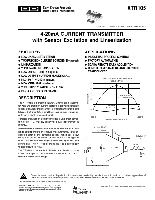
集成电流变送器亦称电流环电路,根据转换原理的不同可划分成以下两种类型:一种是电压/电流转换器,亦称电流环发生器,它能将输入电压转换成4~20mA的电流信号(典型产品有1B21,1B22,AD693,AD694,XTR101,XTR106和XTR115);另一种属于电流/电压转换器,也叫电流环接收器(典型产品为RCV420)。
上述产品可满足不同用户的需要。
XTR系列是美国BB(BURR-BROWN)公司生产的精密电流变送器,该公司现已并入TI公司。
该系列产品包括XTR101,XTR105,XTR106,XTR110,XTR115和XTR116共6种型号。
其特点是能完成电压/电流(或电流/电流)转换,适配各种传感器构成测试系统、工业过程控制系统、电子秤重仪等。
1 XTR系列产品的分类及性能特点XTR系列精密电流变送器产品的分类及主要特点详见表1。
表1 XTR系列产品的分类及主要特点2 XTR115型电流变送器的工作原理2.1 性能特点1)它属于二线制电流变送器,内部的2.5V基准电压可作为传感器的激励源。
XTR115可将传感器产生的40~200μA弱电流信号放大100倍,获得4~20mA的标准输出。
当环路电流接近32mA时能自动限流。
如果在脚3与脚5之间并联一只电阻,就可以改变限流值。
2)芯片中增加了+5V精密稳压器,其输出电压精度为±0.05%,电压温度系数仅为20×10-6/℃,可给外部电路(例如前置放大器)单独供电,从而简化了外部电源的设计。
3)精度高,非线性误差小。
转换精度可达±0.05%,非线性误差仅为±0.003%。
4)环路电源电压的允许范围宽,Us=7.5~36V。
XTR115由环路电源供电。
工作温度范围是-40℃~+85℃。
5)专门设计了功率管接口,适配外部NPN型功率晶体管,它与内部输出晶体管并联后可降低芯片的功耗。
2.2 工作原理XTR115采用SO-8小型化封装,其内部电路框图及基本应用电路如图1所示。