Barone中文操作手册
- 格式:docx
- 大小:109.99 KB
- 文档页数:7

斑马打印机常见故障解决1.测完纸后,在不打印的情况下让走纸的话,走出一张标签的比原来出来的靠里了一些。
谢谢。
应该如何调啊!答:按两下MODEL键,position灯亮然后按FEED标签位置前移,按CANCEL键标签位置后退,你可以我公司网站上的下载手册看看。
2.我公司有一台105SE的斑马打印机出现如下故障:测纸正常,但是打印位置经常变动,请指教!如何解决,急!~急!急!105se能打印宽是30MM高是10mm的标签吗!答:是怎么变动?如果是上下的话是因为你的标签高小于1。
2cm,在打印时一般要设定label top 位置。
3.最近我公司的105sl老是在打印时在标签纸上出现黑色的线影响扫码,不知是何故,求答答:打印头太脏了!请仔细清洗打印头!4.请问一下:ZEBRA 170XI III在切纸时,能否设置标签不回卷呢?谢谢!答:一般是要回退的,否则切纸不准。
5.我们105SE 原可打印中文,后"BAR-ONE"程序不幸卸载,重装后就不能打印中文了,请指教如何设置.谢谢答:安装完后修改:BIN下SETUP.INI 文件{printer1}";TTFSizeThreshold=1"去掉分号,在其下加以下一行“TTFROTATETHRESHOLD=1” 。
6.我有一台ZBERA140XI的打印机出现一开机错误指示灯亮屏幕显示:ERROR CONDITION RIBBON OUT 请问这是那里出问题了.谢谢答:出现这种错误说明打印机检测不到碳带.清洗碳带传感器,再恢复出厂设置试试。
7.我们公司的zebra 105se打印机连在计算机的com口上不能打印测试页,也无法获取打印机信息,但是在打印测试页时打印机的DA TA灯会闪烁两次,虽然不能打印。
答:对串口机器来说,电脑与打印机的串口通信协议是要一致才可以的。
8. 我的打印机是zebras400tm的现打出来的标签很模糊,,而且右边一张纸只能打印一半,,恳请指教,,不胜感激,答:在打印机属性里面将打印的黑度调高,试试。

1.电池手柄①连接点②轨道③释放滑块④安全开关⑤触发点⑥充电指示灯(不是PH09)⑦LED 灯(不是PH09)⑧带环2.特点和操作方法1.请更改驱动方向或者释放这个安全触发点。
当你更换电池或者是其他配件的时候移动到中心位置。
2.阅读手册所有客户用这个机器的时候首先要阅读和理解所有的资料和警告标签关于这台机器和其他材料的。
3.保护视力,听力和呼吸。
4.穿戴合适的衣服。
5.按下触发器,通过压力来改变控制速度。
6.旋转开关激活LED 工作灯。
7.在这个方向滑动双面到一定位置来释放电池手柄。
8.按下这个地方可显示电量。
9.展开这个带环从手柄的前方,直到click这个位置。
然后再收回到这个click位置。
3.安装电池手柄插入电池手柄对齐电池手柄上的轨道插入工具里面或者是充电直到感觉到他们完全契合和平整。
移开电池手柄握住和滑动两个滑动开关,将电池手柄从机器里拔出来。
LED 指示灯第一个是红灯,第二个是黄灯,第三个是绿灯。
满电的时候是绿灯亮还有一半电池的时候是黄灯亮电池电量低的时候是只有红灯亮。
改变电量按下在电池边上的第一个黑色按钮,他就会显示现在的电量是多少。
红色的灯说明现在电量很低。
红色加黄色的灯说明电池还能维持一段时间。
红色加黄色加绿色一块显示说明是满电。
更换充电过程是这些灯来回循环的过程,先是红灯,黄灯,绿灯然后又红灯,黄灯,绿灯,然后又红灯,这样来回循环下去直到电池充满电。
当所有的灯都亮了不来回的闪了,电池就充满电了。
警告指示温度保护当高温的时候电池的红色灯将不停的显示,这预示着我们要把温度降到75摄氏度或者167 华氏温度。
电流保护高电量消耗导致电池内的电压低(例如工具被卡住时),红色的灯会快速闪烁10秒,打开卡住之物,重新启动该工具。
充电注意:电池充电必须提供充足的电量,确保电池能完好的充满电,第一次使用前必须给电池充满电。
电池要保持干燥,不要进水。
必须有特定的充电器给电池充电或者其他可以代替的东西。

1 打印机出现错误的若干情况会有几种错误会影响打印机的正常打印。
有些会停止打印机的操作,而另一些只是会提醒操作者,并不会影响打印。
打印头打开错误就会使整个打印机停止打印操作。
而打印头温度偏低,则不会影响具体的使用。
仍能正常操作。
标签用完错误,碳带用完错误,打印头打开错误,切刀错误用完标签,用完碳带,切刀错误。
会使打印机停止打印。
然后使得error 灯常亮。
而打印头打开错误,刚会使error 灯闪烁。
一旦出现以上一个或几个错误,打印机的Pause灯就会变亮。
然后等待用户消除错误。
一旦用户消除了错误,用户可以按下Pause按钮来使打印机处于正常的工作状态。
当然如果打印机在出错之前是处于打印标签的状态。
那么在清除了错误之后打印机仍旧会继续先前的打印。
打印头太热当打印头变得太热,所有的打印任务全部会停止。
然后error 灯就会闪的较慢。
一旦打印头的温度恢复到正常状态,打印机就会继续打印它的任务。
出现打印头过热时,打印机的其它功能任然是正常的。
例如Feed和calibrate 都是比较正常的。
打印头太冷打印机将会出现类似的情况,当打印头的温度变得比较低时。
但是有所不同的是,打印机并不会停止打印。
只是error 灯会较慢的闪烁。
所以打印头温度过低并不会影响正常使用。
电源太热当电源变得很热时,所有的打印作业全部会停止。
此时error 灯将会较慢的闪烁。
当其温度重新降下来时,打印机将会继续正常打印。
它的现象类似于打印头过热。
4 经常遇到的一些和软件相关的问题的解决方案1我用ZEBRA机器的随机软件BARONE不能打印中文。
答:请进入BARONE的安装目录,然后进入BIN目录。
修改setup.ini.在printer 下面的语句前所有的分号全部删掉。
这些语句是:TTFSizeThreshold=1TTFROTATETHRESHOLD=1Rotatethreshold=1然后进入BarOne程序就可以打中文了。
记住要选中文字体。
Product no: SA-BERG0-000RRF no: 40 10 2244Last updated: 01.01.2013NO Monterings- og bruksanvisning 2GB Installation- and user manual 9SE Installations- och bruksanvisning 15 FIKättöohje219EN1. Prior to assembling the stoveAll our products are tested according to the latest European requirements and also to the Norwegian standard NS 3058 and NS 3059, which include particle tests. However, several European countries have local regulations for installation of fireplaces, which change regularly. It is the responsibility of the client that these regulations are complied with in the country/region where the fireplace is installed. Nordpeis AS is not responsible for incorrect installation.Important to check(please note that this list is not exhaustive):• distance from firebox to combustible/flammablematerials• insulation materials/requirements betweenfireplace surround and back wall• size of floor plates in front of fireplace if required • flue connection between firebox and chimney • insulation requirements if flue passes through aflammable wall Chimney draftCompared with older models, the clean burning stoves of today put significantly higher demands on the chimney. Even the best stove will not work properly if the chimney does not have the right dimensions or is not in good working order. The draught is mainly controlled by gas temperature, outside temperature, air supply as well as the height and inner diameter of the chimney. The diameter of the chimney should never be less than that of the flue/chimney collar. At nominal effect there should be a negative pressure of 12 to 25 Pascal.The draught increases when:• The chimney becomes warmer than the outside air • T he active length of the chimney over the hearth increases • G ood air supply to the combustion It can be difficult to obtain the right draught conditions in case the chimney is too large relative to the stove, as the chimney does not heat up well enough. In such cases you may want to contact professional for evaluation of possible measures. Draught that is too strong can be controlled with a damper. If necessary, contact a chimney sweeper.Air supplyA set for fresh air supply is available as accessory. This will ensure that the air supply to the combustion chamber is less affected by ventilation systems, kitchen fans and other factors which can create a down-draught in the room. In all new construction, we strongly recommend that it is designed and prepared for direct supply of outside air. In older houses, the use of fresh air supply set is also recommended. Insufficient air supply can cause down-draught and thereby low combustion efficiency and the problems that this entails: soot stains on the glass, inefficient use of the wood and a soot deposits in the chimney.1. Prior to assembling the stove 9Chimney draft 9Air supply 9Dimensional drawing 102. Technical information103. Distance to combustible material 104. Assembly10Operating control 10Flue outlet collar10Connection of the flue 10Fresh air supply115. Lighting the fire for the first time116. Maintenance 11Cleaning and inspection 11Ashes 11Thermotte™ 11Door and glass 127. Warranty128. Advice on lighting a fire12Some advice in case of combustion problems14INDEX10ENdown to ember.3. Distance to combustible materialEnsure that the safety distances are respected (FIG 1).When connecting a steel chimney to the top outlet use the security distances required from the manufacturer.4. AssemblyThe following tools are necessary:• ScrewdriverThe stove must be lifted from vertical position. Do not tilt! It can damage the legs.Operating controlWhen the stove is in position, check that all functions are easy to manoeuvre and appear satisfactory.DoorHandle turned downward Handle turned upwardClosed OpenedIgnition vent control FIG A (bottom centre) Air vent control FIG B (bottom left corner)Left position = closed Right position = openPushed in = closedPulled out = openFIG A FIG BFlue outlet collarBergen is delivered as standard with a top flue outlet collar. In order to change to a posterior mounted flue outlet :FIG 2:Remove the perforated decoration lid in the back with a hammer, or saw it out with a hacksaw FIG 3: Unscrew the rear sheet steel lidFIG 4: Unscrew the top collar. The draft diverter will also loosenFIG 5: Fasten the collar on the posterior flue outlet FIG 6: Fasten the sheet steel lid and the draft diverter on the top flue outletConnection of the fluePlease be aware when connecting the 155 mm flue to the smoke dome that the flue is placed inside the flue outlet collar.*Alternative versions exsists due to National requirements . Dimensional drawingThe illustration indicates the approximate center height of the hole for the flue. Distortions in floors and walls may influence the height. Place the stove for accurate position and height of the flue/chimney connection. We accept no liability for typographical errors and changes.For your own safety, comply with the assembly instructions. All safety distances are minimum distances. Installation of the stove must comply with the current rules and regulations of the country where the product is installed. Nordpeis AS is not responsible for wrongly assembled stoves.Subject to errors and changes.For the latest updated version go to .2. Technical InformationThe stoves from Nordpeis have secondary combustion and are clean burning. The combustion takes place in two phases: first the wood burns and then the gases from the fumes are lit by the hot air. This ensures that these new stoves have minimal emissions of soot particles and unburnt gases (such as CO) and are thus better for the environment. Clean burning stoves require a small amount of wood in order to obtain a good heat output. Use exclusively clean and dry wood. We recommend seasoned hardwood with a maximum moisture content of 20%.Material:Sheet steelSurface treatment door/doorframe: Heat resistant varnish Fuel:Wood logs, 30 cm Operating range: 5 kW nominal Efficiency:84,8%CO % @ 13% O 2:0,10Draught system:Air vent control Combustion system:Secondary combustion (clean burning)Heating area:40-110 m²Flue outlet: Top and rear Flue:Inner Ø 155 mm *Alternative versions exsists due to National requirementsWeight:110 kg Flue gas temperature 239 °CAir supplyrequirements (m³/h):11 Fuel Charge 1,1 kg Refueling interval 47min Opening of the air vent control 33%OperationIntermittent** Intermittent combustion refers to normal use of a fireplace, i.e. new wood is inserted when the previous load has burnedIgnition vent controlAir vent controlFor the flue connection to the chimney, follow the recommendations from the chimney manufacturer. Fresh air supplyFIG 8: The possibility to connect a fresh air supply ducting set5. Lighting the fire for the first timeWhen the stove is assembled and all instructionshave been observed, a fire can be lit. Be careful with touching the stove the first few times it is used as it may damage the varnish.Take care when inserting logs into the burn chamber, in order not to damage the Thermotte plates. Please note that during the first few firings, the insulations panels within the firebox will release moisture contained within them from production. This will slow down the burn rate slightly and could cause markings on the glass. These are easily removed with glass cleaner once the glass has gone cold. Possibly leave the door slightly open the first 2-3 times that the stove is used. It is advisable to ventilate the room well when making the fire for the first time as the varnish on the stove will release some smoke or smell. Both the smoke and smell will disappear and are not hazardous.When lighting the fire for the first time we also recommend opening/shutting the door regularly the first two hours to avoid the door gasket sticking to the varnish.Lighting a fireInsert small dry pieces of wood, ignite and ensure that the flames have a good grip of the wood before closing the door. Open the ignition vent control (Fig A) as you close the door. When the flames are stable and the chimney is warm, close the ignition vent control. If it is not closed the stove and chimney may overheat. The air supply is then regulated with the air vent control (Fig B). NB! If the draught is low after the fire has been lit, additional air supply can be added by opening the ignition vent control.When there is a glowing layer of ash, new wood logs can be inserted. Remember to pull the hot ember forward in the burn chamber when inserting new logs so that the wood is ignited from the front. Open the vent or leave the door slightly open each time new logs are inserted so that the flames get established. The fire should burn with bright and lively flames.Using the stove with low combustion effect increases pollution as well as the risk of a fire in the chimney. Never allow the stove or flue to become glowingred. Turn off the air vent control should this happen. Regulation of the air vent control takes some experience, but after a little while a natural rhythm for the fire will be found.IMPORTANT! Always remember to open the air vent control (preferably also the door) before new wood logs are inserted into a hot burn chamber. Let the flames get a good grip on the wood before the air control setting is reduced.When the draught in the chimney is low andthe vent is closed, the gas from the firewoodcan be ignited with a bang. This can cause damages to the product as well as the immediateenvironment.6. MaintenanceCleaning and inspectionThe stove should be inspected thoroughly and cleaned at least once per season (possibly in combinationwith the sweeping of the chimney and chimney pipes). Ensure that all joints are tight and that the gaskets are rightly positioned. Exchange any gaskets that are worn or deformed.Remember that the stove must always be cold when inspected.AshesThe ashes should be removed at regular intervals.Be aware that the ashes can contain hot ember even several days after the fire is finished. Use a container of non-combustible material to remove the ashes. It is recommended to leave a layer of ashes in the bottom as this further insulates the burn chamber. Take care with the Thermotte plates when the ashes are removed, particularly when using an ash shovel, so as not to damage them.Thermotte™The insulating plates in the burn chamber (FIG 9) contribute to a high combustion temperature, which leads to cleaner combustion of the wood and a higher rate of efficiency. Any fissures in the plates will not reduce their insulation efficiency.If new plates are needed, contact your dealer. Please note: Wood logs that are too long can cause strain and crack the plates, due to the tension created between the side plates.In case the Thermotte plates need to be replaced, lift the smoke baffle (A) in order to remove the sideplates.A. Smoke baffleB. Left side plateC. Back plateD. Back plateE. Right side plateF. Bottom platePlease note that the Thermotte plates may release coloured dust when touched. Avoid touching any cast iron parts with dust on your fingers. Any visible dust on cast iron can be brushed off with a dry cloth.11ENDoor and glassShould there be any soot on the glass it may be necessary to clean it. Use dedicated glass cleaner. (NB! Be careful, detergents can damage the varnish and gaskets). If different detergents are used they may damage the glass. A good advice for cleaning the glass is to use a damp cloth or kitchen roll paper and apply some ash from the burn chamber. Rub around the ash on the glass and finish off with a piece of clean and damp kitchen roll paper. NB! Only clean when the glass is cold.Check regularly that the transition between the glass and the door is completely tight. Possibly tighten the screws that hold the glass in place - but not too hard, as this can cause the glass to crack. Periodically, it may be necessary to change the gaskets on the door to ensure that the burn chamber is air tight and working optimally. These gaskets can be bought as a set including ceramic glue.Recycling of the ceramic glassCeramic glass cannot be recycled. Old glass, breakage or otherwise unusable ceramic glass, must be discarded as residual waste. Ceramic glass has a higher melting temperature, and can therefore not be recycled together with glass. In case it would be mixed with ordinary glass, it would damage the raw material and could, in worst case end the recycling of glass. It is an important contribution to the environment to ensure that ceramic glass does not end up with the recycling of ordinary glass.Packaging recycleThe packaging accompanying the product should be recycled according to national regulations.7. WarrantyFor detailed description of the warranty conditions see the enclosed warranty card or visit our website 8. Advice on lighting a fireThe best way to light a fire is with the use of lightening briquettes and dry kindling wood. Newspapers cause a lot of ash and the ink is damaging for the environment. Advertising flyers, magazines, milk cartons and similar are not suitable for lighting a fire. Good air supply is important at ignition. When the flue is hot the draught increases and door can be closed.Warning: NEVER use a lighting fuel such as petrol, karosine, alcohol or similar for lightinga fire. This could cause injury to you as wellas damaging the product.Use clean and dry wood with a maximum moisture content of 20%. The wood should be dried for a minimum of 6 months after it is cut. Humid wood requires a lot of air for the combustion, as extra energy/ heat is required for drying the humid wood and the heat effect is therefore minimal. This in addition creates soot in the chimney with the risk of creosote and chimney fire.Storing of woodIn order to ensure that the wood is dry, the tree should be cut in winter and stored during the summer, covered and in a location with adequate ventilation. The wood pile must never be covered by a tarpaulin lying against the ground as the tarpaulin will then act as a sealed lid that will prevent the wood from drying. Always keep a small amount of wood indoors for a few days before use so that moisture in the surface of the wood can evaporate.UsageNot enough air to the combustion may cause the glass to soot. Hence, supply the fire with air just after the wood is added, so that the flames and gases in the combustion chamber are properly burnt. Open the air vent and have the door slightly ajar in order for the flames to establish properly on the wood.Note that the air supply for the combustion also canbe too large and cause an uncontrollable fire that very quickly heats up the whole combustion chamber to an extremely high temperature (when using with a closed or nearly closed door). For this reason you should never fill the combustion chamber completely with wood.It is recommended to keep an even fire with a small amount of wood. Too many logs put on hot ember, may result in combustion air starvation, and the gases will be released unburnt. For this reason it is important to increase the air supply just after adding logs.Choice of fuelAll types of wood, such as birch, beech, oak, elm, ash and fruit trees, can be used as fuel in the insert. Wood species have different degrees of density - the more dense the wood is, the higher the energy value. Beech,12 ENoak and birch has the highest density.Attention! We do not recommend using fuelbriquettes/ compact wood in our products. Use ofsuch fuel may cause the product to overheat andexceed the temperatures determined safe.Burning briquettes/ compact wood is done so atyour own risk and only small amounts (max 1/3 ofnormal load) should be used for each load.Warning:NEVER use impregnated wood, painted wood,plywood, chipboard, rubbish, milk cartons,printed material or similar. If any of these itemsare used as fuel the warranty is invalid.Common to these materials is that duringcombustion they can form hydrochloricacid and heavy metals that are harmful tothe environment, yourself and the insert.Hydrochloric acid can also corrode the steel inthe chimney or masonry in a masonry chimney.Also, avoid burning with bark, sawdust or otherextremely fine wood, apart from when lightinga fire. This form of fuel can easily cause aflashover that can lead to temperatures that aretoo high.Warning:Make sure the insert is not overheated - it cancause irreparable damage to the product. Suchdamage is not covered by the warranty.Source “Håndbok, effektiv og miljøvennlig vedfyring” by EdvardKarlsvik SINTEF Energy Research AS and Heikki Oravainen, VTT.http//EN13Some advice in case of combustion problems14 ENFIG 1=Brannmur/Brandmur/Palomuuri//Firewall/Mur parefeu/Hitzenschutzwand=Brennbart materiale/Brændbart materiale/ Brännbart material/ Tulenarka materiaali/Combustible material Matières combustibles/Brennbarem Material2930Nordpeis AS, Gjellebekkstubben 11, N-3420 LIERSKOGEN, Norwaywww.nordpeis.no。
Barone中文操作手册Zebra Bar-one使用说明Version Update HistoryDate Reason/Progress Version Initialization/RevisionContent1软件的安装及运行3 1.1安装Bar-one5.0软件 (3)1.2运行程序 (5)2软件的设置与运行5 2.1菜单及按钮说明 (5)2.2选择打印机 (6)2.3新建标签文檔 (6)2.4设置标签文档 (6)2.5条形码设定 (7)2.6打印文本 (8)2.7画线 (8)2.8画圆 (8)2.9画矩形 (8)2.10添加图形 (8)2.11添加变数(以流水号为例) (9)2.12给流水号加前缀或后缀 (10)2.13设置打印参数 (11)3打印标签11 3.1测试打印 (11)3.2连续打印 (12)3.3产生机器码 (12)1软件的安装及运行1.1安装B a r-o n e5.0软件Bar-one5.0存放在公用文件夹\\auskit\Public\BAR-ONE在此目录找到【setup.exe】”这个文件并双击它,软件开始安装→再在选择语言中选取【英语】,→单击【确定】,安装程序继续,→再单击【Next】,→【Yes】,在如下的对话框中填入用户姓名、公司名称,在Serial中输入如图所示的序列号(\\auskit\Public\BAR-ONE\sn.txt中有序列号),→再单击【Next】出现如下的对话框(单击Browse 可更改安装路径)→再四次单击【Next】, 出现如下的对话框,在Printer List栏选择打印机为【Z105S/105SE -300dpi】,Port选择【COM1】,Baud Rate:选择【9600】,Data Bits:选择【8】,Parity:选择【None】,Stop Bits:选择【1】,Flow Control:选择【X-ON】→然后单击【Next】,安装程序将自动完成安装工作。
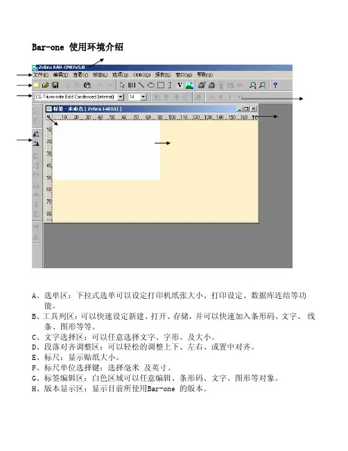
Bar-one 使用环境介绍A、选单区:下拉式选单可以设定打印机纸张大小、打印设定、数据库连结等功能。
B、工具列区:可以快速设定新建、打开、存储,并可以快速加入条形码、文字、 线条、图形等等。
C、文字选择区:可以任意选择文字、字形、及大小。
D、段落对齐调整区:可以轻松的调整上下、左右、或置中对齐。
E、标尺:显示贴纸大小。
F、标尺单位选择键:选择毫米 及英寸。
G、标签编辑区:白色区域可以任意编辑、条形码、文字、图形等对象。
H、版本显示区:显示目前所使用Bar-one 的版本。
设定打印机1、由文件下拉式菜单拉下选择打印设置。
2、 选择主打印机按鼠标左键一下。
3、 如此可进入打印机设定画面。
设定打印机画面说明:1、打印机类型:选择适用的机型,不同的机型在打印类型会有不同的选项可供设定。
2、端口:选择端口连接(如COM1,COM2,LPT1 等)。
3、配置按键:设定串口通讯参数。
4、选项:(a)每批打印完后暂停(b)每次打印前删除已下载的暂存对象(c)用图形方式产生二维条码(d)印完一批次后,送一张空白贴纸。
5、每次进行状态检查 –设定软件每n 秒自动检查条形码机状态。
6、打印模式设定。
7、打印机初始化字符串 :打印机初始设定,可直接ZPLII指令控制。
8、自动作业提交: 可由设定的目录下直接固定n 秒钟自动执行打印。
标签纸设定:1、标签尺寸 :宽度和高度的设定。
2、边界 :设置左边起始位置和顶端起始位置。
3、单位 :单位设定毫米或英寸。
4、标签说明 :可对此规格大小贴纸作描述,若贴纸种类很多的客户可便于不容易并错。
5、媒介细节 :设定使用连续纸式不连续纸,是否使用黑线Mark感测器。
6、复制标签 :设定打印张数由某个ID,并可设定相同标签打印张数。
1、由工具列点条形码的图标。
2、设定条形码种类高度、宽窄、比例。
3、可设定条码内容识别文字显示位置。
4、可直接定义 X 轴及 Y 轴位置。
5、数据来源有多种选择如高级,固定,日期,串号等6、本范例由高级选项中,按定义后。

斑马打印机在使用过程中常常遇到一些问题,我们在长期销售、使用斑马条码打印机中,遇到的一些常见故障,总结列表如下,并给出调整办法,希望能对我们的用户使用斑马机有所帮助。
1、打印机出现错误的若干情况会有几种错误会影响打印机的正常打印。
有些会停止打印机的操作,而另一些只是会提醒操作者,并不会影响打印。
·打印头打开错误就会使整个打印机停止打印操作。
而打印头温度偏低,则不会影响具体的使用。
仍能正常操作。
·标签用完错误,碳带用完错误,打印头打开错误,切刀错误用完标签,用完碳带,切刀错误。
会使打印机停止打印。
然后使得error灯常亮。
而打印头打开错误,刚会使error灯闪烁。
一旦出现以上一个或几个错误,打印机的Pause灯就会变亮。
然后等待用户消除错误。
一旦用户消除了错误,用户可以按下Pause按钮来使打印机处于正常的工作状态。
当然如果打印机在出错之前是处于打印标签的状态。
那么在清除了错误之后打印机仍旧会继续先前的打印。
·打印头太热:当打印头变得太热,所有的打印任务全部会停止。
然后error灯就会闪的较慢。
一旦打印头的温度恢复到正常状态,打印机就会继续打印它的任务。
出现打印头过热时,打印机的其它功能任然是正常的。
例如Feed,和calibrate都是比较正常的。
·打印头太冷:当打印头的温度变得比较低时,打印机将会出现类似的情况。
但是有所不同的是,打印机并不会停止打印。
只是error灯会较慢的闪烁。
所以打印头温度过低并不会影响正常使用(除非极其低)。
·电源太热:当电源变得很热时,所有的打印作业全部会停止。
此时error 灯将会较慢的闪烁。
当其温度重新降下来时,打印机将会继续正常打印。
它的现象类似于打印头过热。
以下是一些错误情况下ERROR灯闪烁的情况面板的LED灯、打印头打开、碳带用完、标签用完、打印头太冷、打印头太热、电源太热,Error 灯较快的闪烁常亮常亮较慢的闪烁较慢的闪烁较慢的闪烁2、LED 显示的错误提示及错误报告:Ribbon Out问题解决方案在热转印的状态下,碳带没有装好请重新装碳带;在热转印的状态下,碳带传感器没有很好的测出碳带值请重新认纸及碳带<;在热敏方式下,而碳带没有被使用请移掉碳带,并确认驱动和软件的设置是对的Paper out问题纸没有装,或者纸没有装对:重新装纸;传感器没有移到较好的位置:移动反射传感器到合适的位置;打印机设置的是非连续纸,但是使用的是连续纸:重新设置打印机到合适的纸张类型,确认打印机驱动中的设置是正确的,重新认纸;介质传感器没有选择好:选择菜单中的sensor select 并重新选择sensor。

POWERBrazerNovember,2008For use with machines having Code Numbers:11535Safety Depends on YouHarris Brazing,Soldering and cutting equipment is designed and built with safety in mind.However,your overall safety can be increased by proper installation ...and thoughtful opera-tion on your part.DO NOT INSTALL,OPERATE OR REPAIR THIS EQUIPMENT WITHOUT READING THIS MANUAL AND THE SAFETY PRECAUTIONS CONTAINED THROUGHOUT.And,most importantly,think before you act and be careful.Copyright ©Lincoln Global Inc.IP21a Division of Lincoln ElectricIM987This manual covers equipment which is nolonger in production by The Lincoln Electric Co. Speci cations and availability of optional features may have changed.AUG085.c.The operation of brazing fume control equipment is affectedby various factors including proper use and positioning of the equipment,maintenance of the equipment and the spe-cific welding procedure and application involved.Worker exposure level should be checked upon installation and periodically thereafter to be certain it is within applicable OSHA PEL and ACGIH TLV limits.5.d.Read and understand the manufacturerʼs instructions for thisequipment and the consumables to be used,including the material safety data sheet(MSDS)and follow your employerʼs safety practices.MSDS forms are available from your welding distributor or from the manufacturer.AUG08Aug,08Mar.ʻ93vvfor selecting one of our QUALITY products. We want you to take pride in operating this product ••• as much pride as we have in bringing this product to you!SAFETY..............................................................................................................................................................i-ivINSTALLATION....................................................................................................................................SECTION A Technical Specifications.................................................................................................................................A-1 Safety Precautions..........................................................................................................................................A-2 Location.............................................................................................................................................................A-2 Procedures to Install Drive Rolls and Wire Guides....................................................................................A-2 _____________________________________________________________________________________ OPERATION..........................................................................................................................................SECTION B Safety Precautions..........................................................................................................................................B-1 User Serviceability...........................................................................................................................................B-1 General Description.........................................................................................................................................B-1 Recommended Processes and Equipment..................................................................................................B-1 Case Front Controls........................................................................................................................................B-2 Internal Controls..............................................................................................................................................B-3 Rear Controls...................................................................................................................................................B-4 _____________________________________________________________________________________ACCESSORIES....................................................................................................................................SECTION C Drive Roll Kits, Steel Wire..............................................................................................................................C-1 _____________________________________________________________________________________ MAINTENANCE....................................................................................................................................SECTION D Safety Precautions..........................................................................................................................................D-1 Routine Maintenance......................................................................................................................................D-1 Periodic Maintenance.....................................................................................................................................D-1 Calibration Specifications...............................................................................................................................D-1 _____________________________________________________________________________________TROUBLESHOOTING GUIDE............................................................................................................SECTION E How to Use the Troubleshooting Guide.......................................................................................................E-1 Troubleshooting Guide....................................................................................................................................E-2 _____________________________________________________________________________________ WIRING DIAGRAM AND DIMENSIONS...........................................................................................SECTION F _____________________________________________________________________________________ PARTS PAGES................................................................................................................................P-589 SERIES _____________________________________________________________________________________A-1A-1INSTALLATIONTECHNICAL SPECIFICATIONS – POWERBrazer (K2772-1)A-2INSTALLATIONA-2rolls.5. Remove the inner wire guide.6. Insert the new inner wire guide, groove side out,over the two locating pins in the feed plate.Install a drive roll on each hub assembly securewith the triangular lock.8. Install the outer wire guide by aligning it with thepins and tightening the knurled thumbscrews.9. Close the idle arm and engage the idle roll pressurearm. Adjust the pressure appropriately.B-1 B-1FUMES AND GASES can bedangerous.•Keep your head out of fumes.•Use ventilation or exhaust toremove fumes from breathingzone.BRAZING MATERIALS MAY CONTAIN CADMIUM. FUMESARE POISONOUS AN CAN KILL.• Do not breathe fumes. Even brief exposure to high concen-trations should be avoided.• Use enough ventilation, exhuast at the arc, or both, to keepfumes and gases from your breathing zone and generalarea. If this cannot be done, use air supplied respirators.----------------------------------------------------------------------------------------• Do not wear gloves when threading orchanging wire spool.• Keep hands, hair, clothing and tool awayfrom rotating equipment.----------------------------------------------------------------------------------------FLAME and BRAZING SPARKScan cause fire or explosion.• Keep flammable materialaway.------------------------------------------------------------------------------OPERATIONGENERAL DESCRIPTIONThe POWERBrazer is a specially engineered wirefeeder for brazing materials. As part of a patentpending process, the POWERBrazer bringsproductivity and efficiency gains to brazingcustomers. A simple press of a button on the gunfeeds brazing wire at a controlled speed.The heart of the POWERBrazer is the 2 rollMAXTRAC™ drive. The patented features on thewire drive offer tool-less changing of the drive rollsand wire guides for quick spool changes. Atachometer controlled motor powers the patentpending drive rolls for smooth, steady feedingwithout slippage.With only one printed circuit board, thePOWERBrazer is designed to be simple, reliableand easy to service.RECOMMENDED PROCESSESAND EQUIPMENTK1500-1 Gun Bushing InstalledRECOMMENDED PROCESSES• Semi-Automatic BrazingPROCESS LIMITATIONS• The POWERBrazer is intended for brazing only.It cannot be used for arc welding.EQUIPMENT LIMITATIONS• The maximum spool size is 45lbs.(20.4Kg.),12”(305mm) diameter.• Maximum gun length is 15 ft.(4.6m). SAFETY PRECAUTIONSREAD AND UNDERSTAND ENTIRE SECTIONBEFORE OPERATING MACHINEUSER SERVICEABILITYThe serviceability of a product or structure utilizing thePOWERBrazer is and must be the sole responsibilityof the builder/user. Many variables beyond the controlof the Harris Products Group affect the resultsobtained in using the POWERBrazer. These variablesinclude, but are not limited to, brazing procedure,plate chemistry and temperature, joint design, fabrica-tion methods and service requirements. The availablerange of the POWERBrazer may not be suitable for allapplications, and the builder/user is and must be sole-ly responsible for welding settings.B-2B-2OPERATIONCASE FRONT CONTROLSINTERNAL CONTROLSREAR CONTROLS12ACCESSORIESC-1C-1ELECTRIC SHOCK can kill.• Only qualified personnel should perform this installa-tion.• Only personnel that have read and under-stood the POW ERBrazer Operating Manual should install and operate this equipment.• The POW ERBrazer must be plugged into a receptacle which is grounded per any nation-al, local or other applicable electrical codes.• The POW ERBrazer power switch is to be in the OFF (“O”) position when connecting the power cord to the input power.--------------------------------------------------------------------ROUTINE MAINTENANCE• Check cords and the brazing gun for cuts and damage.• Clean and tighten all weld terminals.PERIODIC MAINTENANCE• Clean the drive rolls and inner wire guide and replace if worn.• Blow out or vacuum the inside of the feeder.CALIBRATION SPECIFICATIONWire Feed Speed Validation:Calibration of the POWERBrazer may be required when the printed circuit board, wire feed speed potentiometer or motor is replaced or serviced.Calibration matches the scale on the name plate to the actual wire feed speed.Tools required:• RPM meter• 7/16” open end wrench.To verify if calibration is necessary:1. Turn power OFF.2. Set the wire feed speed to 100 in/min.3. Remove the plastic cover from the lower portion of the wire drive with a 7/16” wrench.4. Turn power ON.5. Measure the motor rpm when the COLD FEED button is pressed.6. Verify the rpm is within 16 – 19 rpm.MAINTENANCETo change the wire feed speed calibration:(See Figure D.1)Tools required:• 5/16" nut driver • RPM meter• Shorting plug. The shorting plug shorts pins 4 and 8 of connector J3on the printed circuit board. J3is an 8pin molex connector.1. Unplug the POWERBrazer.2. Remove the (4) screws holding the rear cover inside the feeder and remove the cover.3. Open the idle arm.4. Set the wire feed speed to 100 in/min.5. Disconnect the fan connector from J3.6. Plug in the POWERBrazer and turn power ON.7. Insert the shorting plug into connector J3 on the print-ed circuit board.8. Remove the shorting plug. 9. Turn power OFF.10. Reconnect the fan connector into J3.11. Replace the cover and secure with the screws.FIGURE D.1D-1D-1TROUBLESHOOTINGThis Troubleshooting Guide is provided to help you locate and repair possible machine malfunctions.Simply follow the three-step procedure listed below.Step 1.LOCATE PROBLEM (SYMPTOM).Look under the column labeled “PROBLEM (SYMP-TOMS)”. This column describes possible symptoms that the machine may exhibit. Find the listing that best describes the symptom that the machine is exhibiting.Step 2.POSSIBLE CAUSE.The second column labeled “POSSIBLE CAUSE” lists the obvious external possibilities that may contributeto the machine symptom.Step 3.RECOMMENDED COURSE OF ACTIONThis column provides a course of action for the Possible Cause, generally it states to contact your local Authorized Field Service Facility.If you do not understand or are unable to perform the Recommended Course of Action safely, contact your local Authorized Field Service Facility.HOW TO USE TROUBLESHOOTING GUIDEService and Repair should only be performed by Factory Trained Personnel. Unauthorized repairs performed on this equipment may result in danger to the technician and machine operator and will invalidate your factory warranty. For your safety and to avoid Electrical Shock, please observe all safety notes and precautions detailed throughout this manual.__________________________________________________________________________Observe all Safety Guidelines detailed throughout this manualE-1E-1TROUBLESHOOTINGWIRING DIAGRAMF-1F-1T E : T h i s d i a g r a m i s f o r r e f e r e n c e o n l y . I t m a y n o t b e a c c u r a t e f o r a l l m a c h i n e s c o v e r e d b y t h i s m a n u a l. T h e s p e c i f i c d i a g r a m f o r a p a r t i c u l a r c o d e i s p a s t e d i n s i d e t h e m a c h i n e o n o f t h e e n c l o s u r e p a n e l s . I f t h e d i a g r a m i s i l l e g i b l e , w r i t e t o t h e S e r v i c e D e p a r t m e n t f o r a r e p l a c e m e n t . G i v e t h e e q u i p m e n t c o d e n u m b e r .DIMENSIONSF-2F-2NOTESNOTES POWERBrazerJapaneseChineseKoreanArabicREAD AND UNDERSTAND THE MANUFACTURER’S INSTRUCTION FOR THIS EQUIPMENT AND THE CONSUMABLES TO BE USED AND FOLLOW YOUR EMPLOYER’S SAFETY PRACTICES.SE RECOMIENDA LEER Y ENTENDER LAS INSTRUCCIONES DEL FABRICANTE PARA EL USO DE ESTE EQUIPO Y LOS CONSUMIBLES QUE VA A UTILIZAR, SIGA LAS MEDIDAS DE SEGURIDAD DE SU SUPERVISOR.LISEZ ET COMPRENEZ LES INSTRUCTIONS DU FABRICANT EN CE QUI REGARDE CET EQUIPMENT ET LES PRODUITS A ETRE EMPLOYES ET SUIVEZ LES PROCEDURES DE SECURITE DE VOTRE EMPLOYEUR.LESEN SIE UND BEFOLGEN SIE DIE BETRIEBSANLEITUNG DER ANLAGE UND DEN ELEKTRODENEINSATZ DES HER-STELLERS. DIE UNFALLVERHÜTUNGSVORSCHRIFTEN DES ARBEITGEBERS SIND EBENFALLS ZU BEACHTEN.JapaneseChineseKoreanArabicLEIA E COMPREENDA AS INSTRUÇÕES DO FABRICANTE PARA ESTE EQUIPAMENTO E AS PARTES DE USO, E SIGA AS PRÁTICAS DE SEGURANÇA DO EMPREGADOR.a Division of Lincoln Electric• World's Leader in Welding and Cutting Products •• Sales and Service through Subsidiaries and Distributors Worldwide •4501 Quality Place, Mason, Ohio 45040 U.S.A. • Web Site: 。

斑马5.0得注册码:1-46953-123-12345-123456-z一维条码本身是不能包含中文字符的,但是如果标签中有需要打印中文的地方出现乱码,那主要的原因出在您的打印软件上。
如果您用的是斑马公司的BARONE 5.0或以下版本,必须在其软件的安装目录中的BIN目录中找到SETUP.INI文件,打开其文件占到PRINT1段,把该段最后三行中前面带“;”中的分号去掉,即可打印中文。
如果有,可按下面的方法解决;将BARONE\BIN\SETUP.INI 作一下修改,保存后打印就应该正常了.找到此语句:NoEscape=N,在此语句后面增加TTFSizeThreshold=1TTFRotateThreshold=1保存后,再打开BARONE打印即可. 或者换一套软件!1.测完纸后,在不打印的情况下让走纸的话,走出一张标签的比原来出来的靠里了一些。
谢谢。
应该如何调啊!答:按两下MODEL键,position灯亮然后按FEED标签位置前移,按CANCEL键标签位置后退,你可以我公司网站上的下载手册看看. ................................................................2.我公司有一台105SE的斑马打印机出现如下故障:测纸正常,但是打印位置经常变动,请指教!如何解决,急!~急!急!105se能打印宽是30MM高是10mm的标签吗!答:是怎么变动?如果是上下的话是因为你的标签高小于1。
2cm,在打印时一般要设定label top 位置................................................................3.最近我公司的105sl老是在打印时在标签纸上出现黑色的线影响扫码,不知是何故,求答答:打印头太脏了!请仔细清洗打印头!................................................................4.请问一下:ZEBRA 170XI III在切纸时,能否设置标签不回卷呢?谢谢!答:一般是要回退的,否则切纸不准................................................................5.我们105SE 原可打印中文,后"BAR-ONE"程序不幸卸载,重装后就不能打印中文了,请指教如何设置.谢谢答:安装完后修改:BIN下SETUP.INI 文件{printer1}";TTFSizeThreshold=1"去掉分号,在其下加以下一行“TTFROTATETHRESHOLD=1”................................................................6.我有一台ZBERA140XI的打印机出现一开机错误指示灯亮屏幕显示:ERROR CONDITION RIBBON OUT 请问这是那里出问题了.谢谢答:出现这种错误说明打印机检测不到碳带.清洗碳带传感器,再恢复出厂设置试试................................................................7.我们公司的zebra 105se打印机连在计算机的com口上不能打印测试页,也无法获取打印机信息,但是在打印测试页时打印机的DATA灯会闪烁两次,虽然不能打印。
产品特性 -------------------------------------------------------1-2 Features产品安装说明---------------------------------------------------3 Notice for Assembly电机安装 -------------------------------------------------------4 Moters Assembly电池盒安装 ----------------------------------------------------5 Battery Holder Assembly车轮安装--------------------------------------------------------6 Wheels Assembly开关及插座安装 ------------------------------------------------7 Power Jack and Switch Assembly红外传感器支架安装--------------------------------------------8IR Sensor Bracket Assembly车身上板安装---------------------------------------------------9 Upper Deck Assembly编码盘安装-----------------------------------------------------10 Encoder Wheel Assembly编码器安装-----------------------------------------------------11 Encoder Sensor Assembly零部件清单------------------------------------------------------12-14 Parts List整机尺寸:简介:Baron-4WD Mobile Platform四轮驱动机器人是DFRobot研制的机器人实验平台,该平台不但可以用51控制、STC控制器、AVR控制器控制外,更适合使用世界上广泛推广的Arduino控制器,Arduino开放平台拥有全球众多使用者,有丰富的使用例子程序。
Dixon800 High Street • Chestertown, MD 21620ph: 877.863.4966 fax: 800.283.4966Section 650 Ton Ram Operating InstructionsforBoss Ground Joint Holedall™ Couplings1877.963.4966 • Section 6: Operating 12Install the 6" Main Pusher (MPUSH600) by sliding it onto the rod cap of the ram cylinder. Make sure that the pusher is all the way on the rod cap. Install the appropriate adapter pusher (by coupling size) into the main pusher.34aAccurately measure the hose O.D. with a diameter tape. Eachend of the hose should be measured to guarantee the correct ferrule and die selection. Select the correct ferrule and die based upon the hose free O.D. just measured from the chart.Assuring that the hose end is cut square, chamfer the I.D. of the hose ⅛" at a 45° angle. This will aid in stem insertion. If the hose is to be static grounded, follow hose manufacturers procedure for proper static grounding.Hold the ferrule against the stem collar (sizes 1½" - 3" only). Using a small ruler or other measuring devise, insert it between the stem and ferrule until it contacts the stem collar. Measure the depth at the end of the ferrule. Place a mark on the hose (the hose end to be assembled) that corresponds with this measurement.877.963.4966 • Section 6: Operating25Lubricate the I.D. of the hose and the O.D. of the stem (as well as possible) with Dixon Coupling Lubricant or equivalent. Insert the stem all the way until the mark on the hose (from Step 4a) is at the end of the ferrule.6a6bBring the hose with the stem and ferrule through the die bed.Position the wing nut (or spud) as close to the pusher as possible. Make sure that there is sufficient room between the die holders and the end of the ferrule to comfortably insert the die halves into the die holders.Install the required die holders ensuring that the seams betweenthe die holder halves do not line up. The die holders are designedto fit one inside the other.A guideline for selecting die holders is:DH3-001 ¼" - 1" I.D. hose 50TDH6003 1¼" - 3" I.D. hose 50TDH9004 4" I.D. hoseCaution! Never use a swaging die as a die holder!Secure the die holders with tie down bars to prevent the die holders from slipping out of the die bed unexpectedly.3877.963.4966 • Section 6: Operating7bLubricate the outside of the ferrule with Crisco ® (recommended) or high viscosity oil or heavy duty grease.8a8bLubricate the I.D. of both die halves with Crisco® (recommended) or high viscosity oil or heavy duty grease.Lifting up the hose, insert one die half under the hose. Lower the hose so that it rests on the die. Insert the other die half. Make sure that the seams of the die do not line up with the seams on the die holders.While holding the die in place with one hand, place one of the tie down bars over the die so that it does not come out of the die holder unexpectedly. Secure the tie down bar by tightening the bolt.877.963.4966 • Section 6: Operating49bMove the directional control lever to the "FORWARD" position and depress the button on the remote. Advance the cylinder forward until the end of the ferrule is near the die opening. Using a wooden board or metal pipe, lift the ferrule up. Jog the cylinder by depressing and releasing the button on the remote. This will allow the ferrule to enter the die slowly. After the ferrule has entered the die, stop advancing the cylinder.9c10aAlign the wing nut (or spud) with the pusher ensuring they are flush with each other. Jog the cylinder forward until pressurebegins to register on the gauge. Leave the directional control lever in the "FORWARD" position. Check the alignment betweenpusher and wing nut (or spud). If any adjustment is necessary, doit now.Reposition the tie down bars on the die face so that the wing nut (or spacer) will clear.Depress and hold the button on the remote until the wing nut (or spacer) contacts the die face. Release the button. Return the directional control lever to the "NEUTRAL" position.Note: For ¾" and 1" couplings having the ferrule crimped on, stop the swage when the crimped area of the ferrule begins to enter the die.Note: If the gauge reads 10,000 PSI before swaging is complete, stop. The ferrule or die used for that hose end may be incorrect. Contact Dixon for further assistance.5877.963.4966 • Section 6: Operating11aMove the directional control lever to the "REVERSE" position and depress the button on the remote. Retract the cylinder until there is sufficient room for the stem and ferrule to clear the die bed.11bPosition a rubber sheet or pad under the die bed. Slowly slidethe hose towards the pusher. When the die clears the die holder, one or both halves may fall to the floor. If one half remains on the ferrule, tap it with a mallet until it releases. If both halves remain on the ferrule, it may require the halves be pried apart at the seam.Wipe excess lubricant from hose and ferrule. Bring hose with stem and ferrule back through die bed.。
百特智能数显表说明书工作状态下按SET显示LOCY→按SET输入密码18→按SET显示RAN9→按SET通过△▽选择分度号→按SET显示Poin设置小数点→按SET显示r9.00设置量程下限→按SET显示r9.FS设置量程上限工作状态下按SET→通过△▽选择COrr按SET显示old.1→按SET通过△▽修正温度值参数设定说明:Locy:菜单上锁操作入口;按SET键确认;按△▽键退出;开锁密码为18Ran9.:分度号和量程设置入口;按SET键确认;按△▽键退出010/…/y:分度号设置;按△▽键设置;按SET确认PoIn:小数点位置设置;按△▽键设置;按SET确认R9.00:量程零点设置;按△▽键设置;按SET确认R9.FS:量程满度设置;按△▽键设置;按SET确认Corr:量程迁移和滤波时间设置菜单入口;按SET 键确认;按△▽键取消Old.1:修正温度值;按△▽键设置;按SET确认按键说明:△:变更参数设定时,用于增加数值SET:参数设定确认键▽:变更参数设定时,用于减少数值常见故障处理:仪表通电不亮:供电电源未接入,正确接入仪表电源;接触不良,取出表芯确认弹片接触是否良好。
LED屏显示:broy分度号选择错,选择与输入信号相符的分度号;输入信号太大,调节与输入信号保证在仪表范围内;信号短线,正确接入信号线。
H.oFL.分度号选择错,选择与输入信号相符的分度号;输入信号太大,调节与输入信号保证在仪表范围内;仪表标定错误,选择正确标定信号重新标定。
L.Ofl.:选择与输入信号相符的分度号;输入信号太小,调节与输入信号保证在仪表范围内;仪表标定错误,选择正确标定信号重新标定昌辉SWP系列智能仪表说明书控制方式:1、正确的接线仪表卡入表盘后,请参照仪表随机接线图接妥输入、输入及电源线,并请确认无误。
2、仪表的上电本仪表与电源开关,接入电源即进入工作状态。
3、仪表设备号及版本号的显示仪表在投入电源后,可立即确认仪表设备号及版本号。
BARCO BARCO大屏幕显示系统软件简明使用手册Apollo控制软件1. 简介在现代应用的大屏幕显示墙上,应用窗口的大小,类型,数量,和位置均没有限制,但这也会容易造成在大屏幕上产生混乱,例如重要的报警窗口被次要的视频窗口所覆盖。
所以在任何情況下一個合适的大屏幕管理软件是不可缺少的,本项目配备了 BARCO 自行开发的Apollo 大屏幕管理软件,它可以:将大屏幕分成不同的区域以达到整齐效果,设定布局 (layouts) 把窗口固定或限制窗口的位置来防止窗口重叠。
要显示特定的信息时会自动启动或停止应用程序及利用预先设定的布局排列窗口将最重要的操作程序自动化,例如遇到紧急情況時切换到特定的显示布局。
监控,安排,管理控制中心內的资源包括显示大屏幕及其他共享的设备。
所有大屏幕管理功能可通过安装在操作者的工作站或大屏幕控制器本身的简易图像介面上选用,在Apollo 大屏幕管理软件中利用鼠标点击便能切换到预设的布局,內含已在布局编辑器中排列及储存的窗口。
相应的应用程序也会自动被启动,这样可使操作者专注于他们日常的实际工作。
显示中的窗口可以就预设的权限和区域被互动地移动或调整大小,但要注意的是操作大屏幕管理软件時并不会影响窗口显示中的內容或因操作一个窗口而影响別的窗口的显示质量。
投影机的参数也可由 Apollo 大屏幕管理软件控制,例如灯泡使用计数器,灯泡开关,状态信息,对比度和亮度都可互动地控制。
Apollo 大屏幕管理软件不仅仅限于管理大屏幕,它也可控制其他外部设备装置,例如UPS,矩阵切换器等,将它们整合成一个操作系统。
如果操作者拥有权限,便可监控所有硬件的参数及作互动式操作,预设的权限防止操作者进行错误或未经授权的操作以保障安全和有效的操作环境。
开放的 Apollo 应用程序介面接口(API) 及指令介面接口 (commandinterfaces) 容许使用者简易地将大屏幕管理软件的功能和客戶的应用程序整合使用,系统整合者可接触大屏幕管理的特点,容許他们自定义操作介面及操作布局,为 Apollo 进行第二次开发。
使用BarOne5.0 列印流水標
by hongping 2012-07-26 一、File(文件)->New(新建文檔)
二、Label->Setup 彈出設置新建的文檔。
本例設置為(寬*高)為(22*10)mm 的標籤,如上圖。
三、依次如下圖創建一個標籤類型為Code128的Serial Number,然後點擊Define。
如下設置當前開始列印流水號為0001,默認最大值9999、最小值0001。
四、上面OK后返回到Barcodes窗口,在下拉框處選擇Advanced項,點擊Define 出現Advanced窗口,在Data definition string文本框中的字符串首位加入要加入的字符串,如下在加入GWT (字符串) H,然後兩次OK確定,在畫布總單擊設置好的標籤。
五、Label->Print Options->Inhibit printer from serializing處打勾,OK退出。
六、最后保存點擊彈出如下框,輸入要列印的數量Print即可。
注意:如果不要掃描條碼,只列印流水文字標則在第三步創建流水標時選擇[V]按鈕,其他操作一樣:。
BAIARDO L 操作手册感谢您购买WILSON BAIARDO L 穿线机。
基于屡获殊荣的 Wilson Baiardo 机器的构造和设计,Baiardo L 为全球穿线工提供一个更简单、更轻便的选择。
主要功能包括:• 比原来的 Wilson Baiardo 轻 20%• 可手动高度调节和倾斜角,从而提供实用的人体工学设计和舒适性• 向内调整安装杆,以更好地适应羽毛球球拍• 五齿夹钳可最大限度地提高抓地力,同时最大限度地减少线绳干扰• 落地支架上的卷轴架支撑线绳卷轴,以增加便利性本手册提供了关于组装和使用 Baiardo 机器的基本信息。
所有方向(右、左、前、后等)均是从穿线期间的穿线工角度给出。
假设用户已穿好球拍,并理解穿线机的基本操作。
更多信息请见 /baiardo.谨上,Baiardo 开发团队1BAIARDO L 操作手册BAIARDO L警告和注意事项 . . . . . . . . . . . . . . . . . . . . . . . . . . . . . . . . . . . . . .3机器装配 . . . . . . . . . . . . . . . . . . . . . . . . . . . . . . . . . . . . . . . . . . . . .3部件说明 . . . . . . . . . . . . . . . . . . . . . . . . . . . . . . . . . . . . . . . . . . . . .4部件描述-羽毛球 . . . . . . . . . . . . . . . . . . . . . . . . . . . . . . . . . . . . .4启动 . . . . . . . . . . . . . . . . . . . . . . . . . . . . . . . . . . . . . . . . . . . . . . . . .5通电 . . . . . . . . . . . . . . . . . . . . . . . . . . . . . . . . . . . . . . . . . . . . . . . . .5基础 . . . . . . . . . . . . . . . . . . . . . . . . . . . . . . . . . . . . . . . . . . . . . . . . .6夹钳和夹钳座 (7)转盘制动器 . . . . . . . . . . . . . . . . . . . . . . . . . . . . . . . . . . . . . . . . . .8调整拉线器机头 . . . . . . . . . . . . . . . . . . . . . . . . . . . . . . . . . . . . . .8机器高度调节 . . . . . . . . . . . . . . . . . . . . . . . . . . . . . . . . . . . . . . . .9摩擦制动器 . . . . . . . . . . . . . . . . . . . . . . . . . . . . . . . . . . . . . . . . . .9倾斜调整 . . . . . . . . . . . . . . . . . . . . . . . . . . . . . . . . . . . . . . . . . . . .10显示界面 . . . . . . . . . . . . . . . . . . . . . . . . . . . . . . . . . . . . . . . . . . . .11维护 . . . . . . . . . . . . . . . . . . . . . . . . . . . . . . . . . . . . . . . . . . . . . . . .16服务 . . . . . . . . . . . . . . . . . . . . . . . . . . . . . . . . . . . . . . . . . . . . . . . .17故障排除 . . . . . . . . . . . . . . . . . . . . . . . . . . . . . . . . . . . . . . . . . . . .19保修信息 . . . . . . . . . . . . . . . . . . . . . . . . . . . . . . . . . . . . . . . . . . . .21BAIARDO L 规范 . . . . . . . . . . . . . . . . . . . . . . . . . . . . . . . . . . . . .222BAIARDO L 操作手册BAIARDO L 操作手册3警告和注意事项妥善保存此类说明。
1.2运行程序
执行【开始】✍【所有程序】✍【Zebra BAR-ONE v5.0】✍单击【Design Program】即可运行程
序,程序初始运行接口如下:
2
2.1菜单及按钮说明
软件运行后如下图所示:
菜单在最上面自左向右为:如下图
【File】-文件, 【Edit】-编辑, 【Veiw】-视图, 【Label】-标签, 【Options】-选项, 【ODBC】-数据库联接, 【Report】-报表, 【Window】-窗口, 【Help】-帮助
按钮在第二行从左向右依次为:
【新建文档】, 【打开文档】, 【保存文档】, 【剪切】, 【复制】, 【粘贴】, 【撤消】, 【重复】, 【指针】, 【条码】, 【线条】, 【圆】, 【字符】, 【变量】, 【图形】, 【测试打印】, 【打印】, 【放大】, 【缩小】, 【帮助】
2.2选择打印机???
单击【File】✍【Printer setup】✍【Main printer】弹出如下图所示
✍在【Printer Type】选项选择Z105S/105SE-300dpi
✍在【Port】选择COM1: 其它使用默认值. ✍单击【OK】完成设定.
2.3新建标签文档
单击【File】✍【New】即可。
2.4设置标签文档
单击【File】✍【Label setup】,或单击【Label】✍【Setup】出现对话框,
如下图所示:
【Label dimensions】中设定标签的宽度和高度, 【Width, Depth】,
【Margins】中设定上边距和左边距【Left, Top】,
【Units】中设定度量单位【mm】-毫米, 【inches】英寸,
2.5条形码设定
单击条码按钮【】,出现如下对话框:
2.6打印文本
单击【文本输入按钮】,在需要输入文本的地方点击鼠标即可输入文本。
2.7画线
单击【画线按钮】,在需要画线的地方拖动鼠标即可画线。
2.8画圆
单击【画圆按钮】,在需要画圆的地方拖动鼠标即可画圆。
2.9画矩形
单击【矩形按钮】,在需要画矩形的地方拖动鼠标即可画矩形。
2.10添加图形
单击【插入图形按钮】,出现如下对话框:
在【Logo filename】中输入文件所在路径和文件名,或单击【Browse】,选取相应的档,在需要画图形的地方单击鼠标即可。
3.1测试打印
3.3产生机器码。