A Three-Phase Four-Wire Power Filter Comprising a Three-Phase Three-Wire Active Power Filter and a
- 格式:pdf
- 大小:683.31 KB
- 文档页数:8

产品说明书超净工作台的优点是操作方便自如,比较舒适,工作效率高,预备时间短,开机30分钟以上即可操作,基本上可随时使用。
在工厂化生产中,接种工作量很大,需要经常长久地工作时,超净台是很理想的设备。
超净工作台由三相电机作鼓风动力,功率145~260W左右,将空气通过由特制的微孔泡沫塑料片层叠合组成的“超级滤清器”后吹送出来,形成连续不断的无尘无菌的超净空气层流,即所谓“高效的特殊空气”,它除去了大于0.3μm的尘埃、真菌和细菌孢子等等。
超净空气的流速为24~30m/min,这已足够防止附近空气可能袭扰而引起的污染,这样的流速也不会妨碍采用酒精灯或本生灯对器械等的灼烧消毒。
工作人员就在这样的无菌条件下操作,保持无菌材料在转移接种过程中不受污染。
但是万一操作中途遇到停电,暴露在未过滤空气中的材料便难以幸免污染。
这时应迅速结束工作,并在瓶上作出记号,内中的材料如处于增殖阶段,则以后不再用作增殖而转入生根培养。
如为一般性生产材料,因极其丰富也可弃去。
如处于生根过程,则可留待以后种植用。
超净台电源多采用三相四线制,其中有一零线,连通机器外壳,应接牢在地线上,另外三线都是相线,工作电压是380V。
三线接入电路中有一定的顺序,如线头接错了,风机会反转,这时声音正常或稍不正常,超净台正面无风(可用酒精灯火焰观察动静,不宜久试),应及时切断电源,只要将其中任何两相的线头交换一下位置再接上,就可解决。
三相线如只接入两相,或三相中有一相接触不良,则机器声音很不正常,应立即切断电源仔细检修,否则会烧毁电机。
这些常识应在开始使用超净台时就向工作人员讲解清楚,免除不应造成的事故与损失。
超净工作台进风口在背面或正面的下方,金属网罩内有一普通泡沫塑料片或无纺布,用以阻拦大颗粒尘埃,应常检查、拆洗,如发现泡沫塑料老化,要及时更换。
除进风口以外,如有漏气孔隙,应当堵严,如贴胶布,塞棉花,贴胶水纸等。
工作台正面的金属网罩内是超级滤清器,超级滤清器也可更换,如因使用年久,尘粒堵塞,风速减小,不能保证无菌操作时,则可换上新的。
1、电气间隙爬电距离测定Measuring of clearance and creepage distance2、工频耐压试验Test of power-frequency withstand voltag3、额定冲击耐受电压试验Test of rated impulse withstand voltage4、绝缘电阻测定Measuring of insulating resistance5、漏电电流测定Measuring of leakage current6、保护特性试验Protective characteristic test7、三相动作特性试验Test of three-phase operating characteristic8、断相动作特性试验Test of phase failure operating characteristic9、重复定位精度试验Test of repeated accuracy of positioning10、触头换接时间试验Test of time of transfer contact11、保护电路有效性试验Test of effectiveness of protective circuit12、温升试验Temperature- rise test13、耗散功率测定Measuring of dissipation power14、额定运行短路分断能力试验Test of rated service short-circuit breaking capacity15、额定运行极限分断Test of rated service limiting breaking capacity16、额定短时耐受电流试验Test of rated short-time withstand current17、带熔断器的断路器的性能试验Test of performance of integrally-fused circuit-breaker18、辅助触头的操作性能试验Test of operating performance of auxiliary contact19、辅助触头的非正常接通与分断能力试验Test of abnormal making and breaking capacities of auxiliary contact 20、辅助触头的正常接通与分断能力试验Test of normal making and breaking capacities of auxiliary contact 21、辅助触头的额定限制短路电流试验Test of rated conditional short-circuit current of auxiliary contact 22、临界负载电流试验Test of critical load current23、耐湿热性能试验Test of resistance to damp-heat24、传导射频发射试验Test for conducted radiofrequency emissions25、辐射射频(RF)发射试验Test for radiated radiofrequency emissions26、静电放电干扰性试验Tests for immunity to electrostatic discharges27、射频电磁场试验Tests for radiated radiofrequency electromagnetic field28、快速瞬变(5/50ns)抗干扰性试验Tests for immunity to electrical fast transients (5/50ns)29、浪涌(1.2/50Us~8/20Us)抗干扰性试验Surge immunity tests (1.2/50Us~8/20Us)30、电压瞬时跌落和短时中断抗干扰性试验Test for immunity to voltage dips and short-time interruptions 31、弹性部件的耐老化试验V erification of ageing of elastic components32、耐热性能的试验Test of resistance to heat33、着火危险试验Resistance to abnormal heat and fire34、抗锈性能试验Resistance to rusting电路的基本概念及定律电源source电压源voltage source电流源current source理想电压源ideal voltage source理想电流源ideal current source伏安特性volt-ampere characteristic电动势electromotive force电压voltage电流current电位potential电位差potential difference欧姆Ohm伏特V olt安培Ampere瓦特Watt焦耳Joule电路circuit电路元件circuit element电阻resistance电阻器resistor电感inductance电感器inductor电容capacitance电容器capacitor电路模型circuit model参考方向reference direction参考电位reference potential欧姆定律Ohm’s law基尔霍夫定律Kirchhoff’s law基尔霍夫电压定律Kirchhoff’s voltage law(KVL)基尔霍夫电流定律Kirchhoff’s current law(KCL)结点node支路branch回路loop网孔mesh支路电流法branch current analysis网孔电流法mesh current analysis结点电位法node voltage analysis电源变换source transformations叠加原理superposition theorem网络network无源二端网络passive two-terminal network有源二端网络active two-terminal network戴维宁定理Thevenin’s theorem诺顿定理Norton’s theorem开路(断路)open circuit短路short circuit开路电压open-circuit voltage短路电流short-circuit current交流电路直流电路direct current circuit (dc)交流电路alternating current circuit (ac)正弦交流电路sinusoidal a-c circuit平均值average value有效值effective value均方根值root-mean-squire value (rms)瞬时值instantaneous value电抗reactance感抗inductive reactance容抗capacitive reactance法拉Farad亨利Henry阻抗impedance复数阻抗complex impedance相位phase初相位initial phase相位差phase difference相位领先phase lead相位落后phase lag倒相,反相phase inversion频率frequency角频率angular frequency赫兹Hertz相量phasor相量图phasor diagram有功功率active power无功功率reactive power视在功率apparent power功率因数power factor功率因数补偿power-factor compensation串联谐振series resonance并联谐振parallel resonance谐振频率resonance frequency频率特性frequency characteristic幅频特性amplitude-frequency response characteristic 相频特性phase-frequency response characteristic截止频率cutoff frequency品质因数quality factor通频带pass-band带宽bandwidth (BW)滤波器filter一阶滤波器first-order filter二阶滤波器second-order filter低通滤波器low-pass filter高通滤波器high-pass filter带通滤波器band-pass filter带阻滤波器band-stop filter转移函数transfer function波特图Bode diagram傅立叶级数Fourier series三相电路三相电路three-phase circuit三相电源three-phase source对称三相电源symmetrical three-phase source对称三相负载symmetrical three-phase load相电压phase voltage相电流phase current线电压line voltage线电流line current三相三线制three-phase three-wire system三相四线制three-phase four-wire system三相功率three-phase power星形连接star connection(Y-connection)三角形连接triangular connection(D- connection ,delta connection) 中线neutral line电路的暂态过程分析暂态transient state稳态steady state暂态过程,暂态响应transient response换路定理low of switch一阶电路first-order circuit三要素法three-factor method时间常数time constant积分电路integrating circuit微分电路differentiating circuit磁路与变压器磁场magnetic field磁通flux磁路magnetic circuit磁感应强度flux density磁通势magnetomotive force磁阻reluctance我是铲车,我喜欢足球!猴子帐号:yindongx等级:军士长积分:5396经验:3269留言[引用] 2005-12-12 15:10:52.0 第3楼电动机直流电动机dc motor交流电动机ac motor异步电动机asynchronous motor同步电动机synchronous motor三相异步电动机three-phase asynchronous motor单相异步电动机single-phase asynchronous motor旋转磁场rotating magnetic field定子stator转子rotor转差率slip起动电流starting current起动转矩starting torque额定电压rated voltage额定电流rated current额定功率rated power机械特性mechanical characteristic继电器-接触器控制按钮button熔断器fuse开关switch行程开关travel switch继电器relay接触器contactor常开(动合)触点normally open contact常闭(动断)触点normally closed contact时间继电器time relay热继电器thermal overload relay中间继电器intermediate relay可编程控制器(PLC)可编程控制器programmable logic controller 语句表statement list梯形图ladder diagram半导体器件本征半导体intrinsic semiconductor掺杂半导体doped semiconductorP型半导体P-type semiconductorN型半导体N--type semiconductor自由电子free electron空穴hole载流子carriersPN结PN junction扩散diffusion漂移drift二极管diode硅二极管silicon diode锗二极管germanium diode阳极anode阴极cathode发光二极管light-emitting diode (LED)光电二极管photodiode稳压二极管Zener diode晶体管(三极管)transistorPNP型晶体管PNP transistorNPN型晶体管NPN transistor发射极emitter集电极collector基极base电流放大系数current amplification coefficient场效应管field-effect transistor (FET)P沟道p-channelN沟道n-channel结型场效应管junction FET(JFET)金属氧化物半导体metal-oxide semiconductor (MOS)耗尽型MOS场效应管depletion mode MOSFET(D-MOSFET)增强型MOS场效应管enhancement mode MOSFET(E-MOSFET)源极source栅极grid漏极drain跨导transconductance夹断电压pinch-off voltage热敏电阻thermistor开路open短路shorted我是铲车,我喜欢足球!猴子帐号:yindongx等级:军士长积分:5396经验:3269留言[引用] 2005-12-12 15:11:29.0 第4楼基本放大器放大器amplifier正向偏置forward bias反向偏置backward bias静态工作点quiescent point (Q-point)等效电路equivalent circuit电压放大倍数voltage gain总的电压放大倍数overall voltage gain饱和saturation截止cut-off放大区amplifier region饱和区saturation region截止区cut-off region失真distortion饱和失真saturation distortion截止失真cut-off distortion零点漂移zero drift正反馈positive feedback负反馈negative feedback串联负反馈series negative feedback并联负反馈parallel negative feedback共射极放大器common-emitter amplifier射极跟随器emitter-follower共源极放大器common-source amplifier共漏极放大器common-drain amplifier多级放大器multistage amplifier阻容耦合放大器resistance-capacitance coupled amplifier 直接耦合放大器direct- coupled amplifier输入电阻input resistance输出电阻output resistance负载电阻load resistance动态电阻dynamic resistance负载电流load current旁路电容bypass capacitor耦合电容coupled capacitor直流通路direct current path交流通路alternating current path直流分量direct current component交流分量alternating current component变阻器(电位器)rheostat电阻(器)resistor电阻(值)resistance电容(器)capacitor电容(量)capacitance电感(器,线圈)inductor电感(量),感应系数inductance正弦电压sinusoidal voltage集成运算放大器及应用差动放大器differential amplifier运算放大器operational amplifier(op-amp)失调电压offset voltage失调电流offset current共模信号common-mode signal差模信号different-mode signal共模抑制比common-mode rejection ratio (CMRR)积分电路integrator(circuit)微分电路differentiator(circuit)有源滤波器active filter低通滤波器low-pass filter高通滤波器high-pass filter带通滤波器band-pass filter带阻滤波器band-stop filter波特沃斯滤波器Butterworth filter切比雪夫滤波器Chebyshev filter贝塞尔滤波器Bessel filter截止频率cut-off frequency上限截止频率upper cut-off frequency 下限截止频率lower cut-off frequency 中心频率center frequency带宽Bandwidth开环增益open-loop gain闭环增益closed-loop gain共模增益common-mode gain输入阻抗input impedance电压跟随器voltage-follower电压源voltage source电流源current source单位增益带宽unity-gain bandwidth频率响应frequency response频响特性(曲线)response characteristic 波特图the Bode plot稳定性stability补偿compensation比较器comparator迟滞比较器hysteresis comparator阶跃输入电压step input voltage仪表放大器instrumentation amplifier隔离放大器isolation amplifier对数放大器log amplifier反对数放大器antilog amplifier反馈通道feedback path反向漏电流reverse leakage current相位phase相移phase shift锁相环phase-locked loop(PLL)锁相环相位监测器PLL phase detector 和频sum frequency差频difference frequency波形发生电路振荡器oscillatorRC振荡器RC oscillatorLC振荡器LC oscillator正弦波振荡器sinusoidal oscillator三角波发生器triangular wave generator方波发生器square wave generator幅度magnitude电平level饱和输出电平(电压)saturated output level我是铲车,我喜欢足球!猴子帐号:yindongx等级:军士长积分:5396经验:3269留言[引用] 2005-12-12 15:11:55.0 第5楼功率放大器功率放大器power amplifier交越失真cross-over distortion甲类功率放大器class A power amplifier乙类推挽功率放大器class B push-pull power amplifier OTL功率放大器output transformerless power amplif ier OCL功率放大器output capacitorless power amplifier直流稳压电源半波整流full-wave rectifier全波整流half-wave rectifier电感滤波器inductor filter电容滤波器capacitor filter串联型稳压电源series (voltage) regulator开关型稳压电源switching (voltage) regulator集成稳压器IC (voltage) regulator晶闸管及可控整流电路晶闸管thyristor单结晶体管unijunction transistor(UJT)可控整流controlled rectifier可控硅silicon-controlled rectifier峰点peak point谷点valley point控制角controlling angle导通角turn-on angle门电路与逻辑代数二进制binary二进制数binary number十进制decimal十六进制hexadecimal二-十进制binary coded decimal (BCD)门电路gate三态门tri-state gate与门AND gate或门OR gate非门NOT gate与非门NAND gate或非门NOR gate异或门exclusive-OR gate反相器inverter布尔代数Boolean algebra真值表truth table卡诺图the Karnaugh map逻辑函数logic function逻辑表达式logic expression组合逻辑电路组合逻辑电路combination logic circuit 译码器decoder编码器coder比较器comparator半加器half-adder全加器full-adder七段显示器seven-segment display时序逻辑电路时序逻辑电路sequential logic circuitR-S 触发器R-S flip-flopD触发器 D flip-flopJ-K触发器J-K flip-flop主从型触发器master-slave flip-flop置位set复位reset直接置位端direct-set terminal直接复位端direct-reset terminal寄存器register移位寄存器shift register双向移位寄存器bidirectional shift register 计数器counter同步计数器synchronous counter异步计数器asynchronous counter加法计数器adding counter减法计数器subtracting counter定时器timer清除(清0)clear载入load时钟脉冲clock pulse触发脉冲trigger pulse上升沿positive edge下降沿negative edge时序图timing diagram波形图waveform脉冲波形的产生与整形单稳态触发器monostable flip-flop双稳态触发器bistable flip-flop无稳态振荡器astable oscillator晶体crystal555定时器555 timer模拟信号与数字信号的相互转换模拟信号analog signal数字信号digital signalAD转换器analog -digital converter (ADC)DA转换器digital-analog converter (DAC)半导体存储器只读存储器read-only memory(ROM)随机存取存储器random-access memory(RAM)可编程ROM programmable ROM(PROM。
三相四线制three phase four wire system定义:在三相电源中性点和三相负载中性点之间用导线连接所形成的方式。
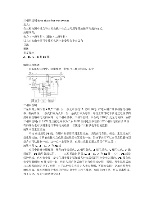
应用学科:电力(一级学科);通论(二级学科)以上内容由全国科学技术名词审定委员会审定公布目录概述重复接地A、B、C、N和PE线编辑本段概述在低压配电网中,输电线路一般采用三相四线制,其中三相四线制三条线路分别代表A,B,C三相,另一条是中性线N,亦即零线,在进入用户的单相输电线路中,有两条线,一条我们称为火线,另一条我们称为零线,零线正常情况下要通过电流以构成单相线路中电流的回路。
而三相系统中,三相平衡时,中性线(零线)是无电流的,故称三相四线制;在380V低压配电网中为了从380V线间电压中获得220V相间电压而设N线,有的场合也可以用来进行零序电流检测,以便进行三相供电平衡的监控。
编辑本段重复接地不论N线还是PE线,在用户侧都要采用重复接地,以提高可靠性。
但是,重复接地只是重复接地,它只能在接地点或靠近接地的位置接到一起,但绝不表明可以在任意位置特别是户内可以接到一起。
这一点一定要切记,也要注意你的朋友是否有所违反!!编辑本段A、B、C、N和PE线应用中最好使用标准、规范的导线颜色:A相用黄色,B相用绿色,C相用红色,N线用蓝色,PE线用黄绿双色。
三相五线制是指A、B、C、N和PE线,其中,PE线是保护地线,也叫安全线,是专门用于接到诸如设备外壳等保证用电安全之用的。
PE线在供电变压器侧和N线接到一起,但进入用户侧后绝不能当作零线使用,否则,发生混乱后就与三相四线制无异了。
但是,由于这种混乱容易让人丧失警惕,可能在实际中更加容易发生触电事故。
现在民用住宅供电已经规定要使用三相五线制,如果你的不是,可以要求整改。
为了安全,要斩钉截铁地要求!。

<Electrical and electronic technology>Chapter One: DC Circuit and analysis methodsThe basic concept : the composition and role of the circuit ; understand and master circuit current; voltage and electromotive force ; the physical meaning of electric power and energy ; understand the meaning of the voltage and electromotive force ; current reference direction ; understand and master the basic circuit element resistors; inductors; capacitors V - Ante ; as well as a voltage source including the constant voltage source ; the current source including the constant current source of the external characteristics ; understand circuit power of the three working status and characteristics ; understand the concept of electrical equipment components ratings ; and three modes of operation ; understand the concept of the potential ; understanding the relationship between the potential and voltage .Basic laws and theorems : mastering Kirchhoff's current and voltage law and Ohm's law and its applications ; with particular emphasis on Σ I = 0 and Σ U = significance 0:00 two sets of positive and negative numbers ; and Ohm's law in the sign significance. Analysis basis and method : Understanding resistance in series or parallel ; hybrid solution method to master the equivalentresistance of the resistor circuit ; as well as diversion; skilled application of pressure points formula ; master the method for determining the load circuit; circuit elements ; power supply ; control circuit power balance analysis ; master with branch current method ; the principle of superposition ; Thevenin theorem and power equivalent transformation methods such as analysis; calculation circuit ; grasp calculation circuit potential of each point . Chapter 2: sinusoidal AC circuitBasic concepts : understanding the three elements of a sinusoidal AC : amplitude; frequency and initial phase ; understand the concept of RMS and the phase difference ; grasp sine amount phasor notation ; master volume and conversion methods sinusoidal phase between the amount ; understanding sinusoidal instantaneous power AC circuits ; reactive power; apparent power concept ; master active power; power factor concept ; understand the concept of impedance ; grasp complex calculation methods ; master phasor diagram of the painting .Basic laws and theorems : Understand the basic laws of phasor form circuits ; as well as phasor form ohm theorem.Analysis basis and method : mastering a single parameter AC circuit voltage and current phasor relationship; that therelationship between size and phase relationships ; understand impedance in series or parallel ; hybrid solution method to master the equivalent impedance of the circuit ; as well as diversion; the partial pressure of the formula phasor type of skilled application ; master circuit judge load nature ; master method phasor method ; phasor diagram ; as well as calculating the phase relationship between the size of the relationship and the simple sinusoidal circuit ; grasp active power; reactive power and apparent power calculation methods ; to improve understanding of the inductive load power factor approach.Chapter 3 : Three-phase AC circuitBasic concepts: symmetric three-phase voltage to understand the concept of understanding the concept of the phase voltage ; phase current and line voltage and line current ; to understand the concept of three-phase symmetrical and asymmetrical loads understand the concept of a three-phase symmetry of the circuit; the negative voltage and current ; grasp the three-phase load connection method ; understand three-phase four -wire power supply circuit in the middle of the action ; understanding the three-phase circuit active power ; apparent power and reactive power concept of .Analysis basis and method : mastering phase symmetrical load Y connection and △ connection ; the line voltage and phase voltage and line current and phase current magnitude and phase relationships; and lines; calculate the phase voltages and currents ; master the three-phase unbalanced load when the Y connection and there is midline ; calculate the line current and neutral current ; grasp three-phase circuit active power; apparent power and reactive power calculations.Chapter 4: Common semiconductor devicesBasic concepts : understanding the formation and unidirectional conductive semiconductor basic knowledge and PN junction ; grasp diode voltage characteristics and unidirectional conductivity characteristics; to understand the main parameters and significance diodes ; master diode circuit symbol ; understanding silicon regulator the structure and main parameters of the regulator control circuit symbols ; understand the basic structure of the transistor and the current amplification; and the understanding of the characteristic curve of the transistor in the enlarged area ; and the cutoff characteristics of the saturation region ; the main parameters of the transistor understood master NPN type and PNP transistor circuit symbol .Analysis basis and method : the diode forward voltage withstand positive bias diode conduction withstand reverse voltage reverse bias diode cutoff . When subjected to reverse breakdown voltage regulator tube current limiting resistor under the action of the voltage across the regulator stable and unchanging applying a reverse voltage is greater than the stable voltage ; whether the person ; the regulator reverse cutoff ; If the regulator withstand the forward voltage regulator turns on with the diode same . Ideal diode and the ideal regulator : for idealized treatment that forward voltage is zero ; the reverse cutoff infinite resistance .Triode work in the enlarged area : emitter junction is forward biased voltage withstand ; collector junction withstand reverse bias voltage ;Transistors in saturation : the emitter junction is forward biased withstand voltage ; collector junction bear positive bias voltage ;Transistor in cutoff region : emitter junction withstand reverse bias voltage ; collector junction under reverse bias voltage ;Difficulties: including diodes and regulator circuit analysis ; transistor three working state judgment and the judgment of the transistor type ; polarity and materials.Chapter 5: Basic amplifier circuitBasic concepts : understanding the role of the composition of various common-emitter amplifier circuit part of the pole ; understanding zoom works; understanding the static and dynamic amplification circuit ; understand the role of quiescent operating point ; understanding amplifying circuit AC parameters: input resistance ; output resistance and the magnification of the significance.Analysis basis and method : direct access and communication pathways master painting ; grasp static analysis methods: estimation method and graphical method ; grasp the DC load line painting ; grasp the dynamic analysis methods: micro- computing small signal ac equivalent circuit parameters becomes law ; graphic method for qualitative analysis will ; stable quiescent operating point to understand the processes and principles ; understanding emitter 's basic characteristics and uses.Key elements: a fixed bias circuit ; voltage divider type amplifier circuit quiescent operating point of the three circuits emitter and slightly changed equivalent circuit. Will draw DC path and exchange accessChapter VI : Integrated Operational AmplifierBasic concepts : operational amplifier integrated graphics symbols and pins purposes ; negative feedback amplifier circuit and depth of negative feedback ; integrated operational amplifier ideal conditions and basic performance ; analysis of three basic op amp circuit ; integrated operational amplifier basic application Circuit ie : addition; subtraction ; integral and differential circuits ; consisting operational amplifier ; the main parameters ; proportional arithmetic circuit ; integrated operational amplifier applications ; model ideal conditions for integrated operational amplifier.Chapter 7: DC Power SupplyBasic concepts : Understanding DC power supply and the role of four areas : transformer ; rectifier ; filter and regulator ; understanding of single-phase half- wave bridge rectifier principle ; understand the principle of the filter circuit ; voltage regulator circuit. Understand the integrated voltage regulator applications.Analysis basis and method : Mastering half-wave ; bridge rectifier circuit calculating the average load voltage ; current; and the calculation of the average current rectifier diode and themaximum reverse voltage. Will draw half-wave ; wave bridge rectifier ; and the rectifier output load current; voltage polarity. Chapter 8: combinational logic circuitBasic concepts : logical relations ; and logic ; or logic; non-logical ; there is a corresponding basic gates ; and doors; or doors and NAND gate . Combination gate circuit ; a NAND gate ; NOR gate ; NOR gate ; three-state gate ; with the XOR gates and OR gates and the like. Should have a gate symbols; logic and logical expressions. Logical formula logic algebra is important to simplify the formula logical relationship should memorize and master simple formulaic approach .Analysis basis and method : combinational logic analysis and design is the focus of this chapter ; in particular; is a combination of logical analysis ; master steps.Difficulty: logical expression simplification and combinational logic circuit designChapter IX : sequential logic circuitsBasic concepts : basic RS flip-flop ; synchronous RS flip-flop logic symbols and logic functions ; JK flip-flop and D flip-flop ; is to learn the focus of this chapter. After the bistable ; CP pulseleading edge trigger and the trigger edge ; the difference between the symbols . Registers and counters should have analytical methods and points.Analytical basis and Methods: trigger -based ; to find CP relationship between each trigger to determine the frontier or back porch ; painting the output waveform ; identify the key points of transition until the next pulse occurs .Difficulty: analysis of synchronous counter。

239AMC系列可编程智能电测表AMC series Programmable Intelligent Electric Parameter Meters——三相电流、电压部分Three phase current,Three phase voltage Power(AI3、AV3)(A13.AV3)安装使用说明书V1.2Installation and operation instruction V1.2安科瑞电气股份有限公司Acrel Co.,Ltd申明DECLARATION版权所有,未经本公司之书面许可,此手册中任何段落,章节内容均不得被摘抄、拷贝或以任何形式复制、传播,否则一切后果由违者自负。
本公司保留一切法律权利。
No part of this publication may be reproduced,stored in a retrieval System,or transmitted in any form by any means,electronic,mechanical photocopying,recording,or otherwise without prior permission of Acrel.All rights reserved.本公司保留对手册所描述之产品规格进行修改的权利,恕不另行通知。
订货前,请垂询当地代理商以获悉本产品的最新规格。
目录CONTENTS1.概述General (1)2.产品型号规格Type and specification of products (1)3.技术参数Technical parameters (2)4.安装指南Installation guide (4)4.1外形及安装尺寸Outline overall and installing dimensions (4)4.2仪表及开孔示意图Instrument and cut out sketch map (4)4.3安装示意图Installation sketch map (4)4.4安装说明Installation instructions (4)4.5端子排列及接线Terminal arranging and wiring (5)4.6注意事项Notice (6)4.7典型应用Typical application (9)5.使用指南Operating guide (10)5.1按键Key press (10)5.2菜单符号及意义Menu symbol and meaning (11)5.3编程流程Programming flow (13)5.4功能设置与使用Function setting and using (16)6.通讯指南Communication guide (19)6.1概述General (19)6.2协议Protocol (19)6.3错误校验的方法Method of error-checking (19)6.4三相表通讯参量地址表Communication parameter address table (22)6.5通讯应用Communication application (24)1.概述GeneralAMC系列可编程智能三相电流、电压表,采用交流采样技术,可直接测量三相电网中的电流和电压。

【词汇】电阻resistance;电流current;电压voltage;电容capacitance;电感inductance;电感特性exhibit inductance;频率frequency;波形waveform;绝缘体insulator;导体conductor;阻值resist;能力,性能capability;耗散dissipate;容纳accommodate;电容器capacitor;电容capacitance;电感器inductor;共振,谐振resonate;发射器emitter;整流器rectifier;波长wavelength;原子atom;质子proton;电荷,负荷charge;吸引attraction;排斥repulsion;交流发电机alternator;发电机generator;势的,位的potential终端terminal;极性polarity;正弦sine;正弦波sinewave;;周期cycle;三相threephase;偏移量offset;;电枢armature;磁场magnetic field;顶点peak;峰值peakvalue;电路ciruit;负荷,负载load;开关,电闸,转换switch;示意性的schematic;计算,考虑calculate;分子numerator;转化的invert;支流branch;混合物compound;相等的equivalent;方法method;刷新redraw;二极管diode;晶体管transistor;半导体semiconductor;制作fabricate;晶体crystal;结合物bond;四面体tetrahedron;本质的intrinsic;杂物,混杂物impurity;中等的moderate;极性polarity;交感interaction;损耗depletion;相反reverse;真空vacuum;泄漏leakage;数字的numerical;十进制decimal;阿拉伯数字digit;权重weight;幂power;二进制binary;位bit;乘multiply;余数remainder;综合integration;双极的bipolar;变极器inverter;便携式电脑laptop;描述depict;瞬间的momentary;逻辑门gate;图表的diagrammatic;方向,方位orientation;芯片chip;多路器multiplexer;定理theorem;搅拌机mixer;向量vector;摩擦力friction;扭矩torque;乘积product;半径,范围radius;杠杆lever;旋转revolution;惯性inertia;补偿compensate;功work;【短语】工业总线industrial bus;电压差voltage difference; 电压降voltage drop;串联电路series circuit; 并联电路parallel circuit; ;换向开关inverter switch;开关输入量discrete input; 正电荷positive charge;负电荷negative charge; 正向positive direction;负向negative direction;反向opposite direction;三相three-phase;磁场magnetic field;交流变量alternating current component;超时over time; 电场electric field; 峰值peak value;三角函数trigonometric function;均方根root-mean-square;等值电路equal value resistors;复合电路compound circuits; 数字转换conversion of number; 可编程控制器programmable controller;电能electrical energy;机械能mechanical energy;惯性定律law of inertia;电枢磁场armature field;右手法则right-hand rule;采样间隔sampling interval;模拟信号analog signal;数字信号digital signal;模拟量输入analog input;接近开关proximity switch;有功功率active power;放大区amplifier region;异步电动机asynchronous machine;开关量输出discrete output;三相交流电three-phase;有源滤波器active filter;在—之间between and;另一方面on the other hand;利用take advantage of;包围close in;由---组成be formed by;考虑take into account;支路by-pass;中性状态neutral state;挤出去force out;自由电子free electron;电流current flow;图示graphic representation;正弦波sine wave;;;与—有关be referable to;;最小公倍数lowest common multiple;复合电路compound circuits;并联分支parallel branch;物理类型physics types;碳族carbon family;三维的3-dimensional;外层电子outer electron;元素周期表periodic table;PN结PNjunction;N区Nregion;数字系统number system;数字值numerical value;十进制系统decimal system;二进制系统binary system;指轮开关thumb wheel switch;;超大规模集成电路very large scale integration;;真值表truth table;牵引电阻pull-up resistor;;米每秒meters per second;角速度angular speed;外力external force;转动惯量moment of inertia;蒸汽机steam engine;绕—而走walk around;欧姆定律Ohm’s law;色条代码color chart codes;国家军用规格和标准National Military specification and standard;检查和维修inspection maintenance;保修条款;limited warranty policy;原子中性状态neutral state of an atom;电中性electrically neutral;交流正弦波ACsine wave;三相交流电three-phase AC power;瞬时电压instantaneons voltage;有效值effective value;简单电路simple electric circuit;数字电路digital circuit elememts;人工布线manual routing;自动布线auto routing;静力net force;线速度linear speed;角速度angular speed;加速度acceleration;【缩写】DC(Direct Current)直流电;BCD(Binary-Coded Decimal)二进制编码的十进制;CMOS(comliementary metal oxide semiconduct)互补金属氧化物半导体;AC(Alternating Current)交流电;RPM(revolutions per minute)转/分;RF(Radio Frequency)射频,无线电频率;BCD(Binary Coded Decimal)二进制编码的十进制;CEMF(CounterElectroMotiveForce)反电动势;PID(proportional integral differential)比例积分微分;PLC (programmable logic controller)可编程逻辑控制器;ADC(analog to digital converter)·模拟/数字转换器;【翻译】1.Resistors are used to control voltagesand currents:电阻器被用于控制电压与电流2.Resistors are components that have a predetermined resistance.Resistance determines how much current will flow through a component.电阻器是预先设定好的元件。
并联型APF补偿容性非线性负载不稳定机理研究李鹏;蒋晓明;黄俊华;张涛【摘要】Instability can occur when a parallel active power filter whose reference current is deduced based on load current detection is applied to compensate capacitive nonlinearity load. The root cause of instability is the mismatch and the mutual influence of input and output impedance in cascade system. The mathematical model of parallel active power filter which is applied to compensate capacitive nonlinearity load is primarily built for the problem in this paper, and the impedance characteristic of input and output part in cascade system is analyzed based on the Middlebrook impedance analysis theory, the root instability cause is discussed by the stability criterion in cascade system, finally, the simulation and experimental results validate the correctness of the theoretical analysis.%基于负载电流检测方式的并联型有源电力滤波器补偿容性非线性负载时会发生不稳定的现象,其根本原因在于整个级联系统输入输出级阻抗不匹配,存在相互影响。
三相四线制有源电力滤波器指定次数谐波控制策略李彩林;惠梓舟;蔡儒军;周志林【摘要】针对三相四线制低压配电网不平衡非线性负载的电能质量问题,提出采用矢量谐振控制器对电容分离型有源电力滤波器(Active Power Filter,APF)进行指定次数谐波控制方案.在αβγ坐标系下对电容分离型APF进行建模,省去了在dq坐标系下的电流交叉解耦环节.比例谐振控制器应用在APF闭环控制系统时,存在各次谐振点附近谐振尖峰影响闭环控制系统稳定性和补偿精度的问题,采用矢量谐振控制器实现指定次数谐波跟踪控制,其分子零点与控制对象的极点抵消,实现控制系统降阶,提高了控制性能.仿真结果表明,所提控制方法在针对指定次数谐波补偿方面有着良好效果,其三相不平衡被抑制,直流侧电容电压得到均衡控制,证明了所提方法有效性.%In view of the power quality of unbalanced nonlinear load for the three-phase four wire low voltage distribu-tion network, the control scheme of using vector proportional resonant controller to suppress specific harmonic is pro-posed.The split-capacitor-type active power filter ( APF) mathematical model is established based onαβγcoordinate system, and current cross decoupling link under dq coordinate system is omitted.The proportional resonant controller is applied in the closed-loop control system of APF, and the resonance peak near the resonance point can affect the stability and compensation precision.In this paper, the vector resonance controller is adopted to suppress specific har-monic tracking control, and the zero point of the controller can molecule the pole of control object, thus the three-phase unbalanced order of control system is reduced to improve the control performance, and the DC side capacitorvoltage is also controlled in balance.The simulation results verify the validity of the proposed method.【期刊名称】《电测与仪表》【年(卷),期】2017(054)003【总页数】6页(P83-88)【关键词】电容分离型;有源电力滤波器;不平衡;指定次数谐波控制;矢量谐振控制器【作者】李彩林;惠梓舟;蔡儒军;周志林【作者单位】桂林电子科技大学机电工程学院,广西桂林541004;桂林电子科技大学机电工程学院,广西桂林541004;桂林电子科技大学机电工程学院,广西桂林541004;桂林电子科技大学机电工程学院,广西桂林541004【正文语种】中文【中图分类】TM7140 引言随着电力电子技术的不断发展,大量非线性负载被广泛运用于低压配电网中,不平衡、谐波和无功问题日益突出,同时由于中性线的存在,零序电流的补偿也成了一个研究的热点[1]。
A Three-Phase Four-Wire Power Filter Comprisinga Three-Phase Three-Wire Active PowerFilter and a Zig–Zag TransformerHurng-Liahng Jou,Member,IEEE,Kuen-Der Wu,Jinn-Chang Wu,and Wen-Jung ChiangAbstract—Active powerfilters(APFs)have been developed to solve the problems of harmonic suppression and reactive power compensation simultaneously.In this paper,a three-phase four-wire powerfilter comprising a three-phase three-wire APF and a Zig–Zag transformer is developed.A hardware prototype is imple-mented and tested to verify the performance of the proposed power filter under various ideal and non-ideal power conditions.Exper-imental results show that this three-phase four-wire powerfilter has the desired performance under limited zero sequence utility voltage.Index Terms—Active powerfilter(APF),harmonic,Zig–Zag transformer.I.I NTRODUCTIONT HREE-PHASE four-wire distribution power systems have been widely used in office buildings,commercial com-plexes,manufacturing facilities,etc.to supply low-level voltage. The typical loads connected to the three-phase four-wire distri-bution power system may be computer related facilities,office automatic machines,adjustable speed drives,lighting ballasts and other power electronic related facilities.These loads may be either single-phase or three-phase loads.Most of these loads have a nonlinear input characteristic,which may create prob-lems of high input current harmonics and serious zero-sequence current.The neutral conductor of the three-phase four-wire distribution power system is the current path for zero-sequence current.The input current of single-phase nonlinear load contains different harmonic components,and some of these harmonic components may result in a significant zero-sequence current.Furthermore,the single-phase loads of three-phases may be distributed unequally,which results in serious load unbalance and evident zero-sequence fundamental component. Because both the zero-sequence harmonic component and the zero-sequence fundamental component of unbalanced load currentflow into the neutral conductor,it may result in the overload of neutral conductor of the three-phase four-wire distribution power system.Survey results across computer sitesManuscript received September11,2006;revised July18,2007.This work was supported by the National Sciences Council of Taiwan,R.O.C.,under Con-tracts NSC93-2213-E-151-019and NSC94-2213-E-151-016.Recommended for publication by Associate Editor H.D.Mouton.H.-L.Jou,K.-D.Wu,and W.-J.Chiang are with the Department of Electrical Engineering,National Kaohsiung University of Applied Sciences,Kaohsiung 80778,Taiwan,R.O.C.(e-mail:hljou@.tw).J.-C.Wu is with the Department of Microelectronics Engineering,National Kaohsiung Marine University,Nanzih81143,Taiwan,R.O.C.Digital Object Identifier10.1109/TPEL.2007.911779in the U.S.have shown that22.6%of the sites have neutral currents exceeding the full-load phase currents[1],which may result in an overload accident of the neutral conductor. Thus,the three-phase four-wire distribution power systems have the problems of harmonic pollution,load unbalance and overload of neutral conductor.The conventional methods to solve the problems of the three-phase four-wire distribution power system are:1)a higher power rating distribution transformer and neu-tral conductor are used to prevent overload.However,this method cannot solve the harmonic problem;2)three single-phase passive powerfilters are installed[2].However,this method has a hidden risk of series/parallel resonance;3)a Zig–Zag transformer is applied to suppress the neu-tral current[3],[4].However,this method can solve the problem of neutral conductor but it cannot solve the har-monic problem;4)a three-phase four-wire active powerfilter(APF)is in-stalled[5]–[9].This method can solve the problems of har-monic pollution,load unbalance and overload of the neu-tral conductor.Thus,it can be found that only the three-phase four-wire APF can effectively solve the problems of harmonic pollution,load unbalance and overload of neu-tral conductor in a three-phase four-wire distribution power system.Hence,the performance of three-phase four-wire APF is better than other conventional methods.However, the cost is higher than other methods. Conventionally,a three-phase three-wire APF,comprising a three-arm power converter or a two-arm power converter with split capacitors,is used to compensate for the harmonic cur-rents in the three-phase three-wire distribution power system[10]–[12].In contrast,a three-phase four-wire APF,comprisinga four-arm power converter or a three-arm power converter with split capacitors,is used to compensate for the harmonic cur-rents in the three-phase four-wire distribution power system. If a three-phase APF can be applied in both the three-phase three-wire and three-phase four-wire distribution power system, manufacturers only need to develop the three-phase three-wire APF.Hence,they can save time and reduce the cost for the research and development of three-phase four-wire APFs.In this paper,a three-phase four-wire powerfilter comprising a three-phase three-wire APF and a Zig–Zag transformer is pro-posed.The advantage of this configuration is that the develop-ment of three-phase four-wire APF technology is no longer re-quired.In addition,the power rating of power converter can be0885-8993/$25.00©2007IEEEFig.1.System configuration of the proposed powerfilter is consisted of a three-phase APF and a Zig–Zag transformer.reduced while comparing with three-phase four-wire APF.A hardware prototype is implemented and tested to verify the per-formance of this three-phase four-wire powerfilter.II.B ASIC O PERATION P RINCIPLEFig.1shows the system configuration of the developed three-phase four-wire powerfilter.The proposed powerfilter com-prises a three-phase three-wire APF and a Zig–Zag transformer. The Zig–Zag transformer acts as a path for zero-sequence com-ponents of load current.The main purpose of the three-phase three-wire APF performs as a harmonicfilter tofilter the positive and negative sequences harmonic current components caused by the load,and this APF also forces the utility current to be si-multaneously balanced and in phase with the positive-sequence components of utility voltage.Because the zero-sequence com-ponents of load currents willflow into the Zig–Zag transformer, and the APF is not required to compensate the zero-sequence components of load currents,thus the power rating of power converter can be reduced effectively.The power rating of power converter saving in the proposed three-phase four-wire power filter is determined by the zero-sequence components of load currents.III.T HREE-P HASE T HREE-W IRE A CTIVE P OWER F ILTER The purpose of an APF is to compensate for the reactive power and cancel the harmonic components caused by the nonlinear loads simultaneously.In other words,the APF is used to force the utility current to be a sinusoidal waveform and to be in phase with the utility voltage when the utility is balanced.Hence,the control object of the proposed APF is the utility current directly [13],[14].The salient point of this method is that the command in the controller is the utility current and not the converter output current,as used in most other APF control methods[5]–[8].For a three-phase four-wire system,the positive-sequence compo-nents of three-phase phase voltages are assumedas(1)(2)(3)Since the Zig–Zag transformer is connected between the APFand the load,it can compensate for the zero-sequence compo-nents of load current.The three-phase load currents for the APFonly contain positive-sequence and negative-sequence compo-nents and can be represented in the Fourier series formas(4)(5)(6)Because the APF is adapted to compensate the reactive powerand suppress the harmonic currents,the desired three-phaseutility currents after compensating are sinusoidal and balanced.Hence,the desired utility currents after compensating containonly the positive-sequence fundamental components and canbe representedas(7)(8)(9)where is the amplitude of the utility currents.The basic concept of this method is to force the three-phaseutility currents,shown as(7)–(9),to be balanced and sinusoidalwithout taking the load characteristic into consideration.Hence,the waveforms and phases of the desired three-phase utility cur-rents are pre-known,and the only unknown parameter is theiramplitude.The amplitude of the three-phase utility currents canbe determined by power balancing among the utility,the APFand the load.The dc capacitor on the dc side of power converteracts as an energy buffer and creates a stable dc voltage for thepower converter in the steady-state condition.If the real powersupplied from the utility cannot satisfy the demanded real powerof load,the difference of real power must be injected into or sup-plied from the dc capacitor.The difference of real power willresult in the voltage variation of dc capacitor.Since the utilitypower factor is desired to be close to unity after compensationby the proposed powerfilter,the difference of real power can berepresentedas(10)where is the demanded real power of load.If is nega-tive,it means that the supplied real power is smaller than thedemanded real power,so the voltage of the dc capacitor will bereduced.On the contrary,if is positive,it means that the sup-plied real power is larger than the demanded real power,so thevoltage of the dc capacitor will be increased.Hence the differ-ence of realpower must be controlled to be zero in the steady state.From(10),it can be found that the amplitude of the utilityvoltages and demanded real power of load are un-controllable,and then the difference of real power can only be controlled byFig.2.Control block diagram of this three-phase three-wire APF.controlling the amplitude of the utility currents.If the dc capac-itor voltage is below the steady-state value,the amplitude of the utility currents must be enlarged to increase the difference of real power.On the contrary,the amplitude of the utility currents must be decreased to reduce the difference of real power when the dc capacitor voltage is over the steady-state value.Therefore,the amplitude of the utility currents can be obtained by control-ling the amplitude of dc capacitor voltage.The control circuit can only be used to determine the amplitude of utility currents.Moreover,it can avoid the matching adjustment of the current sensors used for detecting the load currents and the APF output currents in the conventional APF because the current sensors used in this APF are only to detect the three-phase utility cur-rents.This simpli fies the control circuit and reduces the number of current sensors [13],[14].Fig.2shows the control block diagram of this APF.The above paragraph shows that the control objects are the utility currents,and so the reference signals are the desired utility cur-rents.The control circuit first calculates the reference signals,and then the reference signals and the utility currents are sent to the current controller to generate the switching signals for the power electronic devices of power converter to force the utility currents to follow the reference signals.The reference signals are three sinusoidal signals with controllable amplitude.The dc capacitor voltage is detected and subtracted from the setting dc voltage,and then the error is fed toa–controller.The set-ting dc voltage is the desired steady-state value of dc capacitor voltage.The outputof–controller is the amplitude of refer-ence signals.The utility voltages are often unbalanced in actual distribution power systems.In order to obtain three-phase bal-ance of utility currents after compensating,the utility voltages must be sent to a positive-sequence detection circuit.The unbal-anced utility voltages can be divided into zero-sequence,pos-itive-sequence and negative-sequence components by the fol-lowing equation[15]:(11)Fig.3.Zero-sequence equivalent circuit.where,and are zero-sequence,positive-sequence and negative-sequence components of the utility voltages,re-spectively,and the operator ais:1120(12)Equation (11)shows that the positive-sequence component of the utility voltage can be representedas:(13)Hence,two 120phase shift circuits and a summing circuit are used to con figure the positive-sequence detection circuit.The output of positive-sequence detection circuit is sent to the bal-anced sinusoidal signal generator to generate the three-phase balanced sinusoidal signals.The balanced sinusoidal signal gen-erator contains two 120phase shift circuits to obtain the phase b and c signals and three band-pass filters to filter out the har-monics.The outputs of the balanced sinusoidal signal generator andthe–controller are sent to multipliers.The products of multipliers are the desired three-phase utility currents.The fixed frequency current-mode control is used in this paper.Three cur-rent sensors are used to detect the practical utility currents di-rectly,and then the desired three-phase utility currents and the practical utility currents are sent to a three-phase current con-troller.Finally,the output signals of the current controller are sent to the pulse-width modulator to generate the driving sig-nals for the power electronic devices of power converter.If the practical utility currents can trace the desired utility currents,then the expected performance of APF can be obtained.IV .Z IG –Z AG T RANSFORMERThe Zig –Zag transformer is connected in parallel to the load for filtering the zero-sequence components of the load currents [4].As seen in Fig.1,the Zig –Zag transformer consists of three transformers with the turn ratio of 1:1,and the currents flowing through the utility side of these three transformers are equal.Hence,the Zig –Zag transformer can be regarded as open-circuit for the positive-sequence and the negative-se-quence currents.Then,the current flowing through the Zig –Zag transformer is only the zero-sequence component.The zero-se-quence equivalent circuit of the system contains the Zig –Zag transformer and the zero-sequence component of nonlinear load can be expressed as Fig.3.To simplify the analysis,the zero-sequence component of nonlinear load is regarded as azero-sequence currentsource.Hence,it consists of two zero-sequence powersources,and ,where is a zero-sequence voltage of the utility voltage caused by the un-balanced utility voltage.In Fig.3,,and are thezero-sequence impedance of the utility,Zig–Zag transformer and the zero-sequence impedance of the neutral conductor between the Zig–Zag transformer and the utility,respectively. Since the Zig–Zag transformer is expected to be located as near as possible to the load,the zero-sequence impedance of the neutral conductor between the Zig–Zag transformer and the load can be neglected.From(11),the zero-sequence of utility voltage can be ex-pressedas(14)The effects oftheand to the utility side neutral currentafter using the Zig–Zag transformer can be analyzed by usingthe superposition theory.To consider the effect ofthe,themust be assumed to be a short circuit in Fig.3.Then,theutility side neutralcurrent causedby can be expressedas(15)Equation(15)indicates that the magnitude of the neutral currentcausedby will be reduced after applying the Zig–Zag trans-former.To consider the effect ofthe,the is assumedto be an open circuit in Fig.3.Then,the neutral current of theutility side causedby can be expressedas(16)Equation(16)shows that the Zig–Zag transformer supplies apath for the zero-sequence currentflowing between the utilityand the Zig–Zag transformer.However,the impedance of theutility system,the Zig–Zag transformer and the neutral con-ductor are very small in most the three-phase four-wire distribu-tion power systems.Hence,the Zig–Zag transformer will drawthe zero-sequence current from the utility when the utility con-tains zero-sequence voltages.To reduce the neutral current ofutility side furthermore after applying the Zig–Zag transformer,it is suggested to insert aninductor in the neutral conductorof the utility side in order to enlarge theimpedance asshown in Fig.1.Therefore,the practical neutral current of utilityside can be obtained by adding(15)and(16),and this can be ex-pressedas(17)Equation(17)shows that thelarger is thesmaller willbe.This means that the installation of Zig–Zag transformer mustbe as near the load as possible or it will be necessary to in-sert an externalinductor to increasethe.However,the insertedinductor may result in the voltage variationor rising up the neutral voltage of the load side,and this phe-nomenon may cause abnormal operation of the electric facilitiesin the load side.Hence,the selection of insertedinductormust take the practical zero-sequence component of the utilityvoltage and the limitation for the related electrical regulationsinto consideration.TABLE IP ARAMETERS OF P OWER CONVERTERFig.4.Experimental results of the proposed powerfilter under the ideal con-dition:(a)A phase load current,(b)B phase load current,(c)C phase loadcurrent,and(d)neutral current of the loadside.Fig.5.Experimental results of this APF under the ideal condition:(a)A phaseutility current,(b)B phase utility current,(c)C phase utility current,and(d)neutral current of the utility side.V.E XPERIMENTAL R ESULTSA prototype is developed to verify the performance of the pro-posed powerfilter under different utility and load conditions,where the utility system is220V and60Hz.The parametersof power converter used in the developed three-phase four-wirepowerfilter are shown in Table I.Aninductor with1mHis inserted between the Zig–Zag transformer and the utility.The can prevent the zero-sequence current causingbyflowing into the neutral conductor of the utility side.The loadused in the following test is the single-phase rectifier load,con-sisted of a rectifier,a dc capacitor and a resistor,and it is con-nected between the phase and neutral of three-phase four-wireutility.A.Ideal ConditionsThe experimental results of three-phase four-wire APF underthe ideal utility voltages and the balanced loads are shown inFigs.4and5.These results show that the waveforms of theFig.6.Experimental results of the proposed power filter under the condition of single-phase load current:(a)A phase load current,(b)B phase load current,(c)C phase load current,and (d)neutral current of the loadside.Fig.7.Experimental result of the proposed power filter under the condition of single-phase load current,(a)A phase utility current,(b)B phase utility current,(c)C phase utility current,and (d)neutral current of the utility side.utility currents are sinusoidal and synchronous with the utility voltages after compensating by the three-phase four-wire APF.The total harmonic distortion (THD)of load is 61.3%,and it is reduced to 3.8%in the utility current.The neutral current is attenuated from 11.94A to less than 0.85A.Hence,the exper-imental results show that the proposed power filter has the per-formance of harmonic current suppression,reactive power com-pensation and neutral current attenuation in the ideal condition.B.Load UnbalanceIn practical three-phase four-wire industry distribution power systems,the condition of single-phase load also may occur,which can be regarded as the most serious unbalanced load.Figs.6and 7show the experimental results under this condi-tion.These experimental results indicate that the waveforms of utility currents are sinusoidal and synchronous with the utility voltages after compensating.The neutral current is attenuated from 7.36A to less than 0.52A.Hence,these results show that the proposed power filter has the performance of harmonic current suppression,reactive power compensation and neutral current attenuation,and it also balances the utility currents under the condition of the single-phaseload.Fig.8.Experimental results of the proposed power filter under the condition of amplitude unbalance of the utility voltages (the inserted inductor is 1mH):(a)A phase utility voltage,(b)B phase utility voltage,and (c)C phase utilityvoltage.Fig.9.Experimental results of the proposed power filter under the condition of amplitude unbalance of the utility voltages(the inserted inductor is 1mH):(a)A phase load current,(b)B phase load current,(c)C phase load current,and (d)neutral current of the loadside.Fig.10.Experimental result of the proposed power filter under the condition of amplitude unbalance of the utility voltages(the inserted inductor is 1mH):(a)A phase utility current,(b)B phase utility current,(c)C phase utility current,and (d)neutral current of the utility side.C.Unbalance of the Utility VoltageThe amplitude of three-phase voltages is the same in ideal utility condition.However,the amplitude unbalance occurs frequently in practical three-phase four-wire distribution power system.Figs.8–11show the experimental results under thisFig.11.Experimental results of the proposed power filter under the condition of amplitude unbalance of the utility voltages(the inserted inductor is 5mH):(a)A phase utility current,(b)B phase utility current,(c)C phase utility current,and (d)neutral current of the utility side.condition.The unbalanced three phase voltages are 170V ,180V ,and 180V.According to the above analysis,the un-balanced utility voltage will result in a zero-sequence voltage,and this zero-sequence voltage will generate a fundamental zero-sequence current flowing through the three-phase utility conductors,Zig –Zag transformer and utility neutral con-ductor.Since the three-phase three-wire APF cannot generate zero-sequence compensation current,the attenuation of neu-tral current is only dependent on the inserted inductor.Theinsertedinductoris 1mH in Fig.10,and that is 5mH in Fig.11.Fig.10shows that the neutral current is attenuated from 12.75A to less than 4.334A.As seen in Fig.11,the neutral current is attenuated from 12.2A to less than 1.6A.Due to the three-phase utility currents contain the zero-sequence component in this case,the practical utility currents cannot be as expected.This may result in the saturation of three-phase current controller in the three-phase three-wire APF.Hence,the harmonic suppression performance of the utility currents after compensation in Fig.10is not very good,and this is improved in Fig.11by using a larger inserted inductor to reduce the zero-sequence component in the utility currents.This means that the zero-sequence current of the utility is smaller in Fig.11than that in Fig.10,and the utility currents are closer to being sinusoidal if a larger inserted inductor is used.Fortunately,the percent voltage unbalance of the utility voltage in the distri-bution power system is limited below 5%,so the degradation of harmonic suppression performance is not serious under the unbalance of the utility voltages.D.Distortion of the Utility VoltageWaveforms of the utility voltage are frequently distorted due to the wide use of nonlinear loads.Figs.12–15show the exper-imental results under this condition.The THD of utility voltage is 16.4%,and it contains odd (third,fifth,etc.)harmonic com-ponents.The insertedinductoris 1mH in Fig.14,and that is 5mH in Fig.15.Fig.14shows that the neutral cur-rent is attenuated from 11.62A to less than 2.1A.Since the utility voltage contains zero-sequence voltage (third harmonic component),it will generate a zero-sequence current flowing through the three-phase utility conductors,Zig –ZagtransformerFig.12.Experimental results of the proposed power filter under the condition of the distorted utility voltages(the inserted inductor is 1mH):(a)A phase utility voltage,(b)B phase utility voltage,and (c)C phase utilityvoltage.Fig.13.Experimental results of the proposed power filter under the condition of the distorted utility voltages (the inserted inductor is 1mH):(a)A phase load current,(b)B phase load current,(c)C phase load current,and (d)neutral current of the loadside.Fig.14.Experimental results of the proposed power filter under the condition of the distorted utility voltages (the inserted inductor is 1mH):(a)A phase utility current,(b)B phase utility current,(c)C phase utility current,and (d)neutral current of the utility side.and utility neutral conductor.As seen in Fig.15,the neutral cur-rent is attenuated from 11.6A to less than 0.7A by using a larger inserted inductor.This means that the zero-sequence cur-rent of the utility is smaller in Fig.15than that in Fig.14,and the utility currents are closer to being sinusoidal if a larger insertedFig.15.Experimental results of the proposed power filter under the condition of the distorted utility voltages(the inserted inductor is 5mH):(a)A phase utility current,(b)B phase utility current,(c)C phase utility current,and (d)neutral current of the utilityside.Fig.16.Experimental results for the transient performance of the proposed power filter(APF OFF !ON,Zig –Zag ON):(a)phase utility voltage,(b)phase utility current,(c)phase load current,and (d)neutral current of the utility side.inductor is used.In practice,the percent voltage unbalance of the utility voltage in the distribution power system is expected to below 5%,so the degradation of harmonic suppression per-formance is not serious under the little distortion of the utility voltages.E.TransientFig.16shows the transient performance of the proposed power filter under the condition that the Zig –Zag is connected and the APF is from turning off to turning on.As seen in Fig.16,the utility current is distorted before applying the APF;and the utility current is compensated to be sinusoidal after ap-plying the proposed power filter.Furthermore,it can be found that the developed power filter has a good transient response under this condition.Fig.17shows the experiment results for the transient performance of the proposed power filter while three-phase three-wire APF is operated and the Zig –Zag trans-former is from turning off to turning on.Fig.17(b)shows that the utility current contains the zero-sequence current before the Zig –Zag transformer is turned on,and the utility current will be compensated to be sinusoidal after the Zig –Zag transformer is turned on.As seen in Fig.17(b),the load current is increased at the transient of applying the Zig –Zag transformer.ThiscanFig.17.Experimental results for the transient performance of the proposed power filter(APF ON,Zig –Zag OFF !ON):(a)phase utility voltage,(b)phase utility current,(c)phase load current,and (d)neutral current of the utilityside.Fig.18.Experimental results of this APF under the condition of increasing nonlinear load:(a)phase utility voltage,(b)phase utility current,(c)phase load current,and (d)neutral current of the utility side.be explained as that the disappearance of the zero-sequence component in the utility current will be resulted in the increased utility voltage at this instant.This small voltage rising of the utility voltage will charge the dc capacitor via the recti fier,so that the load current is increased at the instant of the voltage rising.After the transient,the load current will decay to a new stable value as the dc voltage is reached to a higher stable value.Fig.17(d)shows that the neutral current of the utility side contains the zero-sequence current before the Zig –Zag transformer is turned on,and the neutral current of the utility side will be quickly and effectively decayed after applying the Zig –Zag transformer.Fig.18shows the experiment results for transient performance of the proposed power filter under the condition of increasing the nonlinear load.As seen in Fig.18,the load current is increased at the transient of increasing nonlinear loads and then decrease to the new steady state value.This figure shows that the proposed power filter can respond very fast,and the experimental results above verify that the proposed power filter has an excellent transient performance.VI.C ONCLUSIONThe three-phase four-wire distribution power system faces not only the problem of harmonic pollution but also the problem of the overload current in the neutral conductor.This paper。