EEMUA标准铜镍管及附件参数Copper Nickel
- 格式:pdf
- 大小:1016.54 KB
- 文档页数:47
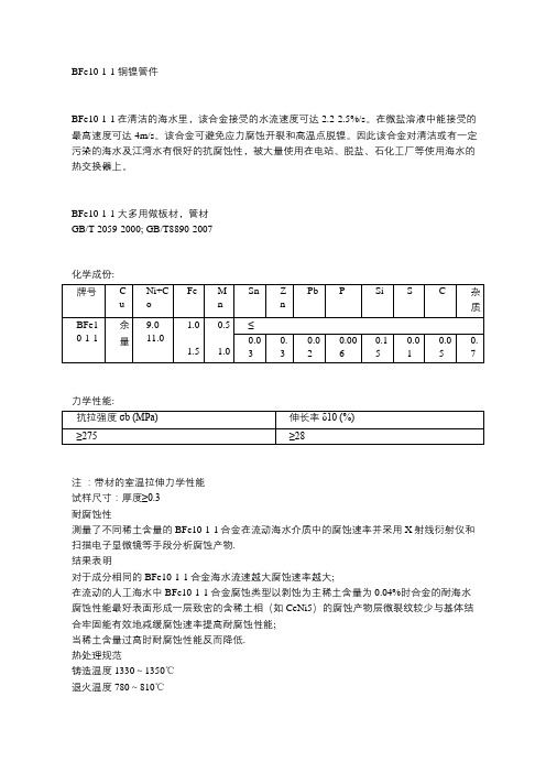
BFe10-1-1 铜镍管件
BFe10-1-1在清洁的海水里,该合金接受的水流速度可达2.2-2.5%/s。
在微盐溶液中能接受的最高速度可达4m/s。
该合金可避免应力腐蚀开裂和高温点脱镍。
因此该合金对清洁或有一定污染的海水及江湾水有很好的抗腐蚀性,被大量使用在电站、脱盐、石化工厂等使用海水的热交换器上。
BFe10-1-1 大多用做板材,管材
GB/T 2059-2000; GB/T8890-2007
化学成份:
力学性能:
注:带材的室温拉伸力学性能
试样尺寸:厚度≥0.3
耐腐蚀性
测量了不同稀土含量的BFe10-1-1合金在流动海水介质中的腐蚀速率并采用X射线衍射仪和扫描电子显微镜等手段分析腐蚀产物.
结果表明
对于成分相同的BFe10-1-1合金海水流速越大腐蚀速率越大;
在流动的人工海水中BFe10-1-1合金腐蚀类型以剥蚀为主稀土含量为0.04%时合金的耐海水腐蚀性能最好表面形成一层致密的含稀土相(如CeNi5)的腐蚀产物层微裂纹较少与基体结合牢固能有效地减缓腐蚀速率提高耐腐蚀性能;
当稀土含量过高时耐腐蚀性能反而降低.
热处理规范
铸造温度1330~1350℃
退火温度780~810℃
挤压热加工温度900~960℃
消除内应力的低温退火温度250~300℃。

镍和镍合金无缝钢管的一般要求标准SB829(除了已经强制认证的,其它与ASTM规范B 829 - 99一致)1. 范围1.1 该规格(不包括第5节和第4节中的规格)强制性按照以下ASTM镍和镍合金,无缝钢管标准来要求的各种规格。
规格ASTM 标示无缝镍钢管B161 冷凝器和热交换器的镍和镍合金无缝钢管B163 镍铜合金(UNS N04400)无缝钢管B165 镍铬铁合金(UNS N06600,N06601,N06690)无缝钢管B167 镍铁铬合金无缝钢管B407 镍铁铬钼铜合金(UNS N08825 ,N08221)无缝钢管B423 镍铬钼钶合金(UNS N06625)无缝钢管B444 钼钨合金(UNS N06102)无缝钢管B445 镍铁铬硅合金(UNS N08330 和UNS N08332)无缝钢管B535 铜铍合金锻件和挤压件B570 无缝镍和镍钴合金管B622 UNS N08028无缝钢管B668 UNS N8904,UNS N08925 ,UNS N08926无缝钢管B677 铁镍铬钼合金(UNS N08366 UNS N08367)无缝钢管B690 NI-CR-MO-CO-W-FE-SI合金(UNS N06333)无缝钢管B722 无缝UNS N08020,UNS N08026,UNS N08024镍合金无缝钢管B7291.2 第五节要求的一个或多个测试仅在产品规格或采购订单中有明确规定时适用。
1.3 如果产品规格要求与本通用规范要求出现冲突,那么以产品规格需求为准。
1.4 英寸磅作为标准单位。
括号内所给的值仅供信息。
1.5 以下安全隐患警告只适用于该规范的第五节测试需求部分:这个标准并不旨在解决所有的安全问题,如果有的话,与其使用有关。
在使用前确定监管限制的适用性和建立适当的安全与健康行为,这是此标准的用户的责任。
2. 参考文件2.1 ASTM标准B 880 镍、镍合金和钴合金化学测试分析限制一般要求规范。

uba标准的铜材UBA标准铜材一、引言UBA标准铜材是指符合UBA(United Brass Association)制定的标准要求的铜材料。
UBA是一个专门研究和推广黄铜相关标准和技术的国际组织,致力于保证黄铜及其相关产品的质量和可靠性。
UBA标准铜材是建筑、电气、航空航天等行业中广泛使用的材料之一,其质量和性能的确保对于相关行业的发展至关重要。
二、UBA标准铜材的分类根据UBA制定的标准规范,铜材可以根据不同的物理、化学性质进行分类。
常见的UBA标准铜材包括黄铜合金、铜镍合金、铜锌合金等。
1. 黄铜合金:黄铜是一种由铜和锌组成的合金,具有良好的可加工性和耐腐蚀性。
根据UBA标准,黄铜合金可以分为低锌黄铜、高锌黄铜、铝黄铜、锡黄铜等不同类型。
- 低锌黄铜:低锌黄铜的锌含量一般在10-15%之间,其材质相对柔软,易于加工成形。
低锌黄铜常被用于制造各种机械零件和管道。
- 高锌黄铜:高锌黄铜的锌含量较高,一般在30-40%之间,其硬度和耐腐蚀性比低锌黄铜更好。
高锌黄铜常被用于制造汽车零部件、水龙头和门把手等产品。
- 铝黄铜:铝黄铜的铝含量一般在2-12%之间,铝的加入可以提高黄铜的硬度和强度,使其更适用于制造耐磨件和紧固件等产品。
- 锡黄铜:锡黄铜的锡含量一般在2-8%之间,锡的加入可以提高黄铜的耐蚀性和硬度,使其适用于制造制冷装置和海水处理设备等。
2. 铜镍合金:铜镍合金是一种由铜和镍组成的合金,具有优异的抗腐蚀性和热导性。
根据UBA标准,铜镍合金可以分为铜镍30和铜镍10两种类型。
铜镍30含30%的镍,适用于制造飞机零部件、海洋设备等;铜镍10含10%的镍,适用于制造航空航天设备和化工装置等。
3. 铜锌合金:铜锌合金是一种由铜和锌组成的合金,其主要成分为黄铜和黄铜带。
根据UBA标准,铜锌合金可以分为黄铜和黄铜带两类。
黄铜是将铜锌合金加工成板材、棒材等形状的产品,广泛应用于建筑、航空航天等行业;黄铜带则是将铜锌合金加工成带状的产品,常被用于电力、电子、通信等领域。
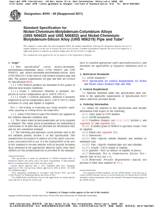
Designation:B444–06(Reapproved2011)Standard Specification forNickel-Chromium-Molybdenum-Columbium Alloys(UNS N06625and UNS N06852)and Nickel-Chromium-Molybdenum-Silicon Alloy(UNS N06219)Pipe and Tube1This standard is issued under thefixed designation B444;the number immediately following the designation indicates the year of original adoption or,in the case of revision,the year of last revision.A number in parentheses indicates the year of last reapproval.A superscript epsilon(´)indicates an editorial change since the last revision or reapproval.This standard has been approved for use by agencies of the Department of Defense.1.Scope*1.1This specification2covers nickel-chromium-molybdenum-columbium alloys(UNS N06625and UNS N06852)and nickel-chromium-molybdenum-silicon alloy (UNS N06219)*in the form of cold-worked seamless pipe and tube.The general requirements for pipe and tube are covered by Specification B829.1.1.1UNS N06625products are furnished in two grades of different heat-treated conditions:1.1.1.1Grade1(annealed)—Material is normally em-ployed in service temperatures up to1100°F(593°C).1.1.1.2Grade2(solution annealed)—Material is normally employed in service temperatures above1100°F(593°C)when resistance to creep and rupture is required.N OTE1—Hot-working or reannealing may change properties signifi-cantly,depending on working history and temperatures.1.1.2Alloys UNS N06219and UNS N06852are supplied in the solution annealed condition only.1.2The values stated in inch-pound units are to be regarded as standard.The values given in parentheses are mathematical conversions to SI units that are provided for information only and are not considered standard.1.3The following precautionary caveat pertains only to the test methods portion,Section9,of this specification:This standard does not purport to address all of the safety concerns, if any,associated with its use.It is the responsibility of the user of this standard to become familiar with all hazards including those identified in the appropriate Material Safety Data Sheet (MSDS)for this product/material as provided by the manufac-turer,to establish appropriate safety and health practices,and determine the applicability of regulatory limitations prior to use.2.Referenced Documents2.1ASTM Standards:3B829Specification for General Requirements for Nickel and Nickel Alloys Seamless Pipe and Tube3.General Requirement3.1Material furnished under this specification shall con-form to the applicable requirements of Specification B829 unless otherwise provided herein.4.Ordering Information4.1Orders for material to this specification shall include information with respect to the following:4.1.1Alloy name or UNS number,4.1.2ASTM designation,4.1.3Condition(temper)(see1.1.1,1.1.2,Section6,and Appendix X1and Appendix X2),4.1.3.1If neither grade of N06625is specified,Grade1will be supplied.4.1.4Finish(See Appendix X2),4.1.5Dimensions:4.1.5.1Tube—Specify outside diameter and nominal or minimum wall,4.1.5.2Pipe—Specify standard pipe size and schedule, 4.1.5.3Length—Cut to length or random,4.1.6Quantity—Feet(or metres)or number of pieces,4.1.7Hydrostatic Test or Nondestructive Electric Test—Specify type of test(see6.2),4.1.8Hydrostatic Pressure Requirements—Specify test pressure if other than required by9.1.1,1This specification is under the jurisdiction of ASTM Committee B02on Nonferrous Metals and Alloys and is the direct responsibility of Subcommittee B02.07on Refined Nickel and Cobalt and Their Alloys.Current edition approved May1,2011.Published May2011.Originally approved st previous edition approved in2006as B444–06.DOI: 10.1520/B0444-06R11.*New designation established in accordance with Practice E527and SAE J1086,Practice for Numbering Metals and Alloys(UNS).2For ASME Boiler and Pressure Vessel Code applications see related Specifi-cation SB-444in Section II of that Code.3For referenced ASTM standards,visit the ASTM website,,or contact ASTM Customer Service at service@.For Annual Book of ASTM Standards volume information,refer to the standard’s Document Summary page on the ASTM website.*A Summary of Changes section appears at the end of this standard. Copyright©ASTM International,100Barr Harbor Drive,PO Box C700,West Conshohocken,PA19428-2959,United States.4.1.9Certification—State if certification is required,4.1.10Samples for Product(Check)Analysis—State whether samples for product(check)analysis should be fur-nished(see5.2),4.1.11Purchaser Inspection—If purchaser wishes to wit-ness tests or inspection of material at place of manufacture,the purchase order must so state indicating which tests or inspec-tions are to be witnessed,and4.1.12Small-Diameter and Light-Wall Tube(Converter Sizes)—See Appendix X1and Table1.5.Chemical Composition5.1The material shall conform to the composition limits specified in Table2.One test is required for each lot as defined in Specification B829.5.2If a product(check)analysis is performed by the purchaser,the material shall conform to the product(check) analysis variations in Table2of Specification B829.6.Mechanical Properties and Other Requirements6.1Tension Test—The material shall conform to the tensile properties specified in Table1.The sampling and specimen preparation are as covered in Specification B829.6.2Hydrostatic or Nondestructive Electric Test—Each pipe or tube shall be subjected to either the hydrostatic test or to the nondestructive electric test.The type of test to be used shall be at the option of the manufacturer,unless otherwise specified in the purchase order.7.Dimensions and Permissible Variations7.1Permissible variations for material specified as small-diameter and light-wall tube(converter size)shall conform to the permissible variations prescribed in Table X1.1and Table X1.2.8.Number of Tests8.1Chemical Analysis—One test per lot.8.2Tension—One test per lot.8.3Hydrostatic or Nondestructive Electric Test—Each piece in each lot.9.Test Methods9.1Hydrostatic Test—Each pipe or tube with an outside diameter1⁄8in.(3mm)and larger and with wall thickness of 0.015in.(0.38mm)and over shall be tested in accordance with Specification B829.The allowablefiber stress for material in the condition furnished,is as follows:UNS N06625:Grade1—30000psi(207MPa)Grade2—25000psi(172MPa)UNS N06219:All—24000psi(165MPa)UNS N06852:All—21000psi(145MPa)9.1.1When so agreed upon by the manufacturer and pur-chaser,pipe or tube may be tested to11⁄2times the allowable fiber stress given above.9.1.2If any pipe or tube shows leak during hydrostatic testing,it shall be rejected.9.2Nondestructive Electric Test—Each pipe or tube shall be examined with a nondestructive electric test as per prescribed in Specification B829.10.Keywords10.1seamless pipe;seamless tube;N06219;N06625TABLE1Room Temperature Tensile Properties and Heat Treatment Including Small Diameter and Light-Wall Tubing(Converter Sizes)ABConditionTensileStrength,min,ksi(MPa)CYieldStrength(0.2%offset),min,ksi(MPa)CElongationin2in.or50.8mm(or4D),min,%Alloy N06625Grade1(annealed)D120(827)60(414)30 Grade2(solution annealed)E100(690)40(276)30 Alloy N06219All(solution annealed)96(660)39(270)30 Alloy N06852All(solution annealed)85(586)35(241)30A Not applicable to outside diameters under1⁄8in.(3.2mm)and to wall thicknesses under0.015in.(0.38mm).B Hot forming quality pipe and tubing is furnished to chemical requirements and surface inspection only.No tensile properties are required.C The minimum strength values apply only to tubing in straight lengths.D Annealed at1600°F(871°C)minimum.E Solution annealed at2000°F(1093°C)minimum,with or without subsequent stabilization anneal at1800°F(982°C)minimum to increase resistance to sensi-tization.TABLE2Chemical Requirements ElementComposition Limits,%N06852N06625N06219 Carbon0.05max0.10max0.05max Manganese0.50max0.50max0.50max Silicon0.50max0.50max0.70-1.10 Phosphorus0.015max0.015max0.020max Sulfur0.015max0.015max0.010max Chromium20.0-23.020.0min18.0-22.0...23.0max... Columbium+tantalum... 3.15min...... 4.15max... Columbium0.51-1.00...... Cobalt(if determined)... 1.0max 1.0max Molybdenum8.0-10.08.0min7.0-9.010.0max...Iron15.0-20.0 5.0max 2.0-4.0 Aluminum0.40max0.40max0.50max Titanium0.40max0.40max0.50max Copper......0.50max Nickel A Bal.58.0min Bal.A Element shall be determined arithmetically bydifference.APPENDIXES(Nonmandatory Information)X1.CONVERTER SIZESX1.1Small-diameter and light-wall tube in outside diam-eters 11⁄4in.(31.8mm)and under may be furnished in a limited range of sizes and the manufacturer should be consulted as to the various outside diameters and wall thicknesses that may be furnished.Material will have a bright finish.Such material shall conform to the requirements in Tables X1.1and X1.2.X2.CONDITIONS AND FINISHES NORMALLY SUPPLIEDX2.1ScopeX2.1.1This appendix lists the conditions and finishes in which pipe and tube (other than converter sizes)are normally supplied.These are subject to change,and the manufacturer should be consulted for the latest information available.X2.2Cold-Worked Tube and PipeX2.2.1Cold–Drawn,Annealed or Solution Annealed with Ground Outside Diameter —The inside diameter may have a bright finish when material is annealed or solution annealed in a protective atmosphere;otherwise,the inside diameter issupplied descaled as necessary.It is available in sizes 1⁄2to 4in.(12.7to 102mm),incl,in outside diameter in both normal and heavy-wall tube,and pipe sizes,all schedules,of correspond-ing outside-diameter dimensions.X2.2.2Cold–Drawn,Annealed or Solution Annealed and Pickled (Not Ground)—Outside and inside diameter will have dull,matte (pickled)surfaces.Available in sizes 1⁄2to 65⁄8in.(12.7to 168mm),incl,in outside diameter in both normal and heavy-wall tube,and pipe sizes,all schedules,of correspond-ing outside-diameter dimensions.TABLE X1.1Permissible Variations for Small-Diameter and Light-Wall Tube (Converter Sizes)A ,B ,C ,D ,E,F ,GSpecified Outside Diameter,in.(mm)Outside DiameterInside Diameter Wall Thickness,%PlusMinus,in.(mm)Plus Minus Plus Minus Under 3⁄32(2.4)3⁄32to 3⁄16(2.4to 4.8),excl 0.002(0.05)0.003(0.08)00000.002(0.05)0.003(0.08)101010103⁄16to 1⁄2(4.8to 12.7),excl 0.004(0.10)000.004(0.10)10101⁄2to 11⁄4(12.7to 31.8),incl0.005(0.13)00.005(0.13)1010A Ovality,Normal-Wall Tube —Ovality will be held within 2%of the theoretical average outside diameter.BOvality,Light-Wall Tube —Ovality will be held within 3%of the theoretical average outside diameter.CWall Tolerances,Light-Wall Tube —The plus and minus wall tolerance shown in the table shall apply down to and including 0.005in.(0.13mm)in wall thickness.For wall thicknesses less than 0.005in.(0.13mm),the tolerance shall be 60.0005in.(0.013mm).DRandom Lengths:Where nominal random lengths on tubing 1⁄8in.(3.2mm)and larger in outside diameter are specified,a length tolerance of 631⁄2ft (1.07m)applies to the nominal length.This is a total spread of 7ft (2.13m).Random lengths in sizes 1⁄8in.(3.2mm)and larger in outside diameter shall be subject to a length range of 5to 24ft (1.52to 7.32m).Long random lengths are subject to a range from 15to 22ft (4.57to 6.71m).Random lengths in sizes up to,but not including 1⁄8in.(3.2mm)in outside diameter,and fragile light-wall tubes over this outside diameter are subject to the length range from 1to 15ft (0.30to 4.57m).ECut Lengths —Tolerances on cut lengths shall be in accordance with Table X1.1.FStraightness —Round tubing is subject to a straightness tolerance of 1part in 600[equivalent to a depth of arc of 0.030in.(0.76mm)in any 3ft (0.91m)of length].GWhen specified,the tolerance spreads of this table may be applied as desired.However,when not specified,the tolerances in this table will apply.It should be noted that inside diameter tolerances are based upon the outside diameter range.TABLE X1.2Tolerances on Cut Lengths of Light-Wall TubeLength,ft (m)Tube Size,in.(mm)Permissible Variations,in.(mm)Over Under Under 1(0.30)1to 4(0.30to 1.22),inclup to 1.250(31.8),incl up to 1.250(31.8),incl 1⁄32(0.8)1⁄16(1.6)0(0)0(0)Over 4to 10(1.22to 3.0),incl up to 1.250(31.8),incl 3⁄32(2.4)0(0)Over 10(3.0)up to 1.250(31.8),incl3⁄16(4.8)0(0)SUMMARY OF CHANGESCommittee B02has identified the location of selected changes to this standard since the last issue(B444-04) that may impact the use of this standard.(Approved December1,2006.)(2)Revision of4.1,6.2,8.3,9.1.2,and9.2.(1)Introduction of nondestructive electric test in lieu ofhydrostatic test at the option of the manufacturer.ASTM International takes no position respecting the validity of any patent rights asserted in connection with any item mentioned in this ers of this standard are expressly advised that determination of the validity of any such patent rights,and the riskof infringement of such rights,are entirely their own responsibility.This standard is subject to revision at any time by the responsible technical committee and must be reviewed everyfive years and if not revised,either reapproved or withdrawn.Your comments are invited either for revision of this standard or for additional standardsand should be addressed to ASTM International Headquarters.Your comments will receive careful consideration at a meeting of theresponsible technical committee,which you may attend.If you feel that your comments have not received a fair hearing you shouldmake your views known to the ASTM Committee on Standards,at the address shown below.This standard is copyrighted by ASTM International,100Barr Harbor Drive,PO Box C700,West Conshohocken,PA19428-2959, United States.Individual reprints(single or multiple copies)of this standard may be obtained by contacting ASTM at the aboveaddress or at610-832-9585(phone),610-832-9555(fax),or service@(e-mail);or through the ASTM website().Permission rights to photocopy the standard may also be secured from the ASTM website(/COPYRIGHT/).。

Nickel200纯镍管棒材标准Nickel 200/201Nickel 200/201国内外对应牌号:圆钢、棒材、带材、管材、阀座、球体、法兰和锻件协商供应Nickel 200/201化学成分:Nickel 200/201物理性能:Nickel 200/201在常温下合金的机械性能的最小值:Nickel200/201是含碳量极低的纯商业性镍,已被批准用于服务高达1230℃的高温环境中。
Nickel 200/201应用范围应用领域有:1.食物加工处理设备,食盐提炼设备。
2.采矿和海洋开采。
3.在300℃以上的高温条件下制造工业氢氧化钠所需的设备。
4.有机或无机氯化物和氟化物的生产:抗氯气和氟气腐蚀5.核反应堆6.热处理炉中曲颈瓶及部件,尤其是在碳化和氮化气氛中7.石油化工生产中的催化再生器在700℃以上的应用中推荐使用合金600以获得较长的使用寿命。
/201Nickel 200/201国内外对应牌号:Nickel 200/201供货规格:圆钢、棒材、带材、管材、阀座、球体、法兰和锻件协商供应Nickel 200/201化学成分:Nickel 200/201在常温下合金的机械性能的最小值:Nickel 200/201具有以下特性:Nickel200/201是含碳量极低的纯商业性镍,已被批准用于服务高达1230℃的高温环境中。
Nickel 200/201应用范围应用领域有:1.食物加工处理设备,食盐提炼设备。
2.采矿和海洋开采。
3.在300℃以上的高温条件下制造工业氢氧化钠所需的设备。
4.有机或无机氯化物和氟化物的生产:抗氯气和氟气腐蚀5.核反应堆6.热处理炉中曲颈瓶及部件,尤其是在碳化和氮化气氛中7.石油化工生产中的催化再生器在700℃以上的应用中推荐使用合金600以获得较长的使用寿命。

张工:158 – 0185 - 9914Nickel 200合金具有以下特性:Nickel200 是纯商业性(99.6%)造成的镍,具有优良的力学性能和耐腐蚀性,较高的热导率和电导率,低气体含量和低蒸汽压力。
Nickel 200应用领域:食物加工处理设备,食盐提炼设备。
采矿和海洋开采。
在300℃以上的高温条件下制造工业氢氧化钠所需的设备。
p>采矿和海洋开采。
在300℃以上的高温条件下制造工业氢氧化钠所需的设备。
产品:哈氏合金、高温合金、铜镍合金、英科耐尔、蒙乃尔、钛合金、沉淀硬化钢等各种中高端不锈钢,镍基合金等。
高温合金:GH3030、GH4169、GH3128、GH145、GH3039、GH3044、GH4099、GH605、GH5188等软磁合金:1J06、1J12、1J22、1J27、1J30、1J36、1J50、1J79、1J85等弹性合金:3J01、3J09、3J21、3J35等。
蒙乃尔合金:Monel 400(N04400)、Monel K500(N05500)等膨胀合金:4J28、4J29(与玻璃烧结)、4J32、4J33、4J34、4J36、(与陶瓷烧结)4J38、4J42、4J50等耐蚀合金:Inconel 600、601、617、625、686、690、713C、718、Inconel X-750等因科洛伊合金:Incoloy 20、330、718、800、800H、800HT、825、925、Inconel 926【N08926/1.4529】等哈氏合金:Hastelloy C、C-4、C-22(N06022)、C-276、C-2000、Hastelloy B、B-2、B-3等纯镍 / 钛合金:N4、N5(N02201)N6、N7(N02200)TA1、TA2、TA9、TA10、TC4等沉淀硬化钢/双相不锈钢17-4PH(sus630)、17-7PH(sus631)、15-5PH/ 2205、2507、904L、254SMO、20#(N08020)生产工艺:热轧、锻轧、精扎、机轧、挤压、连铸、冷拔、浇铸、冷拉等供应规格:棒材、板材、管材、带材、毛细管、丝材及块料。
镍白铜管标准镍白铜管是一种由铜、镍和锌组成的合金管材,具有良好的耐蚀性、抗磨损性和导热性能。
镍白铜管广泛应用于化工、海洋工程、船舶制造、电力工业等领域。
为了确保镍白铜管的质量和使用效果,制定了一系列的标准。
1. 镍白铜管材质标准:镍白铜管的材质标准主要有GB/T2059-2000和ASTM B111两个。
GB/T2059-2000是中国国家标准,规定了镍白铜管的化学成分、机械性能、尺寸和表面质量等要求。
ASTM B111是美国材料和试验协会制定的标准,也规定了镍白铜管的化学成分、机械性能和尺寸等要求,但与GB/T2059-2000在一些细节方面存在差异。
2. 镍白铜管尺寸标准:镍白铜管的尺寸标准主要有GB/T8890-2006和ASTM B466两个。
GB/T8890-2006是中国国家标准,规定了镍白铜管的外径、壁厚和长度等尺寸要求。
ASTM B466是美国材料和试验协会制定的标准,也规定了镍白铜管的外径、壁厚和长度等尺寸要求,但与GB/T8890-2006在一些细节方面存在差异。
3. 镍白铜管化学成分标准:镍白铜管的化学成分标准主要有GB/T4423-2007和ASTM B171两个。
GB/T4423-2007是中国国家标准,规定了镍白铜管的化学成分要求,包括铜、镍和锌的含量范围。
ASTMB171是美国材料和试验协会制定的标准,也规定了镍白铜管的化学成分要求,但与GB/T4423-2007在一些细节方面存在差异。
4. 镍白铜管机械性能标准:镍白铜管的机械性能标准主要有GB/T15052-1994和ASTM B466两个。
GB/T15052-1994是中国国家标准,规定了镍白铜管的抗拉强度、屈服强度、伸长率和硬度等机械性能要求。
ASTM B466是美国材料和试验协会制定的标准,也规定了镍白铜管的抗拉强度、屈服强度、伸长率和硬度等机械性能要求,但与GB/T15052-1994在一些细节方面存在差异。
镍铜合金NCu40-2-1
镍铜合金NCu40-2-1
概述:
Ni和Cu可以任何比例混合而成固溶体合金,称为Monel合金。
Ni 和Cu具有较好的耐HF、海水盐水及缝隙腐蚀性能。
Monel合金Ni70Cu30是最早的镍基耐蚀合金。
它既具有较高的强度和韧性,又具有优良的抗还原酸及强碱介质和海水等腐蚀的性能,通常用于制造输送氢氟酸(HF)、盐水、中性介质、碱盐及还原性酸介质的设备。
执行标准:GB/T5235-2007
化学成分:
小大
Ni+Co 余量
Cu 38.0 42.0
Si 0.15
Mn 1.25 2.25
C 0.30
Mg
S 0.02
P 0.005
Fe 0.2 1.0
Pb 0.006
As
Sb
Ti
Al
产品形状:板带管棒线
特性:
镍铜合金有较好的室温力学性能和高温强度,耐蚀性高耐磨性好,容易加工,无磁性,是制造行波管和其他电子管较好的结构材料。
还
可作为航空发动机的结构材料。
规格范围:
板材:厚壁规格(min-max):Φ0.1mm-Φ200.0mm 丝材:Φ0.1mm-Φ3.0mm
直条或卷条:Φ2.0mm–Φ300.0mm
我公司材料之多不能一一列出,以上部分供参考。
上海商虎:TEL:①⑤③①⑥②O⑤⑧⑧⑥。
B211B•ApplicationChrome Plated Brass Ball and Nickel Plated Brass StemTechnical dataFunctional dataValve Size 0.5" [15]Fluidchilled or hot water, up to 60% glycol Fluid Temp Range (water)0...250°F [-18...120°C]Body Pressure Rating 600 psi Close-off pressure ∆ps 200 psiFlow characteristic equal percentage Servicing maintenance-free Flow Pattern 2-way Leakage rate0% for A – AB Controllable flow range 75°Cv1.9 Body pressure rating note 600 psiCv Flow RatingA-port: as stated in chart B-port: 70% of A – AB Cv MaterialsValve body Nickel-plated brass body Stem seal EPDM (lubricated)SeatPTFEPipe connection NPT female ends O-ring EPDM (lubricated)Ballchrome plated brass Suitable actuatorsNon-SpringTR LRB(X)Safety notesWARNING: This product can expose you to lead which is known to the State of California to cause cancer and reproductive harm. For more information go to Product featuresThis valve is typically used in air handling units on heating or cooling coils, and fan coil unit heating or cooling coils. Some other common applications include Unit Ventilators, VAV box re-heat coils and bypass loops. This valve is suitable for use in a hydronic system with variable flow.Flow/Mounting detailsB211B DimensionsDimensional drawingsLRB, LRXA B C D E F H1H29.4" [239] 2.4" [60] 5.2" [132] 4.6" [117] 1.3" [33] 1.3" [33] 1.2" [30] 1.1" [28]TRA B C D E F3.7" [95] 2.4" [60]4.8" [122] 4.2" [107] 1.3" [33] 1.3" [33]TFRB, TFRXA B C D E F6.6" [167] 2.4" [60] 4.9" [124] 4.3" [110] 1.5" [39] 1.5" [39]LFA B C D E F7.9" [200] 2.4" [60] 5.7" [146] 5.1" [129] 1.8" [46] 1.8" [46]A B C D E F7.9" [200] 2.4" [60] 5.7" [146] 5.1" [129] 1.8" [46] 1.8" [46]TFRB, TFRXA B C D E F6.6" [167] 2.4" [60] 4.9" [124] 4.3" [110] 1.5" [39] 1.5" [39]LRB120-3•••••On/Off, Floating Point, Non-Spring Return, AC 100...240 VTechnical dataElectrical dataNominal voltageAC 100...240 V Nominal voltage frequency 50/60 Hz Power consumption in operation 2 W Power consumption in rest position 0.5 WTransformer sizing 4 VA (class 2 power source)Electrical Connection 18 GA appliance cable, 3 ft [1 m], with 1/2" conduit connectorOverload Protectionelectronic throughout 0...95° rotation Functional dataInput Impedance 600 ΩDirection of motion motor selectable with switch 0/1Manual override external push button Angle of rotation 90°Angle of rotation note adjustable with mechanical stop Running Time (Motor)90 s Noise level, motor 35 dB(A)Position indicationMechanically, pluggable Safety dataDegree of protection IEC/EN IP54Degree of protection NEMA/UL NEMA 2 UL Enclosure Type 2Agency ListingcULus acc. to UL60730-1A/-2-14, CAN/CSAE60730-1:02, CE acc. to 2014/30/EU and 2014/35/EU; Listed to UL 2043 - suitable for use in air plenums per Section 300.22(c) of the NEC and Section 602.2 of the IMC Quality Standard ISO 9001Ambient temperature -22...122°F [-30...50°C]Storage temperature -40...176°F [-40...80°C]Ambient humidity max. 95% r.H., non-condensing Servicingmaintenance-free WeightWeight1.1 lb [0.50 kg]Safety notes3/8”-16 shaft clevis for AHK/AH.Battery Back Up System for SY(7~10)-1105/16” shaft clevis for LH.Cable to ZIP-RS232 US to diagnostic/programming socket.MFT95 resistor kit for 4 to 20 mA control applications.Electrical installationLRB120-3INSTALLATION NOTESActuators with appliance cables are numbered.Provide overload protection and disconnect as required.Actuators may be connected in parallel. Power consumption and input impedance must be observed.Meets cULus requirements without the need of an electrical ground connection.Warning! Live Electrical Components!During installation, testing, servicing and troubleshooting of this product, it may be necessary to workwith live electrical components. Have a qualified licensed electrician or other individual who has beenproperly trained in handling live electrical components perform these tasks. Failure to follow all electricalsafety precautions when exposed to live electrical components could result in death or serious injury.On/Off AC 100...240 V Floating Point AC 100...240 V。
ASME A112.18.1-2005/CSA B125.1-05管道安装部件1 范围1.1本标准适用于位于管路终点和终端装置之间的管道安装部件及其配件,包括如下:(a) 用于独立入墙式淋浴系统的自动补偿阀(b) 浴室和花洒供水装置(c) 坐浴盆供水装置(d) 洗衣盆供水装置(e) 饮水机供水装置(f) 增湿器供水止水阀(g) 厨房, 洗涤盆和面盆供水装置(h) 洗衣盆供水装置(i) 草坪和沉淀池龙头(j) 计量且自动关闭的供水装置和(k) 供水止水阀1.2管道附件由标准ASME A112.18.2/CSA B125.2 定义1.3其他装置,如: 在连续压力下的温控混合阀和柔性连接体,由CSA B125.3 或其他管路产品标准定义1.4本标准不适用于常规管道或管道装置1.5在本标准内, “shall”表示要求,即使用者为应用此标准必须满足的条件; “should” 表示推荐或某些建议但非强制要求; “may”表示一种选择或某些在本标准内允许的情况. 文本后附的备注不包括要求或选择性的要求; 文本后备注的目的是将文本说明和材料来源分开. 表格和图片的备注被认为是表格或图片的一部分,作为要求处理.1.6不论是以SI(公制)还是以码/磅(英制)表示的数值均被认为是标准的. SI(公制)单位用于加拿大(Canada)的报告.在本标准内,括号内的为码/磅等英制单位. 这些数值在每个测量系统同等应用; 但是每个系统必须独立使用. 来自两个测量系统的混合数值不适应于本标准.所有提到的加仑都是美制加仑.关于本标准的转换标准的相关信息见附录A.2参考资料ASME 和CSA出版物本标准参考了如下资料,而且在每个有参考的条款后面都备注参考方目的版本及相关改版记录ASME 国际(美国机械工程协会)A112.1.2-1991(R2002)Air Gaps in Plumbing Systems管道系统的空气间隙A112.18.2-2005/CSA B125.2-2005Plumbing Waste Fittings 管道附件装置A112.18.3-2002Performance Requirements for Backflow Devices and Systems in Plumbing Fixture Fittings反逆流装置和管道装置系统的性能要求B1.20.1-1983(R2001)Pipe Threads, General Purpose, Inch 管道螺纹,一般应用(英寸)B1.20.7-1991(R2003)Hose Coupling Screw Threads, Inch软管连接螺丝螺纹(英寸)B16.18-2001Cast Copper Alloy Solder Joint Pressure Fittings铸造铜合金焊接压力装置B16.22-2001锻造铜和铜合金焊接压力装置B16.26-1988Cast Copper Alloy Fittings for Flared Copper Tubes 用于广口铜管的铸造铜合金装置PTC 19.2-1987 (R1998)Pressure Measurements, Instruments and Apparatus 压力测量,工具和装置PTC 19.5-1972Application Part II of Fluid Meters: Interim Supplement to Ptc 19.5 on Instruments and Apparatus 流体仪表的应用II: 关于工具和装置PTC 19.5 的中间装置CSA (Canadian Standards Association)ASME A112.18.2-2005/CSA B125.2-05Plumbing waste fittings 管道装置附件CAN/CSA-B64 Series-01Backflow preventers and vacuum breaks 防回流器及真空破坏器B125.3-05Plumbing fittings 管道装置CAN/CSA-C22.2 No.223-M91(R1999)Power supplies with extra-low-voltage Class 2 outputs其它参考资料本标准参考了如下资料,而且在每个有参考的条款后面都备注参考方目的版本及相关改版记录ASSE(American Society of Sanitary Engineering) 美国卫生工程协会1016-2005用于独立花洒和花洒水嘴组合的自动补偿阀1019-1997Performance Requirements for Vacuum Breaker Wall Hydrants, Freeze Resistant, Automatic Drawing Type入墙式出水器,防冻装置,自动排水装置的真空断路器性能要求ASTM International( American Society for Testing and Materials) 美国测试和原料协会B 117-03Standard Practice for Operating Salt Spray (Fog) Apparatus 盐雾实验装置标准操作B 368-97(2003) e1Standard Method for Copper-Accelerated Acetic Acid-Salt Spray(Fog) Testing (CASS Test)铜加速盐雾试验方法B 380-97(2002)Standard Test Method of Corrosion Testing of Decorative Electrodeposited Coatings by the Corrodkote Procedure 通过Corrodkote程序测试电镀层腐蚀性的测试方法.B 571-97(2003)Standard Practice for Qualitative Adhesion Testing of Metallic Coatings.金属涂层的粘着性试验D 968-93(2001)Standard Test Methods for Abrasion Resistance of Organic Coatings by Falling Abrasive有机镀层耐磨擦性标准测试方法—落砂测试D 3359-02Standard Test Method for Measuring Adhesion by Tape Test带式测量附着性标准测试方法D 4060-01Standard Test Method for Abrasion Resistance of Organic Coatings by the Taber Abraser有机镀层的耐磨性标准测试方法——砂轮机测试G 85-02e1Standard Practice for Modified Salt Spray (Fog) TestingISA (Instrumentation, Systems, and Automation Society) 工具、系统和自动化协会ANSI/ISA-75.02-1996Control Valve Capacity Test Procedure 控制阀容量测试程序MC96.1-1982Temperature Measurement Thermocouples 测温热电偶ISO(International Organization for Standardization) 国际标准协会228-1: 2000Pipe threads where pressure-tight joints are not made on the threads – Part I: Dimensions, tolerances and designation非压力紧固接头的管道螺纹-----部分1:尺寸,公差和设计NSF InternationalNSF/ANSI 61-2003eDrinking Water System Components – Health Effects饮用水系统组件-----健康影响SAE International (Society of Automotive Engineers) 汽车工程协会J512 (April 1997)Automotive Tube Fittings 汽车管道装置UL(Underwriters Laboratories Inc.)保险商实验所1310 (1994)Standard for Class 2 Power Units 2级能量单位标准1585(1998)Standard for Class 2 and Class 3 Transformers 2和3转换标准3 定义和简写3.1 定义本标准应用的定义如下:易接近的:容易维修或容易更换的。
K M E G e r m a n y G m b H & C o . K G O S N A ® 10 [G B ]Copper-Nickel Seawater Piping Systems Offshore product range:Pipes, fittings and flanges of OSNA ®10123456891012131417192022232444ContentsYour Partner KME The MaterialOffshore Product Range Design ScopeKME Quality-Management Pipes Elbows Equal Tees Reducing Tees Caps Reducers Saddle PiecesComposite Weld Neck Flanges Composite Slip-On Flanges Solid Weld Neck Flanges Solid Slip-On Flanges Composite Blind FlangesCapillary Brazing, Socket Weld Fittings and Miscellaneous AppendixYour Partner - KMEThe Expert in Seawater PipingMarine ApplicationsKME’s division Marine Applications specializes in the production and supply of copper-nickel alloys for seawater piping system. Since decades, these alloys have successfully used in: • Merchant and military shipbuilding • Offshore oil and gas installations• Coastal petroleum and petrochemical processing plants• Seawater desalination plants• Coastal electricity generation plantsHundred years of experience, a thorough understanding of the different industries’ specific problems, a potent range of application-oriented products and services, plus qualified technical advice and assistance, have been the bedrock ofKME’s relations with its customers.Copper-nickel alloys are widely applied in: • Seawater cooling systems • Fire water systems • Sanitary systems • Deck steam pipes • Deluge systems• Hydraulic and pneumatic systems• Seawater feed lines to desalination and processing units• Splash zone sheathing1) no longer valid 2)equal to C 70600 for subsequent welding* The iron content has been specified to improve corrosion resistanceMain Advantages of OSNA ®10-AlloyDespite the rough conditions in marine service and the highly corrosive nature of seawater, the products provide well balanced combination of technical and economical advantages:• Simple alloying system with good weldability • Excellent ductility and toughness• Outstanding erosion corrosion performance • Resistant to uniform and localised corrosion • No effect of ambient seawater temperatures • No effect of seawater chlorination • Resistant to biofouling• Resistant to stress-corrosion cracking • Low maintenance costs • A lot of design experienceKME OSNA ®10-AlloyThe chemical composition of the KME’s OSNA ®10-alloy is modified to ensure the compliance with all international specifications. Controlled content of alloying elements and minimised concentration of impurities ensure reliable service and fabrication properties of the alloy.The MaterialOffshore Product Range The OSNA®10 offshore product range is based on:• EEMUA –144: 1987 Tubes1 Seamless and Welded • EEMUA –145: 1987 Flanges Composite and Solid • EEMUA –146: 1987 FittingsThe unique dimensional range from ½ inch to36 inch ensures the supply of the entire piping systems from one source. Although the pipe dimensions of 38 and 40 inch are not includedin the EEMUA 144 – 1987 they are availablehere as they are commonly specified in offshore projects. Based on ASME specifications, additional components are included.1 The reference …pipe“ rather than …tube“ is used in this document.Design ScopeWorking pressures and temperatures of components included in this specification:1. 16 bar/232 psi: -29°C/-20°F to +75°C/+167°F2. 20 bar/290 psi: -29°C/-20°F to +38°C/+100°FPipes Seamless and Welded:• Pipes are based on BS MA 60, DIN 86007, and ANSI/ASME B31.3• The wall thicknesses comply with ANSI B31.3 and DIN 86007 as well as International Association of Classification Societies with additional allowances for robustness to withstand mechanical damage, especially in the smaller sizes.• The fit-for-purpose corrosion allowance of 0.5 mm sufficient for entire service life of the piping installation has been included. This corrosion allowance is in accordance with all major classi-fication societies specified for alloys containing ≥10 wt. % Ni and ≥1.5 wt. % Fe. Mechanical properties of pipes are given in Appendix A.Flanges Composite and Solid:• Included series of composite (lap type) and solid flanges in metric dimensions based on ANSI B16.5, MSS SP-44 and BS 1560• The basic metric dimensions for drilling and flange outside diameters are those given in ANSI B16.5 and MSS SP 44 Class 150 rating with inch size bolting.• The copper-nickel stub end and flange joint faces are machine finished and comply with the corresponding Sections of EEMUA 145 and are summarized in the Appendix A.• Mechanical properties pressure/temperature ratings of flanges are given in Appendix A.Fittings:• The specification comprises a series for pipe fittings including butt weld, socket welding, capillary brazing, threaded, self-reinforced fittings as well as saddle pieces.• The “building in” dimensions of the butt welding fittings are based on ANSI B16.9 apart from the caps that are based on DIN 28011 (with suitable amendments).• Mechanical properties pressure/temperature ratings of fittings are given in Appendix A. Physical Properties of CuNi 90/10The physical properties of the alloy are givenby Appendix B. The basic allowable stresses in tension are in accordance with ASME B31.3 Table A-1.WeldingThe welding consumables used for the manufac-turing of welded components are in accordance with AWS-A5.7 Class ER CuNi. The welding pro-cedure specification and welder qualification are in accordance with ASME code, section IX. Testing of WeldsThe weld seams are examined by the liquid dye penetrant testing in accordance with ASME code, section VIII, division 1, appendix 8. The radiogra-phic examination is performed for the complete length of each weld to meet the requirements of ASME code, section VIII, UW51.GasketsThe gaskets normally used with flanges are those made from aramid fibre with nitrile binder in accordance with ASME B16.21 or equivalent. The gasket hardness shall not be less than75 Shore. The gaskets shall not be graphited.In order to ensure adequate seating when solid weldneck and solid slip-on flanges are used, irrespective of gasket materials, the gaskets shall be located within the bolt circle. Note: Gaskets should not be used when mating with elastomerlrubber faced flanges.Suggested Branch ConnectionsSuggested branch connections are provided by Appendix D.PDMS DataThe components mentioned in this catalogue are available in the PDMS-format. Please contact usfor more information.KME Quality-ManagementQuality is the very basis of reliability – quality in every detail,in every step of work.For decades now, KME has been consistently putting into actionthe corporate idea of quality, and, with it, gained the reputationof being a reliable supplier throughout the world. The fulfilment of our customers expectations as to KME products and services inall re s pects is the declared corporate policy. To assure this, KME Quality Management System has been set up, implemented and certified to DIN EN ISO 9001 by Lloyd’s Register Quality Assuranceat all KME locations.KME Quality Management System comprehends process-integrated quality controls, internal product and system audits, the systematical training of all employees and the operating of computer aided statistical methods.The results of KME production give convincing proof: our results have been surpassing the requirements of national and international standards for years.KME produces quality.PipesSeamless PipesSeamless pipes are in accordance with EEMUA–144, Section 1. They are manufactured from hot extruded shells followed by cold work and annealing.Welded PipesLongitudinally welded pipes are in accordance with EEMUA–144, Section 2. They are manufac-tured from hot rolled or cold rolled and annealed sheet or plates in accordance with BS 2870, BS 2875, ASTM B171 or ASTM B402. Mechanical testing is carried out in accordance with the standards above. The pipes are supplied in “as welded” condition.DimensionsDimensions are based on EEMUA –144,Tables 1.2.1-1.2.2 and 2.2.1-2.2.2. However,the pipe diameters range from ½ in./16 mm to 36 in./914 mm. Although the pipe dimensionsof 38 in./965 mm and 40 in./1016 mm are not included in the EEMUA 144 – 1987 they are available on request as they are commonly spe-cified. The corresponding wall thicknesses of the pipes comply with the pressure containment requirements of ASME B31.3 as well as the requirements of the International Association of Classification Societies. Pipes with other wallthicknesses are available on request.TolerancesSee notes 1-4 for seamless and notes 2-4 forwelded pipes.Weld PreparationFor wall thickness less than 3 mm, the pipes aresupplied with plain weld ends. Larger thicknessesare supplied with the weld bevel of 37 ½°±2 ½°.Dimensions (mm) Seamless PipeSize SizeNominal (in)Specified (mm)½16¾251301¼381½44.52572½76.1388.9410861598219.110267 12323.91436816419Seam-Welded PipeSize Size Nominal (in)Specified (mm) 1641918457.22050824610287113281336914Note 1The pipe sizes up to including 4 in./108 mm are based on BS 2871: Part 2: Table 3 for outside dia-meters and their tolerances to allow for the use of capillary and compression fittings and brazed (and welded) slip-on flanges. The wall thickness of the 16 bar range have been increased to match the 20 bar range for mechanical strength.Note 2The pipe size 6 in./159 mm up to 16 in./419 mm are also based on BS 2871: Part 2: Table 3 for specified diameters but the tolerance have been applied to the inside diameters for facilitate alignment of matching weld preparations. The ovality of the finished pipe doesn’t exceed 2% of the difference of the maximum and minimum diameter measured on the same cross section. Note 4Up to including 4 in./108 mm, the wall thickness doesn’t vary by more than 10 % specified therein. For diameters from 6in./159 mm and larger, the wall thickness is not less than 12.5 % of the spe-cified value.The pipes with other dimensions than mentioned herein are available on request. Please contact us for more information.Stock DimensionsAll seamless pipes are available from stock.Elbowst i = intrados thickness (min) in accordance with EEMUA Publication No. 146: Section 1, Table 1.5Dimensions (mm)Nominal SpecifiedSize Size (OD)in mm 1301¼381½44.52572½76.1388.9410861598219.11026712323.9143681641918457.22050824610287113281336914Type and ConstructionElbows are in accordance with EEMUA–146, Section 1. Seamless elbows are typically availa-ble up to 18 inch/457 mm. Larger dimensions are manufactured from longitudinally welded half shells. 45° and 90° elbows are available in all sizes.DimensionsDimensions are based on EEMUA–146, Section 1, Figure 1.1, Tables 1.1-1.2 and 1.4-1.5., Standard elbows are supplied with long radius, i.e. 1.5 x O.D. Elbows with other dimensions are available on request. Tolerances See Appendix CWeld PreparationFor wall thickness less than 3 mm, the elbows are supplied with plain weld ends. Larger thicknesses are supplied with the weld bevel of 37 ½°±2 ½°.Dimensions (mm)Nominal Specified Size Size (OD)in mm 1301¼381½44.52572½76.1388.9410861598219.11026712323.9143681641918457.22050824610287113281336914Type and ConstructionTee pieces are in accordance with EEMUA–146, Section 1. Seamless tee pieces are typically available up to 8 in./219 mm; bigger dimensions are welded.DimensionsDimensions are based on EEMUA -146, Section 1, Figures 1.1-1.2, Tables 1.1-1.2 and 1.6. Tee pieces with other dimensions are available on request. Tolerances See Appendix CWeld PreparationFor wall thickness less than 3 mm, the tees are supplied with plain weld ends. Larger thicknesses are supplied with the weld bevel of 37 ½°±2 ½°.Equal TeesDimensions for 16 bar systemsSpecified SizePipe Wall Thickness Centre-to-End (mm)Approx.E E 1WeightOD mmOD mmOD 1 mm t mmt mmt 1 mm nomnom kgfor sizes from 30 mm up to 108 mm use 20 bar1083.01304.1915915988.9 3.03.02.5143124 4.01 76.1 2.5121 3.961593.01689.33 219.1219.1108 4.04.03.01781568.97 88.9 2.51528.82 219.14.020315.94267267159 4.54.53.021619415.06108 3.018414.712674.524127.48 323.9323.9219.1 5.55.54.025422926.49159 3.021925.62 323.95.527040.87368368267 6.56.54.527925739.07 219.1 4.024838.203686.530555.46419419323.97.07.05.530529553.38267 4.528351.624197.033077.10 457.2457.23688.08.06.534333075.59 323.9 5.532173.45 457.28.0368101.915085084198.58.57.038135698.68368 6.535697.165088.5432167.14610610457.210.510.58.0432419163.524197.0406160.2161010.5508271.2271171150812.012.08.5521483259.52 457.28.0470255.8871112.0572399.1481381361013.513.510.5597559387.175088.5533375.3481313.5648581.7791491471115.515.512.0673622562.8261010.5610551.05Type and ConstructionPieces are in accordance with EEMUA –146, Section 1. Seamless tee pieces are typically available up to 8 in./219 mm; bigger dimensions are welded. DimensionsDimensions are based on EEMUA -146, Section 1, Figures 1.1-1.2, Tables 1.1-1.2 and 1.7.1-1.7.3. Tee pieces with other dimensions are available on request. Tolerances See Appendix CWeld PreparationFor wall thickness less than 3 mm, the tees are supplied with plain weld ends. Larger thicknesses are supplied with the weld bevel of 37 ½°±2 ½°.Dimensions for 20 bar systemsSpecified Size Pipe Wall Thickness Centre-to-End (mm)Approx.E E1WeightOD mm OD mm OD1 mm t mm t mm t1 mm nom nom kg 303025 2.5 2.5 2.038380.18 383830 2.5 2.5 2.548480.2925 2.5 2.5 2.00.2838 2.5 2.5 2.50.4244.5 44.530 2.5 2.5 2.557570.4025 2.5 2.5 2.00.3844.5600.58575738 2.5 2.5 2.564570.5630510.5357700.9076.1 76.1 44.5 2.5 2.5 2.576670.8738640.8576.183 1.2488.9 88.957 2.5 2.5 2.58676 1.1644.573 1.1288.998 2.12108108 76.1 3.0 3.0 2.510595 2.065789 1.98108 3.0130 4.80 15915988.9 3.5 3.5 2.5143124 4.6276.1 2.5121 4.57159 3.516810.50 219.1219.1108 4.5 4.5 3.017815610.0288.9 2.51529.87219.1 4.520319.25 267267159 5.5 5.5 3.521619418.29 108 3.018417.82267 5.524134.69 323.9323.9219.17.07.0 4.525422933.32 159 3.521932.38323.97.027050.27 3683682678.08.0 5.527925747.87219.1 4.524846.663688.030570.63 419419323.99.09.07.030529568.24 267 5.528365.894199.033092.04 457.2457.23689.59.58.034333089.74 323.97.032187.31457.29.5368130.03 50850841911.011.09.0381356127.00 3688.0356124.6950811.0432206.90 610610457.213.013.09.5432419201.044199.0406197.9161013.0508337.26 71171150815.015.011.0521483323.65 457.29.5470317.7871115.0572500.07 81381361017.017.013.0597559484.85 50811.0533471.0981317.0648712.24 91491471119.019.015.0673622688.1461013.0610673.17Type and ConstructionEnd caps are in accordance with EEMUA –146, Section 1 and seamless.DimensionsDimensions are based on EEMUA -146, Section 1, Figure 1.1, Tables 1.1-1.2 and 1.8. The additional wall compensatory thicknesses over and above the minimum pipe wall thicknesses are included. Caps with other dimensions are available on request.TolerancesSee Appendix CWeld PreparationFor wall thickness less than 3 mm, the caps are supplied with plain weld ends. Larger thicknesses are supplied with the weld bevel of 37 ½°±2 ½°.Caps20 barSpecified t min HSize OD mm mm44.5 2.2519.657 2.2522.076.1 2.2525.788.9 2.2528.2108 2.7031.7159 3.1244219.1 3.5455 4.2960267 4.2969 5.2369323.9 5.2480 6.3485368 5.90937.21103419 6.731028.21112457.27.331198.971195088.151299.961396109.8114811.9616371111.5017613.9719181313.1720015.9721091414.8122117.962312.0 2.403.44.105.97.709.111.9012.416.9017.620.9022.730.8039.251.6061.881.4090.5117.40132.2166.20Type and ConstructionEccentric and concentric reducers are in accordance with EEMUA –146, Section 1. The concentric reducers are typically supplied up to incl. 12 in./323.9 mm in seamless condition; bigger dimen-sions are seamwelded. The eccentric reducers are supplied up to incl. 8 in./219.1 mm in seamless condition; bigger dimensions are seamwelded.ReducersSpecified Size LengthSpecified Wall Thickness t x t 1Approx. Weight OD H 16 bar 20 bar 16 bar20 barmm mm mm mm kg kg 57 x 3076 2.5 x 2.5 2.5 x 2.50.290.29 57 x 3876 2.5 x 2.5 2.5 x 2.50.290.29 57x 44.576 2.5 x 2.5 2.5 x 2.50.290.29 76.1 x 5789 2.5 x 2.5 2.5 x 2.50.400.40 88.9 x 5789 2.5 x 2.5 2.5 x 2.50.440.44 88.9 x 76.189 2.5 x 2.5 2.5 x 2.50.500.50 108 x 57102 3.0 x 2.5 3.0 x 2.50.670.67 108 x 76.1102 3.0 x 2.5 3.0 x 2.50.750.75 108 x 88.9102 3.0 x 2.5 3.0 x 2.50.800.80 159x 57140 3.0 x 2.5 3.5 x 2.5 1.32 1.54 159 x 76.1140 3.0 x 2.5 3.5 x 2.5 1.44 1.68 159 x 88.9140 3.0 x 2.5 3.5 x 2.5 1.52 1.77 159 x 108140 3.0 x 3.0 3.5 x 3.0 1.64 1.91 219.1 x 76.1152 4.0 x 2.5 4.5 x 2.5 2.49 2.79 219.1 x 88.9152 4.0 x 2.5 4.5 x 2.5 2.60 2.92 219.1 x 108152 4.0 x 3.0 4.5 x 3.0 2.77 3.11 219.1 x 159152 4.0 x 3.0 4.5 x 3.5 3.21 3.60 267 x 108178 4.5 x 3.0 5.5 x 3.0 4.84 5.89 267 x 159178 4.5 x 3.0 5.5 x 3.5 5.52 6.71 267 x 219.1178 4.5 x 4.0 5.5 x 4.5 6.317.68 323.9 x 159203 5.5 x 3.0 7.0 x 3.57.639.65 323.9 x 219.1203 5.5 x 4.0 7.0 x 4.58.6010.89 323.9 x 267203 5.5 x 4.5 7.0 x 5.59.3811.87 368 x 219.1330 6.5 x 4.0 8.0 x 4.517.2421.50 368 x 267330 6.5 x 4.5 8.0 x 5.518.6823.00 368 x 323.9330 6.5 x 5.5 8.0 x 7.020.3925.00 419 x 267356 7.0 x 4.5 9.0 x 5.523.4430.00 419 x 323.9356 7.0 x 5.5 9.0 x 7.025.4332.50 419x 368356 7.0 x 6.5 9.0 x 8.026.9734.50 457.2 x 323.9381 8.0 x 5.5 9.5 x 7.030.7037.03 457.2 x 368381 8.0 x 6.5 9.5 x 8.034.0641.50 457.2 x 419381 8.0 x 7.0 9.5 x 9.037.9046.50 508 x 368508 8.5 x 6.5 11.0 x 8.050.8064.10 508 x 419508 8.5 x 7.0 11.0 x 9.055.4071.10 508 x 457.2508 8.5 x 8.0 11.0 x 9.561.2075.70 610 x 419508 10.5 x 7.0 13.0 x 9.070.0087.50 610 x 457.2508 10.5 x 8.0 13.0 x 9.576.3092.50 610 x 508508 10.5 x 8.513.0 x 11.081.80102.80 711 x 457.2610 12.0 x 8.015 x 9.5109.30133.60 711 x 508610 12.0 x 8.515 x 11.0116.30146.70 711x 610610 12.0 x 10.515 x 13.0137.30170.10 813 x 508610 13.5 x 8.517 x 11136.40172.60 813 x 610610 13.5 x 10.517 x 13158.40197.30 813 x 711610 13.5 x 12.017 x 15179.50224.20 914 x 61061015.5 x 10.519 x 13185.00226.70 914 x 71161015.5 x 1219 x 15207.10255.00 914 x 81361015.5 x 13.519 x 17231.30285.80DimensionsDimensions are based on EEMUA -146, Section 1, Figures 1.1, Tables 1.1-1.2 and 1.9.1-1.9.3. Reducers with other dimensions are available on request. Tolerances See Appendix CWeld PreparationFor wall thickness less than 3 mm, thereducers are supplied with plain weld ends. Larger thicknesses are supplied with the weld bevel of 37 ½°±2 ½°.Type and ConstructionSaddle pieces are in accordance with EEMUA–146, Section 7. Saddle pieces up to including 12in./323.9 mm are supplied in seamless. Larger dimensions are manufactured from seamless or welded pipes as well as plates.DimensionsDimensions are based on EEMUA -146, Section7, Figures 7.1-7.3 and Tables 7.1.1-7.3.2. Saddlepieces with other dimensions are available on request.TolerancesThe tolerances are based on EEMUA – 146,Section 7, Tables 7.2.1-7.3.2.Weld PreparationWelding ends of butt weld ends for wall thicknessless than 3 mm, the saddle pieces are suppliedwith plain weld ends. Larger thicknesses aresupplied with the weld bevel of 37 ½°±2 ½°.NoteOther sizes and reducing saddles are available on request.SeamlessSeamless saddle piecest t Dimension Tolerance on Dimension Tolerance on16 bar20 bar L L h h rmm mm mm mm mm mm mm5.57.0560± 6185± 2.51004.55.5447± 5155± 2.5904.0 4.5379± 5125± 1.6803.0 3.5279± 4 95± 1.6603.0 3.0188± 475± 1.6402.5 2.5149± 355± 1.6302.5 2.5126± 350± 1.6252.5 2.597± 340± 1.6202.5 2.574± 335± 1.6152.5 2.564± 335± 1.613Type and ConstructionSaddle pieces are in accordance with EEMUA–146, Section 7. Saddle pieces up to including 12 in./323.9 mm are supplied in seamless. Larger dimensions are manufactured from seamless or welded pipes as well as plates.DimensionsDimensions are based on EEMUA -146, Section 7, Figures 7.1-7.3 and Tables 7.1.1-7.3.2. Saddle pieces with other dimensions are available on request.TolerancesThe tolerances are based on EEMUA – 146, Section 7, Tables 7.2.1-7.3.2.Weld PreparationWelding ends of butt weld ends for wall thickness less than 3 mm, the saddle pieces are supplied with plain weld ends. Larger thicknesses are supplied with the weld bevel of 37 ½°±2 ½°.SeamweldedSeamwelded saddle pieces - 16 bar ratingDimension Tolerance on Dimension Tolerance onL L h hmm mm mm mm1550± 7460± 3.51400± 7410± 3.51225± 7360± 3.51020± 7 300± 3.0880± 6275± 3.0800± 6250± 3.0680± 6225± 3.0613± 6200± 3.0560± 6185± 2.5447± 5155± 2.5379± 5125± 1.6Seamwelded saddle pieces - 20 bar ratingDimension Tolerance on Dimension Tolerance onL L h hmm mm mm mm1020± 7300± 3.0880± 7275± 3.0800± 6250± 3.0680± 6 225± 3.0613± 6200± 3.0560± 6185± 2.5447± 5155± 2.5379± 5125± 1.6Welding OutletsBranch Header L DK SSpeciefied OD Size Range Nom Nom min/maxmm mm mm mmmm mm 1616 - 9651811.57 - 12.4512.8 - 17.0 1.8 - 2.02525 - 9652320.58 - 21.4526.0 - 26.0 1.8 - 2.03030 - 9652624.48 - 25.5631.0 - 31.0 2.25 - 2.53838 - 9652932.49 - 33.5734.8 - 40.0 2.25 - 2.544.544.5 - 9653238.99 - 40.07 41.3 - 45.0 2.25 - 2.55757 - 9653651.62 - 52.7053.8 - 58.0 2.25 - 2.576.176.1 - 9654370.65 - 71.8072.9 - 75.0 2.25 - 2.588.988.9 - 96544 - 5383.50 - 84.6585.7 - 88.0 2.25 - 2.5108108 - 96553101.40 - 102.85104.8 - 108.00.8 - 2.4133159 - 96556125.50 - 127.00146.00.8 - 2.4159159 - 96560151.50 - 153.00155.8 - 170.00.8 - 2.4219.1219.1 - 96570209.40 - 210.90215.9 - 219.00.8 - 2.4267267 - 96578255.20 - 256.70263.8 - 267.00.8 - 2.4323.9323.9 - 96586309.00 - 310.50320.7 - 324.00.8 - 2.4368368 - 96589350.00 - 352.00364.8 - 368.00.8 - 2.4419419 - 96594399.00 - 401.00415.0 - 419.00.8 - 2.4Welding OutletsSelf Reinforced Branch Connector - Butt Welding TypeType and ConstructionWelding outlets are in accordance with EEMUA–146, Section 6. The components are manufac-tured by hot forging and machining from extruded bars (solid or hollow).DimensionsThe dimensions and tolerances are suitable for welding to seamless and seam-welded pipes to EEMUA – 144. The branch size covered is from ½ in./ 16 mm to 16 in./419 mm. Other branch sizes are available on request. The welding outlets covered are suitable for application to header sizes from ½ in./16 mm to 38 in./965 mm. The sizes of the header pipes for a given branch size are consolidated in accordance with MSS SP-97, Section 3.3 and Figure 1, whereas the gap distance between the header pipe radius and the fitting inlet radius doesn’t exceed 1/16 in./1.6 mm.The design of the self reinforced connection is in accordance with ASME B31.3 Section 304.3 suitable for both 16 and 20 bar pressure ratings. The additional design feature is the smooth entry into the connection to reduce the turbulences. The overall dimensions are based on EEMUA -146, Section 6, Table 6.1.16 bar20 bar16 bar20 barNominalSize in mm ½16¾251301¼381½44.52572½76.1388.9410861598219.1219.1270222211.10210.1050102915 4.0 4.510267267320270257.97255.9350127915 4.5 5.512323.9323.9370327312.83309.74501521116 5.57.014368368430371354.22351.00501521116 6.58.016419419482422404.17399.845015212167.09.018457.2457.2530460441.50438.505015212168.09.520508508585511490.50486.505015212208.511.024610610685613589.50584.5060152142010.513.028711711800719687.50681.5060190192412.015.032813813905821786.50779.506019020.52413.517.0369149141000922883.50876.5060190223215.519.0Type and ConstructionThe weld neck stub ends are in accordance with EEMUA 145, Section 1A for 16 and 20 bar systems. The range of sizes covered is ½ in./16 mm to 36 in./914 mm. Other sizes are available on request. The stub ends are subdivided in two types short (Type S) based on DIN 86037 and long (Type L) based on MSS SP-43 suit the appro-priate pipe dimension. The Type L stub ends are included to facilitate the attachments of this type of flange to butt weld welding fittings in accor-dance with EEMUA-146.DimensionsDimensions are based on EEMUA-145, Section 1A, Tables 1.2-1.3.TolerancesThe tolerances are based on EEMUA–145, Section 1A, Table 1.5.1.Weld PreparationThe stub ends with S1<3mm are supplied with plain weld ends. Larger dimension are supplied with the weld bevel of 37 ½°±2 ½°.Weld preparation applicable to S 1 ≥ 3,0 mmType and ConstructionThe weld neck backing flanges are in accordance with EEMUA 145, Section 1B and are suitable for both 16 and 20 bar pressure rating. The range of sizes covered is ½ in./16 mm to 36 in./914 mm Class 150. Other sizes are available on reque-st. Drilling and outside diameter dimensions of flange sizes ½ in./16 mm-24 in./610 mm are in accordance with ANSI B16.5 and BS 1560, whereas the larger sizes, 28 in./711 mm -36 in./914 mm are in accordance with MSS SP-44. The backing flanges are manufactured from forged carbon steel in accordance with ASTM A105. The chemical composition and mechanical properties of the components are in accordance with EEMUA 145, Section 1B, Table 1.6.2. The recommended bolting is in accordance with ASTM A193-B7. Unless otherwise specified the flanges are protected by hot dipped galvanising. Additional organic coatings such as polyamide epoxy are available on request. DimensionsDimensions are based on EEMUA -145, Section 1B, Table 1.4.TolerancesThe tolerances are based on EEMUA – 145, Section 1B, Table 1.5.2.Nominal b Size D min. d 5K No. of e in mm mm mm inmm mm mm Boltsmm ½1689145/815.91960.342¾2598145/815.92869.843130108145/815.93379.4431¼38117145/815.94188.9431½44.5127145/815.94898.443257152183/419.062120.6432½76.1178183/419.081139.743388.9190193/419.094152.4434108229243/419.0113190.5836159279277/822.2164241.3848219.1343317/822.2225298.48515.016.715.117.01026740638125.4273362.012523.126.623.527.512323.948341125.4330431.812734.641.035.243.1143685334511/828.6374476.212744.753.445.555.8164195975111/828.6426539.816760.070.560.672.518457.26355211/431.8465577.816766.078.068.084.3205086985811/431.8517635.020784.498.786.0103.5246108137113/834.9618749.3209131.4149.8134.0156.5287119278113/834.9727864.0289180.3202.9183.6212.13281310609515/841.1829978.0289269.0296.8275.5311.236914116810515/841.19311086.0329335.8369.8341.0385.8d 2。