3300 XL 11mm 电涡流传感器系统
- 格式:pdf
- 大小:290.84 KB
- 文档页数:20

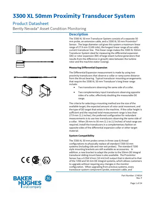
3300 XL 50mm Proximity Transducer System Product DatasheetBently Nevada* Asset Condition MonitoringDescriptionThe 3300 XL 50 mm Transducer System consists of a separate 50mm probe, an extension cable, and a 3300 XL 50 mm Proximitor*Sensor. The large diameter coil gives this system a maximum linearrange of 27.9 mm (1100 mils), the longest linear range of our eddycurrent transducer line. This linear range makes the 3300 XL 50mmTransducer System ideal for measuring the differential expansion(DE) or rotor expansion (RX) of large steam turbine generators thatresults from the difference in growth rates between the turbinerotor and the machine stator (casing).Measuring Differential ExpansionThe Differential Expansion measurement is made by using twoproximity transducers that observe a collar or ramp some distancefrom the thrust bearing. Typical transducer mounting arrangementsthat require the 3300 XL 50 mm Transducer’s long linear rangeinclude:•Two transducers observing the same side of a collar.•Two complementary input transducers observing oppositesides of a collar, effectively doubling the measurable DErange.The criteria for selecting a mounting method are the size of theavailable target, the expected amount of rotor axial movement, andthe type of DE target that exists in the machine. If the collar height issufficient and the required total measurement range is less than27.9 mm (1.1 inches), the preferred configuration for redundantmeasurements is to use two transducers observing the same side ofa collar. When 28 mm to 56 mm (1.1 to 2.2 inches) of total range arerequired, install the transducers in a complementary fashion onopposite sides of the differential expansion collar or other targetmaterial.System CompatibilityThe 3300 XL 50 mm probe comes in three case & threadconfigurations to physically replace all standard 7200 50 mmsystems (including side and rear exit probes). The standard 7200style mounting brackets are still available as accessories. Inaddition, a new bracket to adapt the probe to the 50mm DE Integraltransducer sliding mount base is also available. The ProximitorSensor has a 0.394 V/mm (10 mV/mil) output that is identical to thatof the 7200 and 50 mm DE Integral systems, which allows customersto upgrade without requiring any changes in the monitorconfiguration. When upgrading from previous systems, everytransducer system component (probe, extension cable, andPart Number: 174014Rev: FProximitor Sensor) must be replaced with 3300 XL 50 mm components.Proximity Probe and Extension CableThe 3300 XL 50 mm probe is designed to survive the harshest steam turbine DE environments. It can continually operate and maintain its accuracy in high temperatures up to 200 ︒C (392 ︒F), and can withstand intermittent high temperatures up to 250 ︒C (482 ︒F). The 50 mm probe has both a front and rear seal which, combined with the High Temperature FluidLoc* cable (standard on all 50 mm probes), prevent moisture from entering the probe tip. Special high-temperature ClickLoc* connectors are also standard on the probe and extension cable. Each probe and cable comes with connector protectors and a disposable connector protector installation tool to ensure that the connectors remain free of contamination. The ClickLoc connector on the probe lead features a removable collar that facilitates routing the cable through tight clearances.The 3300 XL 50 mm probe is available in straight exit case styles with ½-20 English threads or M14x1.5 metric threads, including a locknut with predrilled safety wire holes. The side exit probe has two ¼-20 mounting holes in the rear of the probe case. For both straight exit and side exit probes the overall case diameter is 1.99 inches.Proximitor SensorThe 3300 XL 50 mm Proximitor Sensor1 has the same advanced features as all 3300 XL Proximitor Sensors. Its thin design allows it to be mounted in either a high-density DIN-rail installation or a more traditional panel mount configuration. Improved RFI/EMI immunity allows the 3300 XL Proximitor Sensor to achieve European CE mark approvals without any special mounting considerations. This RFI immunity prevents the transducer system from being adversely affected by nearby high frequency radio signals. SpringLoc terminal strips on the Proximitor Sensor require no special installation tools and facilitate faster, highly robust field wiring connections.Notes:Proximitor Sensors are supplied by default from the factory calibrated to AISI 4140 steel. Calibration to other target materials is available upon request. Mounting AccessoriesThe correct operation of the transducer system must be initially verified during installation and periodically thereafter. This is done by physically moving the transducer to simulate the motion of the shaft collar. This requires a mounting bracket that allows the transducer system to slide relative to the shaft rotor and collar.An optional Sliding Bracket can be ordered for the 3300 XL 50 mm Transducer for both single transducer and complementary input applications. This mounting bracket allows you to verify the transducer system and gap the probes by sliding the transducer system through its linear range. The base plate of the sliding bracket is installed on the inner surface of the turbine case near the differential expansion collar. Probes are installed in the probe clamp that attaches to the sliding carriage. The sliding carriage slides onto and is secured to the base plate with bolts and safety wire. To verify and install the transducer, loosen the bolts securing the sliding carriage to the base plate and move the sliding carriage and probes. A verification kit with spindle micrometer can be temporarily secured to the base plate to provide a reference for axial verification measurements. The spindle micrometer measures the movement of the transducer system relative to the collar during these verification tests. SpecificationsUnless otherwise noted, the following specifications are for a 3300 XL 50 mm Proximitor Sensor, extension cable and probe between 0︒C and +45︒C (+32︒F to +113︒F), with a -24 Vdc power supply, a 10 kΩ load, a Bently Nevada supplied AISI 4140 steel target that is 102 mm (4.0 in) diameter or larger. The system accuracy and interchangeability specifications do not apply when using a transducer system calibrated to any target other than a Bently Nevada AISI 4140 steel target.ElectricalProximitorSensor InputAccepts one non-contacting 3300XL 50 mm Proximity Probe andExtension Cable.PowerRequires -17.5 Vdc to -26 Vdcwithout barriers at 12 mAmaximum consumption, -23 Vdcto -26 Vdc with barriers.Operation at a more positivevoltage than -23.5 Vdc can resultin reduced linear range.Outputresistance50Extension cablecapacitance:69.9 pF/m (21.3 pF/ft) typical Field wiring:0.2 to 1.5 mm2(16 to 24 AWG)Recommend using three-conductor shielded triad cable. Linear Range:27.9 mm (1100 mils). Linear rangebegins at approximately 1.3 mm(50 mils) from target and is from1.3 to 29.2 mm (50 to 1150 mils)(approximately –1.5 to –12.5 Vdc). Average ScaleFactor (ASF)394 mV/mm (10 mV/mil) nominal Deviation frombest fit straightline (DSL)Less than ±0.74 mm (±29 mils) Systemperformanceover extendedtemperatures:Over a probe temperature rangeof -35°C to +120°C (-31°F to+248°F) with the ProximitorSensor and extension cablebetween 0°C to +45°C (+32°F to+113°F), the DSL remains within±2.03 mm (±80 mils).Over a Proximitor Sensor andextension cable temperaturerange of -35°C to +65°C (-31°F to+149°F) with the probe between0°C to +45°C (+32°F to +113°F),the DSL remains within ±2.03 mm(±80 mils). RecommendedMinimumTarget Size:102 mm (4.0 in) diameter (flattarget)Compliance and Certifications Note: This device complies with part 15 of the FCC Rules. Operation is subject to the following two conditions: (1) This device may not cause harmful interference, and (2) This device must accept any interference received, including interference that may cause undesired operation.EMCEuropean Community Directives:EMC Directive 2014/30/EUStandards:EN61000-6-2EN61000-6-4RoHSEuropean Community Directives:RoHS Directive 2011/65/EU MaritimeABS 2009 Steel Vessels Rules1-1-4/7.7, 4-8-3/1.11.1, 4-9-7/13Hazardous Area ApprovalsFor the detailed listing of country and product specific approvals, refer to the Approvals Quick Reference Guide , document 108M1756, at .CSA/NRTL/C3300 XL Proximitor Sensor ia:Class I, Zone 0: AEx/Ex ia IIC T4/T5 Ga; Class I, Groups A, B, C, and D,Class II, Groups E, F and G, Class III;When installed with intrinsically safe zener barriers per drawing 141092 or when installed with galvanic isolators.nA, ec:Class I, Zone 2: AEx/Ex nA IIC T4/T5 Gc; Class I, Division 2, Groups A, B, C, and D;Class I, Zone 2: AEx/Ex ec llC T4/T5 Gc; Class I, Division 2, Groups A, B, C, and D; When installed without barriers per drawing 140979. T5 @ Ta= -55 ˚C to +85 ˚C.T4 @ Ta= -55 ˚C to +100˚C.3300 XL Probe ia:Class I, Zone 0: AEx/Ex ia IIC T5…T1 Ga; Class I, Groups A, B, C, and D,Class II, Groups E, F and G,Class III;When installed with intrinsically safezener barriers per drawing 141092 orwhen installed with galvanic isolators. (see Table 1: Temperature Schedule)nA, ec:Class I, Zone 2: AEx/Ex nA IIC T5…T1 Gc; Class I, Division 2, Groups A, B, C, and D;Class I , Zone 2: AEx/Ex ec llC T5…T1 Gc; Class I, Division 2, Groups A, B, C, and D;When installed without barriers per drawing 140979. (see Table 1: Temperature Schedule)ATEX/IECEx3300 XL Proximitor Sensor ia:II 1 GEx ia IIC T4/T5 Ga Ui= -28V Uo= -28V Ii= 140mA Io= 140mA Pi= 0.91W Po= 0.742W Ci- 47nF Co= 1.5nF Li= 1460µH Lo= 610µH nA,ec: II 3 GEx nA IIC T4/T5 GcEx ec llC T4/T5 Gc Ui= -28V li= 140 mAT5 @ Ta= -55˚ C to +85 ˚C T4 @ Ta= -55 ˚C to +100 ˚C 3300 XL ProbeNote: Probe entity parameters are met when used with BN extension cables and connected to BN Prox.ia: II 1 GEx ia IIC T5…T1 Ga, (see Table 1: Temperature Schedule) Ui = -28V Ci = 1.5 nF Ii = 140 mA Li =610 µHPi = 0.91 WnA, ec:II 3 GEx nA IIC T5…T1 Gc,Ex ec llC T5…T1 Gc,(see Table 1: Temperature Schedule).Ui = -28V li= 140 mA Table 1: Temperature ScheduleTemperature Classification Ambient Temperature (Probe Only)T1 -55ºC to +232ºCT2 -55ºC to +177ºCT3 -55ºC to +120ºCT4 -55ºC to +80ºCT5 -55ºC to +40ºC Hazardous Area Conditions of Safe Use: CSA/NRTL/C:ia:Install per Bently Nevada drawing 141092.nA, ec:Install per Bently Nevada drawing 140979. ATEX/IECEx:ia:Install per Bently Nevada drawing 141092.nA, ec :The Prox must be installed so IBas to providethe terminals with a degree of protection ofat least IP54.MechanicalProbe TipMaterial:Polyphenylene Sulfide (PPS). Probe CaseMaterial:AISI 304 stainless steel (SST). Probe CableSpecifications:75 Ω triaxial,perfluoroalkoxyethylene (PFA)insulated FluidLoc probe cable inthe following total probe lengths:1, 5 or 9 metres.Extension CableMaterial:75 Ω triaxial,perfluoroalkoxyethylene (PFA)insulated FluidLoc cable. ProximitorSensorMaterial:A380 aluminumSliding BracketMaterial:Anodized aluminum and stainlesssteelSystem Length:5 or 9 metres including extensioncableProbe andExtension CableArmor(optional):Flexible SST with PFA outer jacket. TensileStrength(maximumrated):330 N (75 pounds) probe case toprobe lead. 270 N (60 pounds) atprobe lead to extension cableconnectors.Connector material:Gold-plated brass and gold-platedberyllium copperTorque SpecificationsConnector-to-connector torque Recommendedtorque:Finger tightMaximumtorque:0.565 N•m (5 in•lb)Minimum BendRadius (with orwithout sstarmor):25.4 mm (1.0 in) Environmental LimitsProbe Temperature RangeOperatingand StorageTemperature:-35°C to +200°C (-31°F to +392°F) Short-termOperatingand StorageTemperature:+250°C (+482°F) for less than 24hours.Extension Cable TemperatureRangeOperatingand StorageTemperature:-51°C to +200°C (-31°F to +392°F) Proximitor Sensor TemperatureRangeOperatingTemperature:-51°C to +100°C (-60°F to +212°F) StorageTemperature:-51°C to +105°C (-60°F to +221°F) Sliding Bracket TemperatureRangeOperatingand StorageTemperature:-35°C to +200°C (-31°F to +392°F) RelativeHumidity:Less than a 3% change in AverageScale Factor (ASF) when tested inaccordance with IEC standard 68-2-66.Probe Pressure:3300 XL probes are designed toseal differential pressure betweenthe probe tip and case. The probeis sealed with Viton® O-rings.Probes are not pressure testedprior to shipment. Contact ourcustom design department if yourequire a test of the pressure sealfor your applicationNote: It is the responsibility of thecustomer or user to ensure that all liquidsand gases are contained and safelycontrolled should leakage occur from aproximity probe. In addition, solutionswith high or low pH values may erode thetip assembly of the probe causing medialeakage into surrounding areas. BentlyNevada will not be held responsible for anydamages resulting from leaking 3300 XLproximity probes. In addition, 3300 XLproximity probes will not be replacedunder the service plan due to probeleakage.Patents:5,685,8846,293,0056,643,9097,239,133Components or procedures described in these patents apply to this product.Ordering InformationFor the detailed listing of country and product specific approvals, refer to the Approvals Quick Reference Guide, document 108M1756, at3300 XL 50 mm Proximity Probe: 330876-AXX-BXX-CXX-DXXA:Probe Case Type Option0 1 ½-20 Thread - Straight Exit0 2 M14x1.5 Thread - Straight Exit0 3Smooth 1.99 in dia - Side ExitB:Total Length Option1 0 1.0 metre (3.3 feet)5 0 5.0 metres (16.4 feet)9 0 9.0 metres (29.5 feet)Note: Five meter probes are designed for use with thefive meter Proximitor Sensor only..C: Armor Option0 0High Temperature FluidLoc Cable0 1High Temperature FluidLoc Cablewith ArmorD: Agency Approval Option0 0 No Approvals0 5Multiple Approvals3300 XL 50 mm Proximitor Sensor 330878-AXX-BXXA:Total Length and Mounting Option5 0 5.0 metres (16.4 feet) system length,panel mount5 1 5.0 metres (16.4 feet) system length,DIN mount9 09.0 metres (29.5 feet) system length,panel mount9 19.0 metres (29.5 feet) system length,DIN mountB:Agency Approval Option0 0 No Approvals0 5Multiple Approvals3300 XL 50 mm Extension Cable 330877-AXXX-BXX-CXXNote: Make sure that the extension cable length andthe probe length, when added together, equal theProximitor Sensor total length.A:Cable Length Option0 4 0 4.0 metres (13.1 feet)0 8 08.0 metres (26.2 feet) B:Armor and Cable Option3 6FluidLoc ext cable3 7FluidLoc ext. cable w/ armorC:Agency Approval Option0 0 No Approvals0 5 Multiple ApprovalsMounting BracketsEach Sliding Mounting Bracket comes with•One sliding plate•One base plate•Sliding plate securing bolts withsafety wire holes•Lock washersThe material used for the mounting bracketsis T6061-T6 aluminum. Base platesecuring bolts are not provided;recommended bolt size is 3/8in or M8socket head bolts.3300 XL 50 mm Sliding Probe Bracket and Clamp:330879-AXX-BXXA: Probe Clamp Style0 1 Left Exit0 2 Right Exit0 3 Two clamps (used for CIDEapplications)1B: DE Mounting Bracket0 0 No Mounting Bracket; Clamp Only0 1 Single DE Mounting Bracket20 2 Short CIDE Mounting Bracket30 3 Long CIDE Mounting Bracket3This bracket is recommended for most installations. While any probe may be used, the smooth side exit probe is most often used with this bracket.1.When ordering two clamps, one right exit andone left exit clamp will be provided so that thecables exit from the same side of the CIDEbracket.2.The B01 probe mounting bracket option is onlyavailable with the A01 or A02 probe clamp styleoptions.3.The B02 and B03 probe mounting bracket optionsare only available with the A03 probe clamp styleoptions.4.When replacing 50mm DE 130713, part number330879-AA-00 should be ordered. Ordering withBB=00 will prevent unnecessary parts from beingordered with the clamp.Sliding Mounting Brackets without clamps 131071-01Single TransducerMounting Bracket 131030-01Short ComplementaryInput DifferentialExpansion (CIDE) MountingBracket131031-01Long Complementary InputDifferential Expansion(CIDE) Mounting BracketNon-sliding Mounting Brackets167285Kit, 50 mm Clamp Mount(used with smooth-caseside exit or threadedstraight exit probes). 167286Kit, 50 mm Bolt Mount(used only with smooth-case side exit probes).Verification KitsEach verification kit comes with:• a verification kit bracket• a spindle micrometer with either 0 to 2 in or0 to 50 mm range•two set screws• a bracket securing boltThe material used for the verification kit bracket isT6061-T6 aluminum.131036-01Verification Kit, SpindleMicrometer with EnglishUnits131036-02Verification Kit, SpindleMicrometer with MetricUnits Accessories173959Manual148722-013300 XL Test Plug. The 3300 XLTest Plug has three self-containedtest pins attached to three color-coded wires 1 metre in length,each terminated in a banana plug.The three-pin adapter plugs intothe test pin holes on 3300 XL-style Proximitor Sensors. It is usedto check the performance of theProximitor Sensor from the testpin holes in the terminal stripwithout requiring the removal ofthe field wiring.Extended Range Micrometer KitThe extended range micrometer kit contains a precision micrometer and a 100 mm (4 inch) AISI 4140 target and is intended for acceptance testing of Bently Nevada extended range transducers. Bracket options are available to hold 8mm – 50mm probes as well as the 50 mm Integral DE transducer.330187-AXX-BXXA:Probe options0 1 8 mm to 50 mm probe threaded orsmooth cases0 38 mm to 50 mm probe threaded orsmooth cases and an adapter for 50mm Integral DE probesB:Micrometer Option0 1 Standard English 0-2 inch micrometer0 2Standard metric 0-50 mmmicrometer02120015Bulk field wire. 1.0 mm2 (18 AWG),3 conductor, twisted, shieldedcable with drain wire. Specifylength in feet.02173009Bulk field wire. 1.0 mm2 (18 AWG),3 conductor, twisted, shieldedcable. Specify length in feet.138492-01Replacement panel-mountmounting pad138493-01Replacement DIN-mountmounting pad043103103300 XL Proximitor SensorPanel-mount Screws. Packageincludes four 6-32 UNC threadforming mounting screws(Supplied standard with 3300 XLProximitor Housings [3300 XLoption]).03200006Silicone self-fusing tape. A 9.1metre (10 yard) roll of siliconetape to protect connectors. It iseasy to install and providesexcellent electrical isolation andprotection from the environment.It is not recommended for useinside the casing of the machine. 40180-02Connector Protectors. Packagecontains 10 pairs of connectorprotectors.03839410Male Connector Protector.Placed on the extension cable toconnect to the female connectorprotector on the probe andprovide environmental protectionof connectors.03839420Female Connector Protector.Placed on the probe lead toconnect to the male connectorprotector on the extension cableand provide environmentalprotection of connectors. Alsoplaced on the extension cable toslide over the Proximitor Sensorconnection and protect it fromthe environment.330153-103300 XL 50 mm Connector Kit.Used on 3300 XL 50 mm probesand extension cables. Containsone male (removable nut) andfemale ClickLoc connectors, color-coded sleeves and two pieces slitPFA tubing.163356Connector Crimp Tool Kit.Includes one set of multi-connector inserts and connectorinstallation instructions. Suppliedwith carrying case.173873High Temperature Cable Zip-Ties. PEEK cable tie is rated foruse up to 200 C continuoustemperature. Available in bags of50 zip ties.174804-01Side Exit Probe Adapter Kit.Used to adapt side exit probes forthe 330187 Extended RangeVerification Kit.Graphs and Dimensional Drawings…Note: All dimensions on figures are in millimeters (inches) unless otherwise specified.Figure 1: Typical 3300 XL 50 mm 5 m System Over Ambient Testing RangeFigure 2: Typical 3300 XL 50 mm 9 m System Over Ambient Testing RangeFigure 3: Typical 3300 XL 50 mm Probe + 1m Cable @ Low Temperature (Proximitor Sensor+ 8m of Extension Cable @ 25 C)Figure 4: Typical 3300 XL 50 mm Probe + 1m Cable @ High Temperature (Proximitor Sensor+ 8m of Extension Cable @ 25 C)Figure 5: Typical 3300 XL 50 mm 5 m Proximitor Sensor with 4 m of Extension Cable @ ColdTemperature (Probe is at 25 C)Figure 6: Typical 3300 XL 50 mm 5 m Proximitor Sensor with 4 m Extension Cable @ HighTemperature (Probe is at 25 C)Figure 7: Typical 3300 XL 50 mm 9 m Proximitor Sensor with 8 m of Extension Cable @ LowTemperature (Probe is at 25 C)Figure 8: Typical 3300 XL 50 mm 9 m Proximitor with 8 m of Extension Cable @ HighTemperature (Probe is at 25 C.)(1) Shaft to side of probe distance.(2) Collar Height.Figure 9: Recommended Probe Position Based on Collar Height1.62.2 mm (2.45 in) maximum diameter2.3/4-in or 21 mm diameter jam nut with safety wire holes3.Case thread4.FluidLoc coaxial cable with PFA Jacket, 3.94 mm (0.155 in) maximum diameter.5.Miniature male coaxial connector, 8.0 mm (0.32 in) maximum diameter.6.Optional Stainless steel armor with PFA jacket, 9.58 mm (0.377 in) maximum diameter; 12.7 mm (0.50 in)maximum diameter of armored ferrule.Figure 10: 330876, 3300 XL 50 mm Proximity Probe, Straight Exit1.50.5 mm (1.99 in) diameter2.FluidLoc coaxial cable with PFA Jacket,3.94 mm (0.155 in) maximum diameter.3.Miniature male coaxial connector, 8.0 mm (0.32 in) maximum diameter.Figure 11: 330876, 3300 XL 50 mm Proximity Probe, Smooth 1.99 Inch Dia. Side Exit Case1.Cable length +20%, -0%2.Miniature male coaxial connector, 7.2 mm (0.29 in) maximum diameter3.Customer shrink tubing, 84 mm (3.3 in), 2 places4.Optional stainless steel armor with PFA jacket, 7.65 mm (0.301 in) maximum diameter; 10.12 mm (0.0400in) maximum diameter of armored ferrule.5.FluidLoc coaxial cable with PFA Jacket, 3.94 mm (0.155 in) maximum diameter6.Miniature female coaxial connector,7.24 mm (0.285 in) maximum diameter7.Armor Length = Cable Length – 300 mm (11.8 in)Figure 12: 330877, 3300 XL 50 mm Extension Cable5.1(0.20)Mounting Option “A” –50 or -90Figure 13: 330878 Panel Mount 3300 XL 50 mm Proximitor Sensor1.Mounting option “A” –51 or –912.35mm DIN rail (not included)3.89.4 mm (3.52 in) (additional 3.05 mm (0.120 in) required to remove DIN rail) Figure 14: 330878 DIN Mount 3300 XL 50 mm Proximitor Sensor1.10(0.40) diameter through, 15 (0.61) counterbore typicalFigure 15: 131071-01 Single Transducer Mounting Bracket1.10(0.40) diameter through, 15 (0.61) counterbore typicalFigure 16: 131030-01 Short Complementary Input Differential Expansion (CIDE) MountingBracket1. 10 (0.40) diameter through, 15 (0.61) counterbore typicalFigure 17: 131031-01 Long Complementary Input Differential Expansion (CIDE) MountingBracket1.12.7 (0.5) diameter, 2 places2.9.5 (0.37) diameterFigure 18: 131036-01 and 131036-02 Verification Kit Spindle Micrometer1.Vertical adjustments in ¼” incrementsFigure 19: 330879 Probe Clamp (330879-01 Shown)NOTE: All dimensions are in millimeters (inches) unless otherwise specified.Copyright 2006-2018 Baker Hughes, a GE c ompany, LLC (“BHGE”) A ll rights reserved.* Denotes a trademark of Bently Nevada, LLC, a wholly owned subsidiary of Baker Hughes, a GE company.All product and company names are trademarks of their respective holders.Use of the trademarks does not imply any affiliation with or endorsement by the respective owners.The information contained in this document is subject to change without prior notice.1631 Bently Parkway South, Minden, Nevada USA 89423Phone: 1-775.782.3611 。
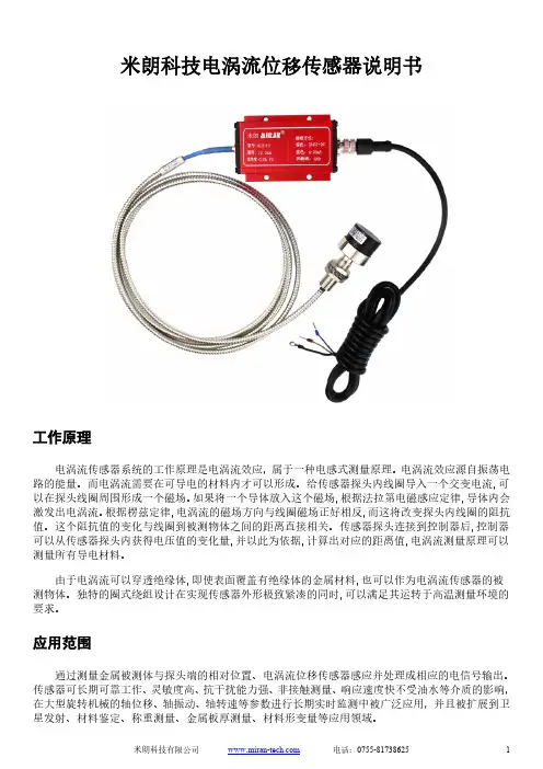
电涡流传感器系统的工作原理是电涡流效应,属于一种电感式测量原理。
电涡流效应源自振荡电路的能量。
而电涡流需要在可导电的材料内才可以形成。
给传感器探头内线圈导入一个交变电流以在探头线圈周围形成一个磁场。
如果将一个导体放入这个磁场,根据法拉第电磁感应定律激发出电涡流。
根据楞兹定律,电涡流的磁场方向与线圈磁场正好相反,而这将改变探头内线圈的阻抗性能参数测量量程1mm 2mm 4mm 5mm 12.5mm 20mm 25mm 50mm探头直径Φ6mm Φ8mm Φ11mm Φ17mm Φ30mm Φ40mm Φ50mm Φ60mm线性误差≤±0.25 ≤±0.25 ≤±0.5 ≤±0.5 ≤±1 ≤±1 ≤±1 ≤±2 (%FS)分辨率0.05um 0.1um 0.2um 0.25um 0.625um 1.0um 1.25um 2.5um重复性0.1um 0.2um 0.4um 0.5um 1.25um 2.0um 2.5um 5um频率响应0~10KHz 0~8KHz 0~2KHz 0~1KHz (-3dB)输出信号0~5V,0~10V,4~20mA,RS485电压型+9~18VDC,+18~36VDC或±15V~±18VDC可选供电电压电流型+22~30VDC,RS485型+12VDC电压型<45mA工作电流电流型<25mARS485型<40mA纹波≤20mV系统温漂≤0.05%/℃静态灵敏度根据输出信号和对应量程而定电压输出:负载能力<10KΩ输出负载电流输出:负载能力<500Ω标定时(20±5)℃环境温度探头-30℃~+150℃使用温度前置器-30℃~+85℃探头 IP67防护等级前置器 IP65探头电缆默认2m,可定制电源电缆默认2m,可定制接线定义电流型电压型RS485 棕线电源正 +24VDC 电源正 +12VDC或+24VDC 电源正 +12VDC黑线空电源负 0V 电源负 0V蓝线电流输出 OUT 输出正 OUT+ RS485 A+白线空输出负 OUT- RS485 B-屏蔽线接大地 GND 接大地 GND 接大地 GND探头典型结构图示在制作过程中,探头头部体一般采用耐高温ABS+PC工程塑料,通过“二次注塑”成型将线圈密封其中。
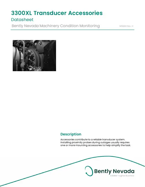
DescriptionAccessories contribute to a reliable transducer system. Installing proximity probes during outages usually requiresone or more mounting accessories to help simplify the task.3300XL Transducer AccessoriesDatasheetBently Nevada Machinery Condition Monitoring145668Rev.HThese accessories allow you to quickly and efficiently install proximity probes and route the associated cables out of the machine case. These parts also help shield the cables from electrical noise and adverse environmental conditions. Having the proper mounting hardware on-site during the probe installation saves time and money for those responsible for the project.Junction boxesJunction boxes are normally mounted on or near the exterior of a machine case and enclose electrical connections in weatherproof or explosion-proof environments. Sealtite™ flexible conduit Flexible conduit routes probe cables safely to the sensor housing and then back to the monitors. The conduit protects transducer wiring from damage that splashing liquids or accidental contact with other equipment can cause.Sealtite flexible conduit consists of a galvanized steel core with an extruded thermoplastic cover. Pipe fittings are made of steel with a zinc-plated, chromate finish and are compatible with fittings found on our watertight equipment enclosuresProbe mounting bracketsProbe mounting brackets attach internally mounted proximity probes to the machine case. S upplied mounting bolts attach the bracket to the bearing or other location inside the machine casing. The bracket holds the probe and allows for adjustment of the probe tip relative to the observed surface.For most installations, use the standard 137492 non-clamping aluminum probe bracket. When using the 137491 brackets for 3/8-inch diameter smooth case probes, tightening the bolts will compress the probe hole around the probe and lock the probe into its preset gapped position. If your application requires additional electrical isolation from the mounting location (as in some generator and electric motor bearing locations), use the 27474 phenolic probe bracket. These mounting brackets are compatible with our 3300 and 3300 XL proximity probe systems, including 5 mm, 8 mm and NSv™ probes.To ensure that the brackets screws remain fastened within the machine, secure the screws with safety wire. Each mounting bracket includes special screws with holes drilled for safety wire.Cable SealThe optional 10076 Cable Seal is mainly for use in cable routing applications. It restrains the coaxial cable from movement, prevents abrasion, and provides splash protection. One end of the cable seal has a 1/4-18 NPT thread that allows you to thread it into a 4190-36 Adapter.The cable seal has an aluminum body and an oil-resistant, slit grommet so that you can install it over armored or non-armored cable without removing the connectors. AdapterThe optional 4190 Adapter attaches a junction box to the machine case. It also allows mounting of the proximity probe in some instances.The adapter offers a variety of threads and configurations. A dapter threads and configurations that are not listed in this data sheet may be available. P lease contact your sales representative for more information. Explosion-proof fittingsExplosion-proof fittings provide seals for housings in Division 1 and in Zone 0 and 1 hazardous areas. The fittings include sealing compound, packing fiber, and the appropriate adapter. Fitting kits are available. Refer to Explosion-Proof Fittings on page 6 for details and part numbers.Low-pressure cable sealThe 43501 Low-Pressure Cable Seal provides egress for up to 4 75Ω and/or 95Ω 3300XL, 3300 and 7200 cables, or up to 2 25mm DE or 50mmDE transducer cables, through a single hole in a machine case or other barrier.The cable seal is constructed of 303 stainless steel and a molded silicon rubber grommet and prevents leakage of fluids along the outer jacket of the cable. The seal has threads on both ends and fits into a tapped hole on the machine case or barrier. External pipe threads enable the seal to mate to conduit or housings. You can use the low-pressure cable seal only with non-armored cables. Its design seals pressures up to 345 kPa (50 psi) when properly installed.High-Temperature Cable TiesThe 173873 high-temperature cable tie is an economical alternative to metal brackets in high-temperature applications. These cable ties are molded from VICTREX® PEEK™ polymer for multiple uses in extreme environments up to +180°C (+356°F).SpecificationsJunction BoxesCylindrical Junction Box P/N 03818016 ComponentsMain body and blankcoverDimensionsOverall Height76 mm (3.0 in)Body Diameter89 mm (3.5 in)Hub-to-Hub121 mm (4.75 in) Base to Hub Center16 mm (0.64 in) Fittings3/4-14 NPT5 placesMaterial AluminumOptional Extension for 03818016 P/N 03818022ComponentsMain body Dimensions (Extensiononly)Overall Height93mm (3.7 in)Body Diameter90mm (3.6 in)Hub-to-Hub (flats)91 mm (3.6 in)Total ExtendedHeight150 mm (5.90 in) Material Aluminum Rectangular Junction Box P/N 03818065 ComponentsMain body and cover Dimensions Overall Height27.9 mm (1.10 in) Width of Body38.1 mm (1.50 in) Length of Body95.3 mm (3.75 in) Fittings1/2-14 NPT2 places Material Aluminum Rectangular Junction Box P/N 03818066 ComponentsMain body and cover Dimensions Overall Height61.0 mm (2.40 in) Width of Body44.5 mm (1.75 in) Length of Body102 mm (4.00 in) Fittings3/4-14 NPT2 places Material Aluminum Sealtite Flexible Conduit Components Refer to Figure 4.Fitting Options1/2-14 NPT3/4-14 NPTLength As ordered BracketsClamp Mounting Bracket for 3/8-inch diameter smooth body probesDimensions Refer to Figure 5.Mounting Screw Thread Size Options 10-24 UNC-2A M5 x 0.8-6gMaterial AluminumNon-Clamping Mounting Bracket for threaded case probesDimensions Refer to Figure 6. Mounting Screw Thread Size10-24 UNC-2Aor M5 x 0.8-6g Material Aluminum Probe Lock NutThread Sizes 3/8-24 UNF-2B M10 x 1-6HFeatures Lock nut with holes to attachsafety wire.Cable Seal (P/N 10076) Components Refer to Figure 7Overall length (assembled)35mm (1.4 inches) in tightened conditionAdaptersFeatures Refer to Figure 8 4190-01Dimensions Internal Diameter9.53 mm (0.375 in) Internal thread type1/4-18 NPT External thread type1/2-14 NPT Overall Length38.1 mm (1.50 in) 4190-03Internal Diameter11.1 mm (0.437 in) Internal thread type1/4-18 NPT External thread type3/4-14 NPT Overall Length46.0 mm (1.81 in) 4190-04Internal Diameter7.14 mm (0.281 in) Internal thread type1/4-28 UNF-2B External thread type1/2-14 NPT Overall Length38.1 mm (1.50 in) 4190-06Internal Diameter10.3 mm (0.406 in) Internal thread type3/8-24 UNF-2B External thread type1/2-14 NPT Overall Length38.1 mm (1.50 in) 4190-16Internal Diameter10.3 mm (0.406 in) Internal thread type3/8-24 UNF-2B External thread type3/4-14 NPT Overall Length46.0 mm (1.81 in) 4190-20Internal Diameter16.7 mm (0.656 in) Internal thread type5/8-18 UNF-2B External thread type3/4-14 NPT Overall Length46.0 mm (1.81 in)4190-34Internal Diameter7.14 mm (0.281 in) Internal thread type1/4-28 UNF-2B External thread type3/4-14 NPT Overall Length56.1 mm (2.21 in) 4190-36Internal Diameter10.3 mm (0.406 in) Internal thread type1/4-18 NPT3/8-24 UNF-2B External thread type3/4-14 NPT Overall Length56.1 mm (2.21 in) Material304 Stainless Steel Explosion-Proof Fittings29368-01 Optional Fitting KitKit contains the following:03818056Hazardous area ¾” sealing fitting,conduit04576120 4 OZ adhesive sealant20892-02fiber seal03839246.750” aluminum plug72340 Fitting KitKit contains the following:03839246.750” aluminum plug 038500213/4 to 1/2 reducer thread fitting 49871-01cable grip assembly 03839153grommet sealing 250-312 ring 03839154grommet sealing 312-375 ring 20892-02fiber seal038180563/4 conduit fitting 03839155ring cable fitting 045761278 OZ adhesive sealant 04576120 4 OZ adhesive sealant 04760000string tag labelFeaturesRefer to Figure 9.Dimensions03818055Conduit size1/2-14 NPT Overall Length69.9 mm (2.75 in) Width49.3 mm (1.94 in) Min. turn radius63.5 mm (2.50 in) 03818056Conduit size3/4-14 NPT Overall Length69.9 mm (2.75 in) Width49.3 mm (1.94 in) Min. turn radius63.5 mm (2.50 in) 03818058Conduit size1-1/4 NPT Overall Length102 mm (4.00 in) Width54.1 mm (2.13 in) Min. turn radius57.2 mm (2.25 in) Material AluminumLow Pressure Cable SealDimensions Refer to Figure 10 Fitting Options1/2-14 NPT3/4-14 NPTHigh Temperature Cable TiesTemperature Up to +180°C (+356°F)Material VICTREX PEEK polymerOrdering InformationFor the detailed listing of country and product specific approvals, refer to the Approvals Quick Reference Guide (108M1756) available from .Sealtite Flexible Conduit3/4-14 NPT assembly Minimum length: 1 foot Maximum length: 99 feet Example: 0 1 = 1 foot9 9 = 99 feetAluminum Clamp Mounting Bracket for 3/8-inch Diameter Smooth Body Probes137491-AXXAluminum Non-ClampingMounting Bracket for Threaded Case Probes137492-AXXThe -0 1 and –0 2 option are supplied with two 10-24 UNC-2A mounting screws with safety wire holes. The -0 3 and -0 4 options are supplied with two M5 x 0.8-6g mounting screws with safety wireholes.Phenolic Mounting Bracket27474-AXXThe -0 1 and -0 2 options are supplied with two 10-24 UNC-2A mounting screws with safety wire holes. The -0 3 and -0 4 options are supplied with two M5 x 0.8-6g mounting screws with safety wire holes. The dimensions are identical to the aluminum mounting bracket 137492.Cable Seal10076-AXX0 150 Ω, without armor0275/95 Ω, without armor0 375/95 Ω, with armor0 450 Ω, with armorAdapter4190-AXXXX See Specifications section for dimension details.Additional sizes and configurationsavailable in both standard product andspecial modifications. Contact yourlocal sales representative for details. Low Pressure Cable Seal43501 – AXX – BXX - CXXJunction Boxes03818016Cylindrical Junction Box. 03818022Optional Extension for CylindricalJunction Box.03818065Rectangular Junction Box.Dimensions (W x L x D) 38.1mm x95.3mm x 29.7mm (1.10in x 1.50in x3.75in x 1.10in).03818066Rectangular Junction Box.Dimensions (W x L x D) 44.5mm x102mm x 61.0mm (1.75in x 4.00in x61.0in).Explosion-Proof Fittings038180551/2-14 NPT Fitting 038180563/4-14 NPT Fitting 03818057 1 to 11½ NPT Fitting 038180581¼ to 11½ NPT FittingProbe Lock Nuts043010073/8-24 UNF-2B. 04301008M10 x 1-6H. Accessories for Low Pressure Cable Seal04490104Punch tool kit for solid grommetoption.43574-04Replacement grommet. For up to 4cables.43575-04Replacement washerField Wiring021730062-conductor, twisted, shielded 18AWG (1.0 mm2).021730083-conductor, twisted, shielded 22AWG (0.5 mm2).021730093-conductor, twisted, shielded 18AWG (1.0 mm2).Use 2-conductor cable with velocitytransducers. U se 3-conductor cablewith Proximitor Sensors and interfacemodules. Specify number of feet whenordering.High Temperature Cable Ties 173873Bag of 50 Multiple-Use VICTREX PEEK Polymer Cable ties. For extreme environments up to+180°C (+356°F). One or more sizes/quantities available(?), including 7 inches long. Electrical Isolator19094-017200 Proximitor Sensor and Interface Module Isolator. P rovides electrical isolation for the 7200 Proximitor Sensor, velocity to displacement converters, and accelerometer interface modules.Graphs and FiguresAll dimensions shown in millimeters (inches) except as noted.1. Junction Box (03818016)2. Low Pressure Cable Seal (43501-02-04-02)3. High Temperature Cable Ties (173873)4. 3300 XL 8mm Probe (330101)5. Probe Mounting Brackets (137492-01)6. Connector Protectors (40113-02)7. Flexible Conduit (14848)8. Machine Case9. Machine ShaftFigure 1: Typical Internal Mounting Arrangement for an XY Proximity Probe Application1. 1. 121 (4.75) Typ.2. 2. 89 (3.50) Dia.3. 3. 90 (3.55) Dia.Figure 2: Cylindrical Junction Box and Optional ExtensionFigure 3: Junction BoxFigure 4: Sealtite™ Flexible Conduit1. 1. 5.11 (0.201) Dia.Figure 5: Clamping Aluminum Probe Bracket1. 5.11 (0.201) Dia.Figure 6: Non-Clamping Aluminum Probe Bracket1. 3/4 Hex2. 1/4 NPTFigure 7: Cable Seal1. Internal Diameter2. Internal Thread3. External Thread4. 4. 1-1/8 HexFigure 8: 4190 Adapter - 304 stainless steel (-34 Shown)Copyright 2020 Baker Hughes Company. All rights reserved.Bently Nevada and Orbit Logo are registered trademarks of Bently Nevada, a Baker Hughes Business, in the United States and other countries. The Baker Hughes l ogo is a trademark of Baker Hughes Company. All other product and company names are trademarks of their respective holders. Use of the trademarks does not imply any affiliation with or endorsement by the respective holders.Baker Hughes provides this information on an “as is” basis for general information purposes. Baker Hughes does not make any representation as to the accuracy or completeness of the information and makes no warranties of any kind, specific, implied or oral, to the fullest extent permissible by law, including those of merchantability and fitness for a particular purpose or use. Baker Hughes hereby disclaims any and all liability for any direct, indirect, consequential or special d amages, claims for lost profits, or third party claims arising from the use of the information, whether a claim is asserted in contract, tort, or otherwise. Baker Hughes reserves the right to make changes in specifications and features shown herein, or discontinue the product described at any time without notice or obligation. Contact your Baker Hughes representative for the most current information.The information contained in this document is the property of Baker Hughes and its affiliates; and is subject to change without prior notice. It is being supplied as a service to our customers and may not be altered or its content repackaged without t he express written consent of Baker Hughes. This product or associated products may be covered by one or more patents. See /legal.1631 Bently Parkway South, Minden, Nevada USA 89423Phone: 1.775.782.3611 or 1.800.227.5514 (US only)。

电涡流位移传感器用户使用手册北京拓普瑞晟测控技术有限公司td前言本手册适用于对电子仪表以及对设备监测有实践经验的工程技术人员。
您可以通过本手册了解电涡流位移传感器系统的工作原理、系统组成、产品性能,并获得传感器安装、维修方面的有关建议。
本手册第一章综合介绍了传感器的优越性能、各部分组成结构以及传感器系统的基本工作原理和影响传感器系统工作的一些因素。
第二章介绍了对传感器系统进行验收的一般程序,以及对传感器系统最常见的三种使用方式和系统进行安装时应注意的问题提出了一些建议。
第三章介绍了传感器系统的重新校准以及故障检查和维修的方法。
本手册中有关传感器的型号规格的规定以及传感器的详细技术规范是依据美国石油部标准API670提出的。
本手册提出的一些安装传感器系统方面的建议,主要参照API670标准以及经验所得,可作您的参考之用。
若有不详之处,敬请来电来函。
目录第一章综述第一节系统简介1—3 第二节系统工作原理1—3 第三节产品说明1—4 第四节被测体尺寸与材料的影响1—7第二章使用说明第一节验收与保存2—9 第二节传感器的典型应用2—9 第三节探头的安装2—13 第四节延伸电缆的安装2—20 第五节前置器的安装2—22 第六节系统的连接2—23第三章校准与维修第一节校准3—27 第二节故障与维修3—29第一章 综 述第一节 系统简介为何采用电涡流传感器● 电涡流位移传感器能测量被测体(必须是金属导体)与探头端面的相对位置。
● 电涡流位移传感器长期工作可靠性好、灵敏度高、抗干扰能力强、非接触测量、响应速度快、不受油水等介质的影响,常被用于实时监测,可以分析出设备的工作状况和故障原因,有效地对设备进行保护及进行预测性维修。
● 从转子动力学、轴承学的理论上分析,大型旋转机械的运行状态主要取决于其核心——转轴,而电涡流位移传感器能直接测量转轴的状态,测量结果可靠、可信。
过去,对于机械的振动测量采用加速度传感器或速度传感器,通过测量机壳振动,间接地测量转轴振动,测量结果的可信度不高。

本特利轴向位移探头说明3300 XL 11mm 电涡流传感器系统对于油膜轴承机器非接触式振动和位移测量,3300 XL 11mm电涡流传感器系统可输出3.94 V/mm(100mV/mil)。
11mm的探头端部使这种传感器与我们标准的3300 XL8mm传感器系统相比具有更大的线性区。
它主要应用在要求大线性范围的下列测量:轴向(推力)位移测量蒸汽轮机的斜面差胀测量往复式压缩机活塞杆位移或下降的测量转速计和零转速测量相位参考(键相位)信号330701 3300 XL 11mm探头,1/2-20 UNF螺纹,非铠装330702 3300 XL 11mm探头,1/2-20 UNF螺纹,铠装330707 3300 XL 11mm探头,5/8-18 UNF螺纹,非铠装本特利(Bently Nevada)330707-05-35-10-02-00本特利(Bently Nevada)330707-00-62-10-01-00本特利(Bently Nevada)330707-00-20-10-02-00330708 3300 XL 11mm探头,5/8-18 UNF螺纹,铠装3300 XL 11mm 电涡流探头,公制330703 3300 XL 11mm探头,M14×1.5螺纹,非铠装本特利(Bently Nevada)330703-000-040-50-11-00本特利(Bently Nevada)330703-000-040-10-02-00本特利(Bently Nevada)330703-000-050-10-02-00本特利(Bently Nevada)330703-000-050-50-02-00本特利(Bently Nevada)330703-000-060-10-02-00本特利(Bently Nevada)330703-000-060-90-02-00本特利(Bently Nevada)330703-000-064-90-02-00本特利(Bently Nevada)330703-000-070-10-02-00本特利(Bently Nevada)330703-000-080-10-02-00本特利(Bently Nevada)330703-000-090-10-02-00本特利(Bently Nevada)330703-000-100-10-02-00本特利(Bently Nevada)330703-000-120-10-02-00本特利(Bently Nevada)330703-050-120-10-02-00330704 3300 XL 11mm探头,M14×1.5螺纹,铠装本特利(Bently Nevada)330704-000-100-10-11-00本特利(Bently Nevada)330704-000-040-10-02-00本特利(Bently Nevada)330704-000-050-10-01-05本特利(Bently Nevada)330704-000-050-10-02-00本特利(Bently Nevada)330704-000-060-10-02-00本特利(Bently Nevada)330704-000-060-90-02-00本特利(Bently Nevada)330704-000-080-10-02-00本特利(Bently Nevada)330704-000-080-50-02-00330709 3300 XL 11mm探头,M16×1.5螺纹,非铠装本特利(Bently Nevada)330709-000-030-10-02-00本特利(Bently Nevada)330709-000-040-10-02-00本特利(Bently Nevada)330709-000-040-50-02-05本特利(Bently Nevada)330709-000-050-10-02-00本特利(Bently Nevada)330709-000-060-10-02-00本特利(Bently Nevada)330709-000-060-50-02-00本特利(Bently Nevada)330709-000-060-90-02-00本特利(Bently Nevada)330709-000-070-10-02-00本特利(Bently Nevada)330709-000-080-10-02-00本特利(Bently Nevada)330709-000-120-10-02-00本特利(Bently Nevada)330709-010-070-10-02-00本特利(Bently Nevada)330709-010-130-10-02-00本特利(Bently Nevada)330709-050-120-10-02-00330710 3300 XL 11mm探头,M16×1.5螺纹,铠装本特利(Bently Nevada)330710-000-040-10-11-00本特利(Bently Nevada)330710-000-050-10-02-00本特利(Bently Nevada)330710-000-060-10-02-00本特利(Bently Nevada)330710-050-124-10-02-00本特利(Bently Nevada)330710-050-124-90-02-003300 XL 11mm 反装探头330705-02-18-CXX-DXX-EXX,3/8-24 UNF螺纹本特利(Bently Nevada)330705-02-18-10-02-00本特利(Bently Nevada)330705-02-18-90-02-00本特利(Bently Nevada)330705-02-18-90-02-05330706-005-046-CXX-DXX-EXX,M10×1螺纹本特利(Bently Nevada)330706-005-046-10-02-00本特利(Bently Nevada)330706-005-046-10-02-053300 XL 11mm前置器本特利(Bently Nevada)330780-50-00本特利(Bently Nevada)330780-50-05本特利(Bently Nevada)330780-51-00本特利(Bently Nevada)330780-90-00本特利(Bently Nevada)330780-91-00本特利(Bently Nevada)330780-91-053300 XL 11mm 延伸电缆本特利(Bently Nevada)330730-040-00-00本特利(Bently Nevada)330730-040-01-00本特利(Bently Nevada)330730-040-03-00本特利(Bently Nevada)330730-040-12-00本特利(Bently Nevada)330730-040-13-00本特利(Bently Nevada)330730-080-00-00本特利(Bently Nevada)330730-080-01-00本特利(Bently Nevada)330730-080-02-00本特利(Bently Nevada)330730-080-11-00本特利(Bently Nevada)330730-080-12-00本特利系统主要是对大型旋转设备的振动检测,测量转子和机壳的振动、速度、加速度和位移。
3300 XL 11mm 电涡流传感器系统概述传感器系统3300 XL 11 mm电涡流传感器系统由以下几部分组成:• 3300 XL 11mm探头• 3300 XL 11mm延伸电缆• 3300 XL 11mm前置器对于油膜轴承机器非接触式振动和位移测量,3300 XL 11mm 电涡流传感器系统可输出3.94 V/mm ( 100mV/mil )。
11mm的探头端部使这种传感器与我们标准的3300 XL8mm传感器系统相比具有更大的线性区。
它主要应用在要求大线性范围的下列测量:•轴向(推力)位移测量•蒸汽轮机的斜面差胀测量•往复式压缩机活塞杆位移或下降的测量•转速计和零转速测量•相位参考(键相位)信号3300 XL11 mm前置器的设计目标是取代7200系列11mm和14mm传感器系统。
当从7200系统升级到3300 XL11mm系统时,所有的部件都必须被3300 XL11mm部件替换;同时,监测系统也要升级。
如果使用3500监测系统,则需要软件组态的升级版本,该版本可以兼容3300 XL11mm系统;现存的3300监测系统也需要作相应的修改。
欲了解更多信息,可与本特利内华达公司当地的销售和服务代表联系。
应用建议:3300 XL11mm趋近式传感器系统设计用于频率范围从0到8kHz的位移或振动测量,典型应用包括径向振动和位移、轴向位移以及键相位测量。
应用注意事项:虽然前置器的终端和连接器具备静电释放保护功能,但在使用过程中还应对静电释放多加注意。
前置器3300 XL 11mm 前置器与3300 XL8mm前置器有同样的优点。
由于设计精巧,它既可以采用导轨安装,也可以采用传统的面板安装。
改进的抗辐射能力使它在安装上毋需作任何考虑就可以达到欧洲电磁兼容性标准,这一特性也可以使它免受附近各种高频无线电波的干扰。
前置器上的弹簧定位端子带使安装更方便快捷,不需要特殊的安装工具,连线也十分坚固可靠。
趋近式探头和延伸电缆3300 XL11mm探头有多种规格的探头座,包括铠装和非铠装的1/2-20、5/8- 18、 M14×1.5和M16×1.5探头螺纹,背面安装的3300 XL 11mm探头是3/8-24或M10×1的标准螺纹。

本特利电涡流传感器传感器常见问题解决方法美国BENTLY本特利电涡流传感器本特利内华达的电涡流传感器。
用于大多数涡流机械的长期监测,它们测量实际的轴运动,这是反映机器受力的牢靠指标。
3300 XL 8 mm 电涡流传感器系统:这种电涡流传感器系统供应大80 mils (2 mm)线性范围和200 mV/mil的输出。
它在大多数机械监测应用中用于径向振动、轴向(侧向)位移、转速和相位(Keyphasor )测量,并符合美国石油协会标准670第4版的要求。
有多种螺纹尺寸、探头配置和安装附件可供选择。
3300 XL 11 mm 电涡流传感器系统:这种电涡流传感器系统专门用于当我们8 mm传感器的80 mil (2 mm)线性范围不能充分要求时的场合。
11 mm 电涡流传感器系统供应大180 mils (4 mm)的线性范围和100 mV/mil的输出,紧要用于要求大线性范围的轴向(测向)位移、转速、差胀以及往复式压缩机活塞杆位置(下落)测量。
有多种螺纹尺寸、探头配置和安装附件可供选择。
3300 5mm/8mm 电涡流传感器系统:这种电涡流传感器系统是我们的3300 XL 8 mm 系统的前一代产品,我们推举在全部新的和备件应用中使用3300 XL 8 mm系统。
8 mm XL 探头、电缆和前置器和旧的 3300 系列产品具有互换性。
当8 mm探头的端部直径和相应的螺纹尺寸不适用时,也可以使用5 mm探头。
有多种螺纹尺寸、探头配置和安装附件可供选择。
3300 XL NSv 电涡流传感器系统:这种电涡流传感器系统具有5mm端部直径和60 mils (1.5 mm)的更短线性范围,适用于被测靶面区域小、侧视或沉孔间隙减小以及其它限制使用我们标准的 5 mm / 8 mm 电涡流传感器的情况。
3300 16 mm 高温电涡流传感器系统:这种电涡流传感器系统用于350℃ (662F)的高温环境,如温度超过我们标准电涡流探头和电缆能够承受的极限的某些燃气和蒸汽轮机应用。
3300系列电涡流传感器系统一.系统组成:3300电涡流趋近传感器系统是由趋近式探头、延伸电缆、前置器和信号电缆、监测器所组成。
催化装置应用在监测机组的轴振动、轴位移、转速、轴温上。
二. 工作原理电涡流传感器是通过传感器端部线圈与被测物体间的间隙变化来测量物体的振动和静位移的。
趋近式探头使用专用电缆,安全方便的连接到探头端部,能承受很大的拉力。
探头由通有高频信号的线圈构成,被测轴金属表面与探头相对位置变化时,形成的电涡流大小改变,使探头内高频信号能量损失大小变化,这个变化信号通过前置器转换成与位置变化相对应的电压信号送到监测器显示或报警。
三、前置器具有一个电子线路,它可以产生一个无线电频率信号,它能探测到能量的损耗,并能产生一个输出电压,该电压正比于所测间隙。
前置器电源的要求:无安全栅时要求-17.5--26VDC,电流最大12MA;有安保器时要求-23--26VDC。
四、电涡流探头的优点和缺点;优点:①可测量转速及相位角。
②校准很方便。
③传感器系统是一整体,其中没有相对运动部分,不会产生磨损、疲劳。
④可用于永久性检测,从所测轴的振动曲线可得到很多有用信息,可用来对机械进行故障诊断。
⑤可测量轴的振动、轴的位置以及慢速转动时轴的弯曲。
缺点:①对被测材料的成分以及表面缺陷比较敏感。
②需要外部电源。
③有时安装比较困难。
五、电涡流探头安装及校准先将配套的延伸电缆和前置放大器安装就绪,在机组不旋转时,把探头拧进安装孔,一直到探头端部接触到轴表面然后退回到1.25圈,再把探头延伸电缆以及前置器统一连接起来。
用测量前置放大器输出电压的方式调整间隙,首先供给前置器电源电压(-18--26VDC)。
在前置放大器的输出端连接一数字万用表,再调整探头直到达到零点间隙电压为止。
最后稍微拧紧紧固螺母,再利用间隙电压测量方式细调探头,使放大器输出达到零点间隙电压,最后上紧固定螺母使探头固定,小心别破坏螺纹。
一般情况下,己调整好线性范围的传感器,检测系统的零点间隙电压,调整为正常范围的中间值-9±0.25VDC。
本特利前置器
330180-50-00是本特利(bently)前置器的一种常用型号,有下列传感器系统的3300 XL 11mm ,3300 XL8mm , 3300 XL25mm, 3300 XL50mm 的前置器 ,它既可以采用紧凑的导轨安装,也可以采用传统的面板安装。
两种形式的安装基板均具有电绝缘性,不需要独立的绝缘板。
3300 XL 前置器抗无线电干扰能力强,降低了安装的复杂性。
常用型号如下:
前置器330780-50-00
前置器330780-90-00
前置器330780-50-05
前置器330780-90-05
前置器330780-51-00
前置器330780-91-00
前置器330850-50-05
前置器330850-90-05
前置器330980-50-00
前置器330980-70-00
前置器330180-51-00
前置器330180-91-00
前置器330180-91-00
前置器330180-51-05
前置器330180-91-05
前置器330180-91-05 前置器330180-50-00 前置器330180-90-00 前置器330180-90-00 前置器330180-50-05 前置器330180-90-05 前置器330180-90-05 前置器330878-50-00 前置器330878-90-00。
TSI学习总结I TSI 学习总结- -陈恒伟8月24至27日,我参加了山东电力研究院举办的汽轮机监视系统(TSI)培训班, 在这次培训中以3500为例主要学习了TSI监视系统功能原理及TSI系统安装、组态和维护;TSI系统故障诊断和与电厂的其它设备如DCS系统、状态检修系统等接口的工作原理。
汽轮机监视仪表(TSI)是一种可靠的多通道监视仪表,能连续不断的测量汽轮发电机组转子和汽缸的机械运行参数,先是机器的运行状况;提供输出信号给记录仪;并在超过设定的运行极限时发出报警。
另外还能提供跳机保护信号以及可用于故障诊断的测量。
TSI系统包括3500监视系列仪表框架和带有导线的传感器。
传感器包括线性位移变换器(LVDT)和连接于前置器的探头。
前置器安装在探头附近,并通过现场屏蔽电缆连接到相应的框架信号组件。
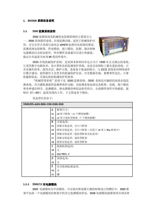
一、3500 系统概述3500系统提供连续、在线监测功能,适用于机械保护应用,并完全符合美国石油协会API670标准对该类系统的要求。
它是本特利内华达采用传统框架形式的系统中功能最强、最灵活的系统,具有其它系统所不具备的多种性能和先进功能。
该系统系统高度模块化的设计包括:1.3500/05仪表框架:全尺寸3500框架可采用19”EIA导轨安装、面板安装或壁板安装形式。
框架最左端是专为两个电源模块和一个框架接口模块预留的位置,框架中的其余14个插槽可以被任意模块组合所占用。
所有模块插入到框架的底板中,由前面板部分和框架后部相应的I/O模块组成。
2.一个或两个3500/15电源:3500/15有交流和直流两种形式,框架中可使用单电源右当电源不允许中断时使用冗余双电源。
每个电源可以单独为整个框架及其模块供电。
此模块具有自检功能,可以监测是否所有的输出电压符合规范,并通过模块前面板上的绿色“Supply OK”发光二极管显示出来。
3.3500/20框架接口模块:框架接口模块(RIM)是3500框架与组态、显示和状态监测软件连接的主要接口。