HY-MS系列交流不间断电源系统使用说明书
- 格式:doc
- 大小:3.67 MB
- 文档页数:17
目录重要安全注意事项 (3)1.禁止事项 (3)2.使用注意事项 (4)第1章产品介绍 (5)1.1 MS系列一般特性说明 (5)1.2 MS系列特殊功能说明 (5)第2章面板及背板功能说明 (6)2.1 面板指示说明 (6)2.2 背板功能说明 (8)2.3 通讯接口 (11)第3章安装及操作说明 (12)3.1 UPS拆装 (12)3.2 选择适当安装位置 (12)3.3 安装与操作测试 (13)3.4 储存注意事项 (13)3.5 SNMP 扩充槽 (14)第4章UPS工作状态说明 (16)4.1 市电正常时UPS工作回路 (16)4.2 市电异常UPS工作回路 (17)4.3 过载时 (17)4.4 逆变器故障时UPS工作回路 (18)4.5 逆变器温度过高时 (18)4.6 逆变器电流异常及其输出电压异常时 (18)第5章基本故障排除 (19)5.1 系统方块图 (19)5.2 故障判定及排除 (19)5.3 保存养护 (20)第6章软件安装 (21)6.1 硬件安装 (21)6.2 软件安装(安装完毕后请重新启动系统) (21)第7章附录 (23)7.1 规格表 (23)重要安全注意事项1. 禁止事项1. 本产品非本公司或授权经销商之技术人员,请勿擅自开启机壳,否则您的保证将会失效,且有触电的危险。
2. 产品内所有零件皆经检查及合乎高标准规格,未经授权之经销商或检定合格专业人员及使用者,请勿自行修护及更换零件。
3. UPS本体的上方禁止放置花瓶或装水容器,花瓶或装水容器倾倒会导致水份进入机器内,容易产生触电、UPS内部损坏之危险。
4. 本产品禁止使用于有火花、烟雾、瓦斯等现象之环境,以免导致跳火(ARC)、受伤、火灾之危险。
2. 使用注意事项1. 本产品的使用环境及保存方法,对产品的使用寿命,及故障发生有绝对的影响。
因此,请特别注意避免下列工作环境使用:a. 避免在使用说明书内所记载以外(温度0-40O C,相对湿度30-90%),之高温、低温、潮湿场所使用。
不间断电源使用说明(一)不间断电源使用说明一、产品简介•不间断电源是一种电气设备,它能在电网供电中断时提供稳定的电能,以保护设备免受电力波动的影响。
二、使用注意事项1.安全性–在使用不间断电源时,务必确保设备接地良好,以避免电击风险。
–避免与水源接触,防止发生漏电事故。
2.环境–不间断电源应放置在通风良好的地方,远离潮湿和高温环境,以延长设备寿命。
–避免阳光直射,保持设备表面干净。
3.接线–接线前务必关闭不间断电源开关,并确保电源线插头与设备接口连接牢固。
–不要长时间拉扯电源线,避免引起短路或线松动。
4.负载–不间断电源具有一定的输出功率限制,请确保接入的设备不超过其额定负载。
–长时间超负荷使用可能导致不间断电源过热或损坏。
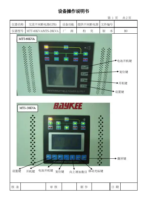
三、工作状态指示•不间断电源通常具有LED指示灯,用以显示设备的工作状态。
•常见指示灯含义:–电池状态:绿灯表示正常,红灯表示需要更换电池。
–市电状态:绿灯表示正常供电,红灯表示市电中断。
–故障状态:黄灯表示设备故障,应及时联系维修人员。
四、故障排除•在使用过程中,如果发生以下情况,请按以下步骤进行故障排查:1.电源无法开启:–检查电源线是否接触牢固,插头和插座是否正常工作。
–检查电池是否已完全充电。
–如仍无法解决,请联系维修人员。
2.设备无法正常工作:–检查负载是否超过不间断电源额定负载。
–检查市电是否正常供电,电源是否处于市电模式。
–如仍无法解决,请联系维修人员。
五、维护保养1.定期检查–建议定期检查不间断电源的电池状态,确保其正常工作。
–定期清洁设备表面,保持通风良好。
2.电池更换–根据不间断电源使用说明书,定期更换电池,以确保电源持续稳定供电。
六、免责声明•我们对于用户在使用不间断电源过程中可能发生的人身伤害、财产损失等情况,不承担任何责任。
•用户在使用前,请仔细阅读本说明书并按照要求操作,以保障安全。
以上就是不间断电源使用说明,希望对您有所帮助!如有任何问题,请随时联系我们。

HYS-45kVA 消防设备应急电源使用说明书武汉帕沃电源设备制造有限公司一、前言承蒙您选用HYS系列FEPS消防设备应急电源。
在使用FEPS消防设备应急电源前请详细阅读本使用说明书,以便正确使用FEPS消防设备应急电源,充分发挥其功能,并确保安全。
请永久保存此说明书,以便日后保养、维护、检修时使用。
FEPS消防设备应急电源乃电气类产品,为了您的安全,请务必由专业电气工程人员安装、调试。
若有疑虑,请联络本公司各地办事处或代理商恰询,我们的专业人员乐于为您服务。
本说明书如有变动,恕不另行通知。
二、 FEPS概述FEPS消防设备应急电源是专门为消防设备和专用负荷或照明用电而设计。
在交流电网正常时,由交流电网经过本设备内互投装置直接给负载供电,同时本设备内充电器给电池组进行智能充电。
当交流电网断电或电网电压低于±25%额定值时,本设备将立即投切至逆变输出供电,由电池组备用电经过逆变,继续给负载提供正弦波交流电。
当电网电压正常后,本设备将恢复至电网供电。
为适应消防应急时对电源的需求,本设备设有手动故障复位开关、电池组欠压保护强制应急开关。
三、 HYS型系列FEPS主要电气性能容量45kVA充电器输入市电AC380V±25% 50Hz+2% 充电电压DC4272V充电电流1-5 A充电方式均充、浮充自动切换蓄电池电池种类铅酸免维护电池额定电压DC372V备用时间 90min(可以根据需要配备蓄电池) 充电时间≤24h应急逆变输出电压AC380V±3% 50Hz±2.5Hz 输出波形正弦波THD≤5%(阻性)过载能力120% 声光报警、150% 切断输出保护功能过载、开路、欠压(可解除)保护应急切换<5S(重要场所小于0.25S)工作环境 噪 音应急时≤50dB 相对湿度 0~90% 不结露 环境温度 -25℃~40℃ 海拔高度<2500m四、 HYS 型系列FEPS 产品特点1. 数字芯片(DSP )32位微处理器控制,SPWM 调制技术,功能齐全2. 进口IPM 智能功率模块,输出平衡、稳定。

2020年逆变器说明全厂不间断电源精品版OYAMA使用说明书USER’S MANUAL INVERTER POWER SUPPLY目录使用手册第1页1.简介1.1.概述1.2.注意事项2.外形结构2.1 1KVA INV外观.2.2 2、3KVA INV外观2.3 5、6KVA INV外观(2﹑3KVA INV标机外观)2.4 8KVA-20KVA INV外观3、INV的放置3.1.搬运或移动3.2.放置4、INV的安装及接线4.1.注意事项4.2.单机INV安装4.2.1 1KVA INV4.2.2 2KVA以上INV4.3.备份INV安装4.4三相INV安装4.5动力配件选择4.5.1配线选择4.5.2空气开关选择5.INV的选择5.1控制及指示装置5.2操作程序5.2.1第一次开机5.2.2存放步骤5.2.3关机程序5.2.4开机程序5.2.5断电情况6.状况处理6.1运转指示6.2异常处理程序7.INV工作原理7.1正常7.2断电7.3备用电源供电7.4 备份INV运作7.4.1正常工作7.4.2备机工作8.INV及电池之保养8.1INV之保养8.2电池之保养9.通信介面说明10.电气规范10.1单相电气规范10.2三相电气规范1.简介1.1概述本系列INV针对办公室自动化,电脑化之需求,考虑到安置空间之大小及位置,以及所产生杂音对办公人员造成之干扰问题而设计.体积小,低杂音,高稳定度及容量操作为设计重点,并维护本公司产品一贯之精致品质及优异功能.本系列INV最大之特点是采用最新IGBT组成功率单元,并配备专用IGBT驱动芯片及特殊设计之控制电路.故此,配备本公司INV必能使您的精密电气设备发挥最大之效果.1.2注意事项为使INV能正常发挥既有之功能,请注意下列事项:1.在使用前务必阅此说明书.2.必须依照说明书之指示安装.3.遵照指示步骤,依次操作.4.避免超载使用,以免造成INV故障.5.请保持INV之干净与整洁.6.机器若有异常现象,请依异常处理程序处理.7.请妥存本说明书,作为日后参考.8.合格电器安装,维修人员安装维修.9.安装机器时,请最好有两人在现场.10.依照安全规范施工.11.为避免触电造成人员伤害及机器损坏,请勿打开机盖.外形结构使用手册第4页2.1 1KVA INV外观2.2 2、排外形结构使用手册第5页2.3 5、6KVA INV外观(2、3KVA INV外观)2.4 8KVA INV ~ 15KVA INV外形结构使用手册第6页2.4 20KVA以上 INV外观3.INV的放置3.1搬运或移动1.请先将所有按线拆除2.小心轻放,严禁碰撞3.请勿倒置移动.3.2放置1.请勿置于不平或倾斜之处.(图五)2.请将INV置于通风良好的地方,背面及两侧至少离壁10公分,使进﹑出排气孔保持通畅。
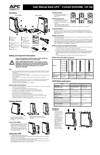
InventorySafety and General InformationInspect the package contents upon receipt. Notify the carrier and dealer if there is any damage.SAVE THESE INSTRUCTIONS - This manual contains important instructions that should be followed during installation and maintenance of the UPS and batteries. Failure to follow these instructions can result in equipment damage.UPS• This unit is designed for low power devices less than 50 Watts. When the UPS is on battery,the unit will shut down automatically to protect itself once the load on the UPS is greater than 50Watts.• This UPS is intended for indoor use only.• Do not operate this UPS in direct sunlight, in contact with fluids, or where there is excessivedust or humidity.• Be sure the air vents on the UPS are not blocked. Allow adequate space for properventilation.• The battery typically lasts for three to five years. Environmental factors impact battery life.Elevated ambient temperatures, poor quality AC power, and frequent short duration discharges will shorten battery life.• Connect the UPS power cable directly to a wall outlet.Mobile Power Pack (battery)• Do not short circuit this device. To avoid short circuit, keep the device away from any metalobjects (e.g., hair clips and keys).• It is normal that the battery will feel warm during heavy use.• Use this device as instructed to avoid electric shock; do not disassemble.• This unit is not user repairable; contact APC for tech support related issues.• Do not heat this device or throw it into a fire.• Do not drop or place the unit under a heavy object.• Keep this device away from high temperature, wet, or dusty environments.• During normal usage keep the device out in the open to allow excess heat to dissipate.• Charge M12USWH for 2.5 hours before initial use.• Keep the USB output port and micro-USB input port clean and free of obstruction.Getting StartedConnect the BatteryRemove all plastic films. With the USB ports positioned at the bottom, insert the mobile battery pack into the main unit.When the battery is inserted one LED will illuminate moving from the bottom to the top to confirm that the battery has been inserted properly.Using the UPSPress the POWER button located in frontof the UPS. The POWER button LED will illuminate and a single short beep will be audible to indicate that the UPS is turning on.The UPS provides surge protection and battery backup to low power equipment like modems, gateways, routers, cordless phone base units and V oIP base units.Note that high power devices like PCs or monitors may overload the UPS during a blackout. It is recommended that only low power devices be connected.Rotating OutletsBoth outlets can be rotated 90° and 45° to minimize adapter plug interference.USB charging portsThe three USB ports provide a total of 4.4A of DC power, and willprovide power even when the unit is on battery.Fast charging is available at the 2.4A USB port. This port integrates SmartCharging technology to maximize output according to the smartphone or tablet detected.Surge Only ModeThe battery can be removed and the UPS will continue to provide surge protection for the connected AC devices. When the battery is removed the POWER button LED will illuminate amber. In this mode the USB port will continue to provide charging power for smartphones and other USB devices.Mobile Power PackWhen removed from the UPS the battery can be used as a mobile power pack to charge devices in a mobile environment.To turn on the battery press the POWER button on the battery. The LEDs will illuminate to show battery capacity. After 20 seconds the unit will enter a power saving mode if it is not charging a device or being charged. If the unit is charging a device or being charged, after 20 seconds the LEDs will dim down to 10% brightness. Pressing the POWER button at any time will cause the LEDs to illuminate at 100% brightness for 20 seconds.Battery Charge and Capacity Information• Charge battery in the UPS for 2.5 hours prior to initial use. The battery will charge whetherthe UPS is on or off as long as there is AC power to the UPS.• Do not expect full battery runtime capability during the initial charge period.• To charge the battery using the micro-USB input, connect the battery to any USB chargingport. When separate from the UPS, battery charging is slower. When charging the battery using the USB port on a PC, the LEDs will flash more slowly to indicate slower rate of charge.• UPS runtime information is available on the APC Web site, .Mobile Power Pack Status IndicatorsUPS Status IndicatorsWall Mount Installation•Vertical installation, use 4 screws 15/16” (100 mm) in diame-ter. (Screws are not provided.)•Install the stabilizer feet using the 4 slots at the ends of each row of ventilation holes as seen in the figure below.•Orient the UPS to the desired location. Mount screws directly into stabi-lizer feet starting with the bottom pair.Capacity indicator LEDs UPS connector Mobile power pack (battery)Mobile Power Pack POWER buttonRotating outletsPower cordUSB cable Stabilizer feet (4 pcs)User Manual from the UPS and the battery.Plug the power cord into the back of the unit.Install the stabilizer feet using the 4 slots at the ends of each row of ventila-tion holesEventPOWER Button LED Audible Indicator On On Battery The LED flashes green.Not applicable Surge Only ModeThe LED illuminates amber.Not applicableLow Battery alarmThe UPS is supplying battery power and the battery is near a total discharge state.The LED illuminates green and flashes rapidly.The UPS emits 2 short beeps every 30 seconds.Replace BatteryThe battery is worn or needs to be replaced.The LED illuminates red only.None Overload ShutdownWhile on battery power an overloadcondition has occurred in one or more of the battery backup outlets while the UPS is operating on battery power.None Constant toneUSB Detected FaultAn error has occurred in the USB charger on the UPS.The LED alternatelyilluminates green / amber.None© 2015 APC by Schneider Electric. APC, the APC logo, and Back-UPS are owned by Schneider Electric Industries S.A.S., or their affiliated companies. All other trademarks are property of their respective owners.EN 990-966901/2015Voltage Sensitivity Adjustment (optional) The UPS detects and reacts to line voltage distortions by transferring to battery backup power to protect connected equipment. In situations where either the UPS or the connected equipment is too sensitive for the input voltage level it is necessary to adjust the transfer voltage.1.Connect the UPS to a wall outlet but make sure it is off.2.Press and hold the POWER button. After 10 seconds the POWER button LED will illuminatealternately green-red to indicate that the UPS is in Program mode.3.After releasing the POWER button the POWER button LED will illuminate either green,amber, or red to indicate the current sensitivity level. Press the POWER button to changesensitivity. Refer to the table below for an explanation of the sensitivity setting and transfervoltage sensitivity level that corresponds to each LED color.4.To exit Program mode wait five seconds and all LED indicators will extinguish. Programmode is no longer active.Mute Low Battery AlarmFollow the instructions below to adjust the audio setting of the UPS to enable or disable low battery alarm. To change the setting make sure the UPS is on.Make sure the unit is on. Press and hold the POWER button. Releasing the POWER button after hearing the 3rd short beep will toggle the low battery alarm mute function. The UPS will emit a short double beep to confirm that the low battery alarm has been disabled. If the UPS emits a 1- second beep it indicates that the low battery alarm is audible.Note: The default setting of the low battery alarm is audible.UPS SpecificationsMobile Power Pack (battery) SpecificationsReplace BatteryDeliver the used battery to a recycling facility.Replace the used battery with an APC by Schneider Electric approved battery.Replacement batteries can be ordered through the APC by Schneider Electric Website, . Battery replacement part for UPS BGE50ML is M12USWH. WarrantySchneider Electric IT (SEIT) warrants its products to be free from defects in materials andworkmanship for a period of three (3) years from the date of purchase. SE IT obligation under this warranty is limited to repairing or replacing, at its sole discretion, any such defective products. This warranty does not apply to battery wear from use, equipment that has been damaged by accident, negligence or misapplication or has been altered or modified in any way. SEIT standard procedure is to replace the original unit with a factory reconditioned unit. Customers who must have the original unit back due to the assignment of asset tags and set depreciation schedules must declare such a need at first contact with an SEIT Technical Support representative. SEIT will ship the replacement unit once the defective unit has been received by the repair department, or cross ship upon the receipt of a valid credit card number. The customer pays for shipping the unit to SEIT.SEIT pays ground freight transportation costs to ship the replacement unit to the customer. For full warranty information refer to .TroubleshootingServiceIf the unit requires service, do not return it to the dealer. Follow these steps:1.Review the Troubleshooting section of the manual to eliminate common problems.2.If the problem persists, contact Schneider Electric IT (SEIT) Customer Support through theAPC by Schneider Electric Web site, .a.Note the model number and serial number and the date of purchase.b.Call SEIT Customer Support and a technician will attempt to solve the problem over thephone. If this is not possible, the technician will issue a Returned Material AuthorizationNumber (RMA#).c.If the unit is under warranty, the repairs are free.d.Service procedures and returns may vary internationally. Refer to the APC by SchneiderElectric Web site for country specific instructions.3.Pack the unit in the original packaging whenever possible to avoid damage in transit. Neveruse foam beads for packaging. Damage sustained in transit is not covered under warranty.4.Always DISCONNECT THE UPS BATTERIES before shipping. The United StatesDepartment of Transportation (DOT), and the International Air Transport Association(IATA) regulations require that UPS batteries be disconnected before shipping. Theinternal batteries may remain in the UPS.5.Write the RMA# provided by Customer Support on the outside of the package.6.Return the unit by insured, pre-paid carrier to the address provided by Customer Support APC by Schneider Electric IT Customer Support WorldwideFor country specific customer support, go to the APC by Schneider Electric Web site,.EMC ComplianceThis device complies with part 15 of the FCC rules. Operation is subject to the following two conditions: (1) This device may not cause harmful interference, and (2) This device must accept any interference received, including interference that may cause undesired operation.This UPS is certified to comply with California Battery Charger System regulations. Formore information go to/site/recycle/index.cfm/energy-efficiency/cec-battery-charger/LED Flashes SensitivitySettingInput Voltage Range(AC Operation)Recommended UseGreen LOW88 Vac to 142 Vac Use this setting with equipment that is less sensitive to fluctuations in voltage or waveform distortions.Red MEDIUM92 Vac to 139 Vac Factory default setting. Use this setting undernormal conditions.Amber HIGH96 Vac to 136 Vac Use this setting when connected equipment issensitive to voltage and waveform fluctuations.AC Input V oltage120 Vac NominalFrequency50/60 Hz + 3Hz auto-sensingBrownout Transfer92 Vac TypicalOver-voltage Transfer139 Vac TypicalProtection Resettable circuit breakerSurge Protection Computer gradeAC Output UPS Capacity 84 V A, 50 WTotal Amperage (AC outlets)0.7 AV oltage - On Battery115 Vac ± 8%Frequency - On Battery50/60 Hz + 1Transfer Time 6 ms Typical, 10 ms maximumUSB Output Output Current 1.0AOutput V oltage5VCharger Compatibility USB Battery Charging Specification 1.2Physical Net Weight 1.7 lb (0.8 kg)DimensionsLength x Width x Height 7.7 in x 7.0 in x 2.1 in (19.6 cm x 17.8 cm x 5.4 cm)Operating Temperature32º F to 104º F (0º C to 40º C) Storage Temperature5º F to 113º F (–15º C to 45º C) Operating Relative Humidity0 to 95% non-condensing humidity Operating Elevation0 to 10,000 ft (0 to 3000 m)Cord Lengths Power Cord59.0 in (150.0 cm) USB Cord11.0 in (27.9 cm)Type Lithium-ion batteryCapacity11400mAhRating41.2 WhInput current (Maximum)micro-USB: 2.1ARated input voltage5V dcOutput current USB1: 2.4A, USB2: 1.0AOutput voltage5VCapacity indicator light 5 level LEDsCapacity indicator brightness levels50% in the UPS. As mobile power pack 100% afterpressing the POWER button. 10% after 20 secondswhen charging a device or being charged. Charging time 2.5 hours (UPS), 8 hours (micro-USB) Dimensions (L x W x H) 5.1 x 2.9 x 0.9 in (13.0 x 7.4 x 2.2 cm)Weight0.6 lb (267g)Operating temperature32°F- 104°F (0°C- 40°C)Smart Charging (2.4A port only)Maximum output depends on the client device.Problem and Possible Cause SolutionThe UPS will not turn onThe UPS has not been turned on.Press the POWER button.The UPS is not connected to AC power,there is no AC power available at the walloutlet, or the AC power is experiencing abrownout or over voltage condition.Make sure the battery has been inserted into the UPSwhen attempting to turn on the UPS without AC power.In the event that the UPS receives no AC power and thebattery is connected, a cold-start can be initiated. Pressand hold the POWER button until the UPS emits twobeeps.The UPS is on, the POWER button illuminated redThe battery is worn or needs repair..Contact Schneider Electric IT (SEIT) Technical Supportfor more in depth troubleshooting..Connected equipment loses powerA UPS overload condition has occurred.Remove all nonessential equipment connected to theoutlets. Reconnect equipment to the UPS, one device at atime.The battery is completely discharged.Connect the UPS to AC power to allow the battery torecharge.The UPS may require service.Contact Schneider Electric IT (SEIT) Technical Supportfor more in depth troubleshooting.The UPS has an inadequate battery runtimeThe battery is not fully charged.The battery is near the end of useful lifeand should be replaced.Leave the UPS connected to AC power for 2.5 hourswhile the battery charges to full capacity.As a battery ages, the runtime capability decreases.Contact APC by Schneider Electric at the Web site, to order replacement batteries.USB charging is slowCharging a device using the UPS's USBcharger is slower than the device's originalUSB chargerThe amount of power a device draws depends on itscompatibility with the USB Battery ChargingSpecification 1.2. Compatible devices can draw morepower than devices that are less compatible. For devicesthat can charge using input greater than 1A make sure thatthe device is connected to the 2.4A USB charging port. USB charging stops and the POWER button LED alternately illuminates green / amberThe USB port on the UPS is overloaded orhas encountered an error.Disconnect device from the USB port on the UPS. USBcharging will resume when the LED turns green. ContactSEIT Technical Support if the LED continues to alternategreen / amber.USB charging stops and the battery pack capacity indicators LEDs all flash simultaneously One or two USB ports on the mobile powerpack is overloaded or has encountered anerror.Disconnect device(s) from the USB port(s) on the mobilepower pack. When the mobile power pack is not pairedwith the UPS the power pack will enter safe mode if theUSB error has not been resolved within 30 seconds. Battery charging is slowThe charging time of battery variesdepending on the charging connection.Charge the battery inside the UPS for best results. Usingthe micro-USB port to charge the battery will requiremore time. The speed is also dependent on the type ofUSB charger. Some USB chargers support 1A and othersup to 2.4A. More powerful chargers will reduce the timerequired. USB ports on a PC can also charge the batterybut older PCs only support 500mA which will result ineven more time to charge.。
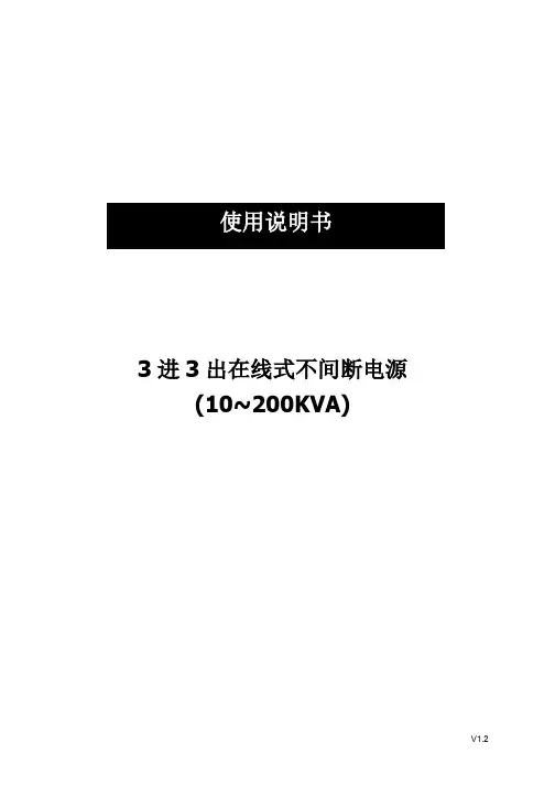
3进3出在线式不间断电源(10~200KVA)V1.2目录1. 产品介绍 (1)1.1 简介 (1)1.2 基本组成 (1)1.3 工作模式 (1)1.4 产品概览 (5)2. 注意事项 (6)2.1 常用标志说明 (6)2.2 安全事项说明 (7)3. 机柜安装 (9)3.1 安装环境要求 (9)3.2 卸货开箱 (10)4. 电气安装 (12)4.1 电源端口 (12)4.2 通讯端口 (16)5. 调试 (19)5.1 开机步骤 (19)5.2 关机步骤 (19)5.3 维修旁路使用步骤 (20)6. 人机界面 (21)6.1 控制面板 (21)6.2 液晶屏显示说明 (22)6.3 功能菜单操作说明 (24)7. 使用维护指南 (41)7.1 系统维护 (41)7.2 电池维护 (41)8. 故障诊断及处理 (42)8.1 警告代码说明 (42)8.2 故障代码说明 (43)9. 单机电气规格 (45)10. 并机安装指导 (48)10.1 概述 (48)10.2 并机安装 (48)10.3 并机设置及LCD显示 (53)10.4 并机规格 (53)10.5 并机故障诊断及处理 (54)1.产品介绍1.1简介本系列UPS是一款纯正弦波输出的双变换在线式不间断电源系统,为重要负载提供不受电网干扰、稳压、稳频的电力供应的电源设备。
当市电掉电后,UPS将电池能量逆变输出到负载,实现不间断输出。
本系列UPS采用输出隔离变压器的高频双变换结构和先进的全数字控制技术,实现稳定、干净、不间断电源输出。
同时还提供多样化的通讯方案,及友好的人机界面,方便用户对机器进行设置及监控。
通讯部分提供MODBUS,RS232以及可扩展的智能插槽。
1.2基本组成本系列UPS系统主要由整流模块和逆变模块组成交流到直流再到交流的双变换电路、静态旁路、维修旁路、电池充放电回路等几个主要的模块组成。
市电与旁路通过反向并联的可控硅作为切换开关来进行切换。

目录第1章安全说明 (1)1.1 符号说明 (1)1.2 安全注意事项 (1)第2章产品介绍 (3)2.1 产品概述 (3)2.2 型号规则 (3)2.3 UPS 外观 (4)2.4 工作原理 (6)第3章安装 (7)3.1 开箱检查 (7)3.2 安装注意事项 (7)3.3 接线方法 (7)3.3.1 输入接线 (8)3.3.2 输出接线 (8)3.3.3 长效机外接电池 (9)3.3.4 通信接线 (10)3.3.5 通讯浪涌保护接口 (10)第4章运行和操作 (11)4.1 操作面板 (11)4.2 UPS 主要运行模式 (13)4.2.1 市电模式 (13)4.2.2 电池模式 (13)4.2.3 旁路模式 (13)4.3 操作 (14)4.3.1 开机操作 (14)4.3.2 关机操作 (14)4.3.3 电池自检操作 (14)4.3.4 消音操作 (15)4.3.5 LED面板显示和告警音说明 (15)4.3.6 LCD面板显示, 告警音和LCD显示内容说明 (16)第5章维护和保养 (19)5.1 常规维护 (19)5.2 电池维护 (19)第6章故障处理 (20)6.1 LED 操作面板故障处理表 (20)6.2 LCD操作面板故障处理表 (21)第7章产品规格.......................................................................................................................................... 7-17.1 基本电气规格 ................................................................................................................................. 7-17.2 尺寸重量 ......................................................................................................................................... 7-27.3 应用环境 ......................................................................................................................................... 7-27.4 传导辐射 ......................................................................................................................................... 7-27.5 安规 ................................................................................................................................................. 7-27.6 工业标准 ......................................................................................................................................... 7-2 维修保证.......................................................................................................................... 错误!未定义书签。