CGWP安装操作手册
- 格式:pdf
- 大小:981.28 KB
- 文档页数:28

CWP软件的安装与简单使用手册CWP软件的安装一.在LINUX下建立用户CWP,在CWP下建立目录path,将源文件cwp.su.all.37.tar.Z放二.到path目录下,并建立bin文件夹三.在CWP用户主目录下显示隐藏文件,修改.bash_profile 文件,在已有的export之后另起一行,分别添加export CWPROOT=/home/CWP/path,再于PA TH=$PA TH:$HOME/bin后添加:/home/CWP/path/bin:/home/CWP退出保存四.从终端中分别输入cd pathzcat cwp.su.all.37.tar.Z | tar –xvf-…待终端中反映完毕,分别输入cd srcmake installmake xtinstallmake mglinstallmake utilsmake xminstallmake sfinstall这期间可能有系统安装所等待的时间,不用急,但凡遇到yes/no,一路y下来即可。
四.为了检查是否安装完毕,在终端中输入Suplane > data.suSuxwigb < data.su &若出现一个简单的图像,则成功!CWP软件的简单说明一、文中涉及的命令全部以小写形式,均可在终端窗口下输入,以次获取自述帮助。
先说几个命令:suplane和suxwigb,more。
suplane作用是产生一个简单的零偏移距su文件,suxwigb是一个典型的X—windows 绘制图形工具,如例子:suplane > data.susuxwigb < data.sumore < data.su比较全面的了解它们,请在终端中输入suplane , suxwigb ,more 。
二、关于DEMOS的应用所有DEMOS必须把文件拷到用户根目录下,而后依照readme文件中的执行顺序,在终端中输入文件名。


FOR TERMINATION OF CABLES WITH SINGLE WIRE ARMOUR (SWA) FOR INDOOR USETECHNICAL DATAINSTALLATION INSTRUCTIONSInstallation should only be performed by a competent person using the correct tools. Read all instructions before beginning installation.ACCESSORIESThe following accessories are available from CMP Products, as optional extras, to assist with fixing, sealing and earthing :-Locknut | Earth Tag | Serrated Washer | Shroud *CABLE GLANDTYPE BWINSTALLATION INSTRUCTIONS FOR CMP CABLE GLAND TYPE BWGlasshouse Street • St. Peters • Newcastle upon Tyne • NE6 1BSTel: +44 191 265 7411 • Fax: +44 1670 715 646E-Mail:********************************.uk•Web:CABLE GLAND TYPE : BWDESIGN STANDARDS : BS6121:1989PROCESS CONTROL SYSTEM : BS EN ISO 9001C M PD o c u m e n t N o . F I 450 I s s u e 4NOTE: *CMP SOLO LSF Halogen Free Shrouds also available for the full range on request. + Alternative armour clamping range available for non-standard armour sizes.Marine Approvals including Lloyds & ABS are also available from CMP Products.SCAN FOR INSTALLATION VIDEOSDate Printed: INSTALLATION INSTRUCTIONS FOR CMP CABLE GLAND TYPES BWCABLE GLAND COMPONENTS - It is not necessary to dismantle the cable gland any further than illustrated below 1. Entry Component 2. NUTPLEASE READ ALL INSTRUCTIONS CAREFULLY BEFORE BEGINNING THE INSTALLATION1. 1. Separate components (1), and (2). If required, fit a shroud over the cable outer sheath. Prepare the cable by removing the cable outer sheath and the braid/armour to suit the geometry of the equipment.Remove a further 18mm (max) of outer sheath to expose the armour. If applicable remove any tapes or wrappings to expose the inner sheath.NOTE: On maximum size cables the clamping ring may only pass over the armour.3. Pass the cable through the entry item and evenly space the braid/armour around the cone.4. While continuing to push the cable forward to maintain contact between the armour and the cone, tighten the Nut (2) by hand to engage the armour.Hold the Entry Component (1) with a spanner and tighten the Nut (2) using a spanner until the armour is secured.5. The installation is now complete.。

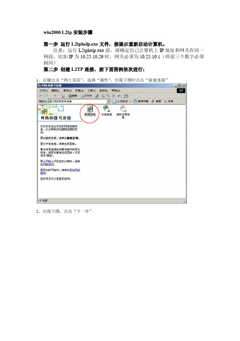
win2000 L2tp安装步骤第一步运行L2tphelp.exe文件,按提示重新启动计算机。
注意:运行L2tphelp.exe前,请确定自己计算机上IP地址和网关在同一网段,比如IP为10.25.10.29时,网关必须为10.25.10.1(即前三个数字必须相同)第二步创建L2TP连接,按下面图例依次进行:1、右键点击“网上邻居”,选择“属性”,出现下图时点击“新建连接”2、出现下图,点击“下一步”3、出现下图,选择“通过Internet连接到专用网络”,并点击“下一步”4、出现下图时选择“不拨初始连接”,点击“下一步”5、出现下图时,输入10.5.1.9或,点击“下一步”6、出现下图时可随意选择,点击“下一步”7、出现下图时,可随意输入连接名(如本例为“虚拟专用连接2”),也可选择“在我的桌面上添加一快捷方式”,点击“完成”8、在下图中输入从校网中心申请的认证用户名和密码,并点击“属性”按钮:注意:本例仅为示范,实际域后缀为a、c、d几类,分别解释如下:***@a 国内用户,***代表已经拥有的帐号名;***@c 教工国际包月用户,***代表已经拥有的帐号名;***@d 学生国际包月用户,***代表已经拥有的帐号名。
9、出现下图时点击“安全措施”选项,去掉“要求数据加密”前的勾同时点击“网络”选项,选择VPN类型为“第2层隧道协议L2TP”至此,已完成配置,点击“确定”完成建立连接。
第三步首次拨号前更改一遍帐号密码。
注意:帐号指第8步中所示的***部分。
更改密码过程如下:1、打开Internet Explorer浏览器,地址栏中输入2、以自己的帐号名和密码登录3、登录后按下图鼠标所示点击“个人设置”4、如下图所示点击“修改密码”5、出现下图后按提示修改密码,按“确定”按钮后关闭窗口。
修改密码完成第四步进行拨号:回到“网络和拨号连接”窗口,双击新建的拨号连接(如本例中的“虚拟专用连接2”),输入用户名(如***@a或***@c等一类形式)和密码,按“连接”进行拨号。

P/N: 1802001043316 *1802001043316*CA Series for PC/104 and CB Series for PC/104-Plus Quick Installation GuideVersion 1.2, December 2019Technical Support Contact Information/supportMoxa Americas:Toll-free: 1-888-669-2872 Tel: 1-714-528-6777 Fax: 1-714-528-6778 Moxa China (Shanghai office): Toll-free: 800-820-5036 Tel: +86-21-5258-9955 Fax: +86-21-5258-5505 Moxa Europe:Tel: +49-89-3 70 03 99-0 Fax: +49-89-3 70 03 99-99 Moxa Asia-Pacific:Tel: +886-2-8919-1230 Fax: +886-2-8919-1231 Moxa India:Tel: +91-80-4172-9088 Fax: +91-80-4132-10452019 Moxa Inc. All rights reserved.OverviewMoxa offers a wide selection of PC/104 and PC/104-Plus serial boards that provide industrial-grade connections to multiple serial devices. The CA Serial Board Series is for PC/104 modules while the CB Serial Board series is for PC/104-Plus module.Package ChecklistPC/104 or PC/104-Plus boards are shipped with the following items: •Moxa multiport serial board (PC/104 module is for CA Series;PC/104-Plus module is for CB Series)•Quick installation guide (printed)•Warranty cardPlease notify your sales representative if any of the above items are missing or damaged.Hardware InstallationThe PC/104 or PC/104-Plus MUST be plugged into the PC before the driver is installed. Follow these steps below.CA Series CB SeriesStep 1: Turn the embeddedcomputer off Step 1: Turn the embeddedcomputer offStep 2: Set the I/O address,Interrupt vector, IRQ, andserial interface(Refer to the section:"Block Diagram, I/OAddress, Interrupt Vector,Serial Interface") Step 2: Set interface(Refer to section: "BlockDiagram, I/O Address,Interrupt Vector, SerialInterface")Step 3: Insert the module into the PC/104 slot Step 3: Insert the module intoPC/104 slot.Step 4: Screw the control board in place Step 4: Screw the control board in place.Step 5: Connect the cables(Refer to the section: "PinAssignments") Step 5: Connect the cables.(Refer to the section: "PinAssignments")Step 6: Turn the embeddedcomputer on Step 6: Turn the embeddedcomputer on.Software InstallationFollow these steps:Step 1: Get the driver at .Based on the OS type, choose the corresponding driver.Step 2: Install Driver•For Windows (Take the installation of Win7 as an example)2.1. Unzip and execute the .exe file2.2. Follow the instructions to install the driversNote: If your model is from the CB Series, then theinstallation is done. Otherwise, please do the followingsteps for the CA Series models.2.3. Follow the instructions of “Add Hardware Wizard”2.4. Follow the instruction of “Found Hardware Wizard”.This step is for mapping your driver and hardwaredevice.2.5. Repeat steps 2.3 and 2.4 to activate the otherserial ports.•For Linux2.1. Get the driver at and unzip thefile:#cd /#mkdir moxa#cd moxa#cp /<driverdirectory>/driv_linux_smart_<version>_build_<build_date>.tgz#tar-zxvfdriv_linux_smart_<version>_build_<build_date>.tgz2.2. Install the driver:#cd mxser#./mxinstall2.3. Install the module driver, using the hardwaresettings that you have selected(This step is only for the CA Series)For example: I/O address of 0x180, an INT vector of0x1C0, and an IRQ of 10#cd mxser#make clean#make install#cd /moxa/mxser/driver#./msmknod#modprobe mxser ioaddr=0x180 iovect=0x1C0irq=102.4. You can use the Moxa diagnostic utility to verifythe driver’s status:#cd /moxa/mxser/utility/diag#./msdiag2.5 You can use the Moxa terminal utility to test theTTY ports:#cd /moxa/mxser/utility/term#./mstermBlock Diagram, I/O Address, Interrupt Vector, Serial InterfaceBlock Diagrams CA SeriesCA-108CA-104 V2CA-114CA-134I,CA-132 V2,CA-132I V2CB SeriesCB-108CB-114CB-134II/O Address (Only for the CA Series)Use DIP switch SW1 to set port 1’s I/O base address. The other ports will be configured automatically.The default I/O base address is 0×180 and allows settings from 0×000 to 0×3FF.Some popular settings are provided below:For example, an I/O base address of 0×180should be set as follows:A3 A4 A5 A6 A7 A8 A9 HexON ON ON ON OFF OFF ON 0x180The other serial ports will be set automaticallyto 0×188, 0×190, 0×198, etc.Interrupt Vector (Only for CA Series)A3 A4 A5 A6 A7 A8 A98 1 2 4 8 1 2 HexON ON ON ON ON ON ON0×000ON ON ON ON ON ON off 0×200 ON ON ON ON ON off off 0×300 ON ON ON ON off off off 0×380 ON ON ON off off off off 0×3C0 ON ON off off off off off 0×3E0 ON off off off off off off 0×3F0 off off off off off off off 0×3F8 off ON ON ON ON ON ON 0×008 off off ON ON ON ON ON 0×018 off off off ON ON ON ON 0×038 off off off off ON ON ON 0×078 off off off off off ON ON 0×0F8 off off off off off ON off 0×2F8 Use DIP switch SW2 to set port 1’s interrupt vector.The default interrupt vector is 0×1C0, with SW2 set as follows: A3 A4 A5 A6 A7 A8 A9 Hex ON ON ON ON OFF OFF ON 0x1C0Serial InterfaceCA SeriesCA-114Interface RS-232 RS-422 RS-485 (4w) RS-485 (2w) SW1 - - ON OFFSW2 - ON OFF OFFSW3 ON OFF OFF OFFCA-134I, CA-132 V2, and CA-132I V2Interface 2-wire/4-wire RS-422/RS-485RS-422 - OFF 4-wire RS-485 OFF ON2-wire RS-485 ON ONCB SeriesCB-114Interface RS-232 RS-422 RS-485 (4w) RS-485 (2w) SW1 - - ON OFFSW2 - ON OFF OFFSW3 ON OFF OFF OFFCB-134IInterface 2-wire/4-wire RS-422/RS-485RS-422 - OFF 4-wire RS-485 OFF ON2-wire RS-485 ON ONPin AssignmentsRS-232(CA-108/CB-108, CA-114/CB-114, and CA-104)NOTE Note that there are two 40-pin box header connectors on the CA-108/CB-108, of which each connects to 4 serial ports.Pin Signal Pin Signal Pin Signal Pin Signal1 DCD0 11 DCD1 21 DCD2 31 DCD32 DSR0 12 DSR1 22 DSR2 32 DSR33 RxD0 13 RxD1 23 RxD2 33 RxD34 RTS0 14 RTS1 24 RTS2 34 RTS35 TxD0 15 TxD1 25 TxD2 35 TxD36 CTS0 16 CTS1 26 CTS2 36 CTS37 DTR0 17 DTR1 27 DTR2 37 DTR38 – 18 – 28 – 38 –9 GND0 19 GND1 29 GND2 39 GND3 RS-422, 4-wire RS-485(CA-132, CA-132I, CA-114/CB-114, and CA-134I)With regard to the CA Series, pins 21 to 40 apply to CA-114 and CA-134I only.Pin Signal Pin Signal Pin* Signal* Pin* Signal* 1 TxD0-(A) 11 TxD1-(A) 21 TxD2-(A) 31 TxD3-(A) 3 TxD0+(B) 13 TxD1+(B) 23 TxD2+(B) 33 TxD3+(B) 5 RxD0+(B) 15 RxD1+(B) 25 RxD2+(B) 35 RxD3+(B) 7 RxD0-(A) 17 RxD1-(A) 27 RxD2-(A) 37 RxD3-(A) 9 GND0 19 GND1 29 GND2 39 GND32-wire RS-485(CA-132, CA-132I, CA-114/CB-114, and CA-134I)With regard to the CA Series, pins 21 to 40 apply to the CA-114 and CA-134I only.Pin Signal Pin Signal Pin* Signal* Pin* Signal*5 Data0+(B) 15 Data1+(B) 25 Data2+(B) 35 Data3+(B)7 Data0-(A) 17 Data1-(A) 27 Data2-(A) 37 Data3-(A)9 GND0 19 GND1 29 GND2 39 GND3。
V1.0版权所有©2020北京潍鲸科技有限公司。
保留所有权利。
本文档的版权归北京潍鲸科技有限公司所有,未经许可和授权,任何组织或个人不得擅自摘抄、复制本文档的部分或全部内容,并不得以任何形式传播。
免责声明:本文档仅作为使用指导,针对当前版本生效。
由于产品升级或其他原因,文档内容会不定期更新,恕不另行通知。
您购买或试用的产品、服务及特性应受北京潍鲸公司商业合同和条款的约束,文档中描述的部分产品、服务及特性可能不在您购买或使用的范围之内。
目录1前言42WordPress介绍 (5)3WordPress安装说明 (6)3.1支持环境 (6)3.2服务内容 (6)3.3注意事项 (6)4联系我们 (7)Web运行环境故障排查说明书1前言北京潍鲸科技有限公司是一家业务完全基于云计算的服务型公司,是一家面向企业级IT/云服务公司,坚持以客户为中心,聚焦资源整合。
潍鲸集成云厂商的工具资源、服务交付资源,推出针对各云厂商产品的服务解决方案,秉承开放、合作、共赢的原则,做好云生态的积极建设者,为企业用户提供全方位多选择的云服务模式。
潍鲸科技专注互联网业务,提供一站式运维服务解决方案,专为客户提供上云的咨询、设计、迁移、运维以及运营的云服务,其中包括上云的咨询设计、数据迁移、运维托管、大数据、混合云管理、安全以及集成服务等。
为企业搭建云计算时代的IT基础技术框架及运维服务。
概述本手册主要介绍潍鲸科技关于WordPress安装配置说明书。
注:本文下述北京潍鲸科技有限公司简称“潍鲸科技”使用对象安装实施人员、开发工程师、运维工程师。
修订记录修订记录累积了每次文档更新的说明。
最新版本的文档包含以前所有文档版本的更新内容。
文档版本变更记录V1.0.0第一次发布。
2W ORD P RESS介绍WordPress是使用PHP语言开发的博客平台,用户可以在支持PHP和MySQL 数据库的服务器上架设属于自己的网站。
也可以把WordPress当作一个内容管理系统(CMS)来使用。
安装运行环境
1.去 下载wamp,如下图,注意这里要安装wamp,而不能安装xampp,原因不明。
2.安装wamp。
3.点击右下角的那个wamp图标,会出现如下界面,选“start all services”,运行apache和mysql。
4.测试wamp是否正常运行,点击上图中phpMyAdmin,会出现以下界面证明安装成功。
4.创建wordpres所需要的数据库。
在上图中,输入wordpressDB(数据库名称),如下图,再点击创建按钮即可。
安装wordPress
1.下载wordpress,/。
2.下载后解压,运行里面的readme.html ,根据教程完成以下的安装步骤。
修改以下三项就可以了,然后保存。
3.重命名刚才的wp-config-sample.php 为wp-config.php。
4.把整个wordpress文件夹拷贝到C盘的wamp\www目录中。
5.在浏览器中输入http://localhost/wordpress/wp-admin/install.php,出现下图,输入相关信息后,点击安装按钮。
6.成功后出现下图,使用它给出的用户名和密码,点击登录。
6.成功如下:。
Centum VP R4.03操作站安装手册1、a.安装之前首先关闭防火墙:开始菜单——所以程序——控制面板——安全中心——关闭防火墙。
b.关闭屏幕保护:桌面右键属性——屏幕保护程序,选择无;再击电源,关闭监示器、关闭硬盘以及系统待机全部选择从不。
2、桌面→右键我的电脑→计算机名→更改(工程师站为HIS0164,其他依次往下排),请注意这里为大写。
关闭电脑(插拔网卡请拔掉电脑电源线,网卡插到PCI 75W的插槽,手尽量不要接触网卡电子元器件,防止静电)拿出两个VI702卡,需要进行网卡拨号,在网卡的左上角,会看到如下图所示两个拨号的地方,其中DOMAIN代表域号的意思,STATION代表站号的意思,如下面图数字1-8代表位号,横河最低位是第8位,最高位是第2位,所以上面从8到2写的是LSB和MSB,8代表2的0次方为1,7代表2的1次方为2,6代表2的2次方为4,以此类推,2代表2的6次方,也就是最大的64,我们工程师站就是64号站。
在图的左边,有个上下的数字1和0,在默认的情况下,域号和站号的小开关都是在下面,也就是在0的位置,然后在DOMAIN的地方,将2块卡的第8位都拨到1的位置,也就是说我们是在1号域(2的0次方),然后在STATION的地方,将第1块VI701卡的第7位、第6位、第5位、第4位和第3位拨到1的位置,(2+4+8+16+32=62,也就是HIS0162),再将第2块卡的第8位、第6位、第5位、第4位和第3位拨到1的位置,(1+4+8+16+32=61,也就是HIS0161),最后要说的是第1位的意思:他是个奇偶校验位,只有当下面拨号的数量为偶数的情况下,才将这一位拨到1,而刚刚拨HIS0161和HIS1062的时候,会发现,2个都只拨了5个开关,所以是不用管第1位的。
将这2个VI702卡插入对应电脑的PCI插槽上,也就是大家知道安装独立显卡的那个地方。
将实现铺设好的网线,按照BUS1、BUS2对应查好。