YCAG-安装操作维护手册
- 格式:pdf
- 大小:14.92 MB
- 文档页数:32

汽车配件管理软件操作手册汽车配件管理软件操作手册江苏省电信有限公司索引1 登陆平台 .。
..。
...。
.。
.。
.。
.。
..。
.。
..。
....。
..。
..。
..。
.。
.......。
.。
.。
..。
.。
.。
..。
.。
.。
.。
.。
..。
..。
.。
.。
.。
.。
.。
.。
..。
.。
.。
.。
5 2 ASUPERCRM包含的业务范围。
..。
.。
.。
.。
....。
...。
...。
.。
.。
.。
.。
.。
.。
.....。
.。
....。
.。
.。
.....。
7 3 主页面 ......。
.。
..。
..。
..。
.。
..。
..。
..。
.。
..。
.。
.。
..。
.。
.。
..。
..。
.。
.。
.。
.。
.。
.。
.。
.。
.。
..。
.。
.....。
.。
.。
.。
.。
...。
.。
.。
.。
9 3。
1 业务流程图。
.。
.。
..。
..。
.。
.。
.。
.。
.。
..。
...。
.。
.。
.。
...。
.。
.。
.。
.。
.。
.。
.。
...。
.。
.。
.。
..。
....。
.. 9 3.2 快捷新建功能。
..。
.。
.。
.。
..。
...。
..。
.。
.。
.。
.。
..。
..。
.。
.。
..。
.。
.。
.。
..。
.。
..。
.。
...。
.。
....。
9 3。
3 全局搜索功能。
..。
.。
.。
..。
.。
.。
.。
.。
..。
.。
.....。
.。
.。
....。
..。
.。
..。
.。
.。
..。
.。
....。
...。
.。
..。
.。
...。
.。
.。
. 9 3。
4 配置主页 .。
.。
.。
.。
.。
...。
..。
...。
.。
.。
.。
..。
.。
.。
.。
....。
.。
...。
..。
.。
.。
..。
.。
..。
.。
..。
..。
.。
..。
.。
.。
..。
9 4 基本操作 .。
..。
.。
.。
..。
.。
.。
...。
.。
..。
.。
..。
.。
..。
.。
.。
..。
....。
...。
...。
.。
..。
.。
.。
....。
..。
....。
.。
.....。
..。
.。
....。
.。
.。
.。
. 11 4。
1 系统工具菜单 .。
.。
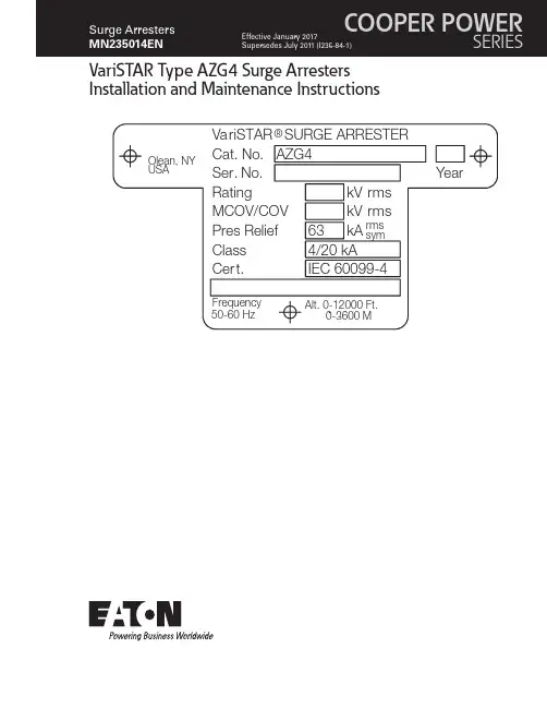
..。
VariSTAR Type AZG4 Surge Arresters Installation and Maintenance InstructionsDISCLAIMER OF WARRANTIES AND LIMITATION OF LIABILITYThe information, recommendations, descriptions and safety notations in this document are based on Eaton Corporation’s (“Eaton”) experience and judgment and may not cover all contingencies. If further information is required, an Eaton sales office should be consulted. Sale of the product shown in this literature is subject to the terms and conditions outlined in appropriate Eaton selling policies or other contractual agreement between Eaton and the purchaser.THERE ARE NO UNDERSTANDINGS, AGREEMENTS, WARRANTIES, EXPRESSED OR IMPLIED, INCLUDING WARRANTIES OF FITNESS FOR A PARTICULAR PURPOSE OR MERCHANTABILITY, OTHER THAN THOSE SPECIFICALL Y SET OUT IN ANY EXISTING CONTRACT BETWEEN THE PARTIES. ANY SUCH CONTRACT STATES THE ENTIRE OBLIGATION OF EATON. THE CONTENTS OF THIS DOCUMENT SHALL NOT BECOME PART OF OR MODIFY ANY CONTRACT BETWEEN THE PARTIES. In no event will Eaton be responsible to the purchaser or user in contract, in tort (including negligence), strict liability or other-wise for any special, indirect, incidental or consequential damage or loss whatsoever, including but not limited to damage or loss of use of equipment, plant or power system, cost of capital, loss of power, additional expenses in the use of existing power facilities, or claims against the purchaser or user by its customers resulting from the use of the information, recommendations and descriptions contained herein. The information contained in this manual is subject to changewithout notice.iINSTALLATION AND MAINTENANCE INSTRUCTIONS MN235014EN January 2017ContentsDISCLAIMER OF WARRANTIES AND LIMITATION OF LIABILITY . . . . . . . . . . . . . . . . . . . . . . . . . . . . . . . . . . . .I SAFETY INFORMATION . . . . . . . . . . . . . . . . . . . . . . . . . . . . . . . . . . . . . . . . . . . . . . . . . . . . . . . . . . . . . . . . . . . .III Safety instructions (iii)PRODUCT INFORMATION . . . . . . . . . . . . . . . . . . . . . . . . . . . . . . . . . . . . . . . . . . . . . . . . . . . . . . . . . . . . . . . . . . .1 Introduction (1)GENERAL APPLICATION RECOMMENDATIONS . . . . . . . . . . . . . . . . . . . . . . . . . . . . . . . . . . . . . . . . . . . . . . . . .1 IDENTIFICATION . . . . . . . . . . . . . . . . . . . . . . . . . . . . . . . . . . . . . . . . . . . . . . . . . . . . . . . . . . . . . . . . . . . . . . . . . .1 ASSEMBL Y . . . . . . . . . . . . . . . . . . . . . . . . . . . . . . . . . . . . . . . . . . . . . . . . . . . . . . . . . . . . . . . . . . . . . . . . . . . . . . .1 Base or Foundation Mounting (2)Bracket or Structure Mounting (2)Suspension Mounting (2)ELECTRICAL CONNECTIONS . . . . . . . . . . . . . . . . . . . . . . . . . . . . . . . . . . . . . . . . . . . . . . . . . . . . . . . . . . . . . . . .2 MAINTENANCE . . . . . . . . . . . . . . . . . . . . . . . . . . . . . . . . . . . . . . . . . . . . . . . . . . . . . . . . . . . . . . . . . . . . . . . . . . . . . . . . . . . . . . .3ii INSTALLATION AND MAINTENANCE INSTRUCTIONS MN235014EN January 2017iiiINSTALLATION AND MAINTENANCE INSTRUCTIONS MN235014EN January 2017Eaton’s Cooper Power series products meet or exceed all applicable industry standards relating to product safety. We actively promote safe practices in the use and maintenance of our products through our service literature, instructional training programs, and the continuous efforts of all Eaton employees involved in product design, manufacture, marketing and service.We strongly urge that you always follow all locally approved safety procedures and safety instructions when working around high-voltage lines and equipment and support our “Safety For Life” mission.1VariSTAR Type AZG4 Surge Arresters Installation and Maintenance InstructionsINSTALLATION AND MAINTENANCE INSTRUCTIONSMN235014EN January 2017Arrester is designed to be operated in accordance with safe operating procedures . These instructions are not intended to supersede or replace proper safety and operating procedures . Read all instructions before installing the arrester .Surge arresters should be installed and serviced only by personnel familiar with good safety practice and the handling of high voltage electrical equipmentProduct informationIntroductionEaton’s Cooper Power series VariSTAR™ AZG4 Class 4, 20 kA Surge Arresters incorporate the latest in metal oxidevaristor (MOV) technology. These arresters are totally gapless and are constructed of a single series column of 76 mm diameter MOV disks. The arrester is designed and tested exclusively to the requirements of the international standard IEC 60099-4 and is available in ratings for the overvoltage protection of high voltage systems through 400 kV .Read this manual firstRead and understand the contents of this manual and follow all locally approved procedures and safety practices before installing or operating this equipment.Additional InformationThese instructions cannot cover all details or variations in the equipment, procedures, or process described nor provide directions for meeting every possible contingency during installation, operation, or maintenance. When additional information is desired to satisfy a problem not covered sufficiently for the user’s purpose, please contact your Eaton representative.Initial inspectionThe factory takes special precautions to ship the arresters in well-designed containers that reduce the possibility of damage, which may occur during transit. Carefully inspect each arrester for physical damage. In case of improperhandling or shipping damage, immediately file a claim with thecarrier and promptly notify Eaton or your local representative.Do not install arresters that have evidence of external damage .Handling and storageIf the arrester is to be stored for an appreciable time before installation, provide a clean, dry storage area. Locate the arrester so as to minimize the possibility of physical damage.Quality standardsISO 9001 Certified Quality Management SystemGeneral application recommendationsEaton’s Cooper Power series product application engineers are available to make specific application recommendations.IdentificationA nameplate attached to the base casting of each VariSTAR Arrester indicates its catalog number, voltage rating (Ur), continuous operating voltage (Uc), rated frequency, pressure relief rated current, class, reference to the type test standard, altitude range, serial number, and year of manufacture.For multiple unit arresters, a nameplate attached to the top casting of each unit indicates the catalog number and serial number of the complete arrester of which the unit forms a part. The unit nameplate also indicates the total number of units comprising the complete arrester and references the position of this unit in the complete assembly.Figure 1 . Unit Nameplate .Always handle surge arresters carefully . Dropping or jarring an arrester may cause serious damage to the porcelain and/or internal parts and may cause catastrophic failure upon energization .AssemblyVariSTAR Type AZG4 Arresters rated 3- through 120 kV are shipped ready for installation. Assemble multiunit VariSTAR Type AZG4 Arresters in a series stack as indicated on the nameplate attached to the top casting of each unit. A grading ring is supplied for standard arresters rated 172 to 360 kV and some arresters of lower voltage rating having extra leakage housings. Grading ring assembly instructions are shown in Figure 8.Choose a permanent location so that the arresters will be installed as (electrically) close as possible to the equipment being protected. Minimum clearance distances between2VariSTAR Type AZG4 Surge Arresters Installation and Maintenance InstructionsINSTALLATION AND MAINTENANCE INSTRUCTIONS MN235014EN January 2017any line potential surface to an arrester and to any ground plane are listed in Table 1. Figures 2 and 3 show alternate mounting arrangements. See Table 1 and Figure 7 forstandard arrester height and leakage distance information.The values shown in T able 1 are the minimum clearances recommended by Eaton . These minimum clearances may be increased to meet local or system requirements for spacing of energized equipment . Safe operating practicesmust always be followed .Make electrical connections so that no mechanical stress is applied to the arrester .Base or foundation mountingPier footings should extend below the frost line. Elevate the foundation sufficiently above the ground line for personnel safety and to prevent contamination from ground splash, drifting snow, floodwater, or other contaminating conditions. If the top of the foundation is not level, shims will be required for leveling. Layout mounting dimensions for the foundation are shown in Figure 6.The base section (unit #1) shall be bolted to the foundation. Units #2, #3 and #4 (as applicable) shall be bolted in place, one unit at a time, until all arrester units and grading ring (ifsupplied) are assembled.The vent port in the base must be directed away from adjacent equipment to prevent ionized gases from damaging other equipment in the unlikely event of arrester failure .Bracket or structure mountingWhen bolting arresters directly to structures, or mountingbrackets, make the assembly rigid enough to prevent mechanical failure.Suspension mountingArresters rated through 168 kV can be suspension mounted. Either the top or bottom of suspension mounted arresters can be connected to the line as long as the sheds on the porcelain housings are not inverted. For additional information regarding suspension mounting, contact yourEaton factory representatives.T o prevent strains on the arrester when suspensionmounting, suspend it freely . Always make flexible connections to line and earth terminals .Electrical connectionsInstall the arrester as close as possible (electrically) to the apparatus being protected. Line and earth connections must be short and direct. Make the earth connection to a solid, effective and permanent low resistance earth.ote:N Equipment protection will be improved by alwaysinterconnecting the arrester earth connections with the transformer tank and system neutral whenever possible.The standard line terminal (Figure 4) and earth terminal (Figure 5) include connector clamps that accommodate 14-335 mm 2 stranded copper or aluminum conductor. This is equivalent to a maximum conductor diameter of 21 mm or 500 mcm.The line and earth terminals allow the connector clamp to be positioned for vertical or horizontal conductor takeoff; in addition, they accommodate industry standard two- or four-hole connectors.Figure 2 . Three-phase triangular mounting .ote:N Refer to Table 1, page 7, for Dimension C.Figure 3 . Three-phase in-line mounting .ote:N Refer to Table 1, page 7, for Dimensions B and C.3VariSTAR Type AZG4 Surge Arresters Installation and Maintenance InstructionsINSTALLATION AND MAINTENANCE INSTRUCTIONS MN235014EN January 2017Figure 4 . Line terminal cap .ote:N Line and earth terminals (suitable for copper oraluminum conductors up to 335 mm 2 (up to amaximum diameter of 20 mm)).Figure 5 . Earth terminal .ote:N Line and earth terminals (suitable for copper oraluminum conductors up to 335 mm 2 (up to a maximum diameter of 20 mm)).MaintenanceBefore working on arresters, disconnect all line leads . Consider any part of an arrester dangerous whenconnected to the line, including a base not solidly earthed .Figure 6 . Base mounting details .* To develop rated cantilever strength use 254 mm bolt circle mounting diameter and 12 mm hardened bolts and flat washers.VariSTAR Type AZG4 Arresters require no specialmaintenance under normal conditions. If the arrester is installed in an area of severe contamination, keep the arrester housing clean by washing periodically. Keep line and earth connections tight.Arresters can be washed while energized provided standard live washing procedures are followed .4VariSTAR Type AZG4 Surge Arresters Installation and Maintenance InstructionsINSTALLATION AND MAINTENANCE INSTRUCTIONS MN235014EN January 2017Figure 7 . Dimensions of VariSTAR T ype AZG4 Surge Arrester .ote:N Refer to Table 1, page 7, for Dimension A.Figure 8 . Grading ring assembly .ote:N Arresters with extra leakage housings may require grading rings in different voltage ratings.5VariSTAR Type AZG4 Surge Arresters Installation and Maintenance InstructionsINSTALLATION AND MAINTENANCE INSTRUCTIONS MN235014EN January 2017T able 1 . Catalog Numbers and Dimensional Information for Standard Arresters . (Contact Eaton Representative forote:N 1. Position #5 designates nameplate options: 0=English 1=Spanish 2=Portuguese2. All arresters are available in grey (standard) or brown porcelain glaze. For brown glaze, substitute “B” for “G” in the eighth position of the catalog number.3. Digits 6 and 7 housing designation may be modified for arresters requiring leakage distance other than the standard arresters shown. Extended leakage may require additional clearances for phase-to-phase and phase-to-earth. Contact your sales representative for this information.4. Cantilever strength for ratings 3-48 kV=10,200 NM and for ratings 54-360 kV=13,550 NM. Maximum working load should not exceed 40% of this value.5. Refer to Figure 7 for Dimension A.6VariSTAR Type AZG4 Surge Arresters Installation and Maintenance InstructionsINSTALLATION AND MAINTENANCE INSTRUCTIONS MN235014EN January 2017This page is intentionally left blank.7VariSTAR Type AZG4 Surge Arresters Installation and Maintenance InstructionsINSTALLATION AND MAINTENANCE INSTRUCTIONS MN235014EN January 2017This page is intentionally left blank.Eaton1000 Eaton Boulevard Cleveland, OH 44122United StatesEaton’s Power Systems Division 2300 Badger Drive Waukesha, WI 53188United States/cooperpowerseries© 2017 EatonAll Rights ReservedPrinted in USAPublication No. MN235014EN/Rev 0117 January 2017Eaton is a registered trademark.All trademarks are propertyof their respective owners.For Eaton’s Cooper Power series productinformationcall 1-877-277-4636 or visit:/cooperpowerseries.。

Your safety and the safety of others is very important.§▪In order to help you make informed decisions about safety, we have provided installation instructions and other information.§▪These instructions alert you to potential injury hazards.§▪Please do a job safety analysis before each task to identify potential hazards for your situation and remove/protect against them.§▪You must use your own good judgment.FORWARD:Thank you for purchasing a Fab Fours Roof Rack. As stated in our sales literature, and on the box this rack and manual were packaged in, this product requires drilling into the vehicles roof. As you are aware, the issues from a improper installation can be amplified by the fact if is on the surface that keeps rain out of the vehicle – TAKE SPECIAL CARE – READ ALL GUIDELINES FIRST – READ ALL TROUBLESHOOTING FIRST.This is a measure 5 times drill once scenario, take your time.Fab Fours has zero liability to any damage incurred from the installation and or use of this rack. Not all vehicle roofs are created equal, and there is a large amount ofjudgment involved in deciding to install the rack and where it goes.GUIDELINESYour vehicle is unique and your installation will be as well. Therefore this is not a manual, but guidelines for a successful installation. To keep the nomenclature consistant the parts of the roof rack will be referenced as follows:INSERT IMAGE OF EXPLODED RACK WITH CALLOUTS OF PARTS – SEE GREG SKETCH.•Start by holding one “RACK SIDE” up above your vehicle. Be on a ladder or platform that gives you good visibility of theroof. At this point you are making the first decision aboutwhere the “FEET” will land on the roof. Each set of 4 holes onthe “RACK SIDE” represents the area that a “CROSSBAR”will be. “CROSSBARS” can be mounted with the “MOUNTFLANGE” facing forwards or backwards (if unclear, or firstrack consider a “dry” assembly of a “CROSSBAR” or two offthe vehicle to familiarize yourself with the way a rack isassembled). Therefore, you are trying to find the bestcompromise of having the overall rack in the position you want front to backwards, but also such that the “FEET” will land on the roof in a decent place front to back on the truck.•****WHAT IS A DECENT PLACE FOR A “FOOT”*** o Not too close to a sunroofo Not to close to the edgeo Not “half on” a ridgeo Not in a super flimsy spoto Not on a super curvy spoto Ideally you would like the Front “CROSSBAR” on the rack, and the rear “CROSSBAR” on the rack to bothhave the downward “MOUNT FLANGE” facing the“inside” of the rack. This will prevent you from seeingthe “FEET” when looking at the vehicle.•Now that you know which “CROSSBARS” you intend to have “FEET” mounted to them, and which direction (forwards or backwards to the vehicle) the “MOUNT FLANGES” need to be, you can assemble the Rack off the vehicle! The remaining“CROSSBARS” can face any preference you have.o***IF RUNNING A 50” LIGHTBAR with “studs”, be sure to install prior to tightening rack together. Therack has “holes” instead of slots to discourage theft. •Put 2” spacer on roof.•Put rack on spacers.•Adhere foam to the bottom of the “FEET”.•Visually identify best mount location for the “FEET” left to right in the available holes on the “MOUNT FLANGE”. •Install brackets to where the “FEET” are snug, but can still rotate.•Remove spacers, so that rack is sitting directly on the vehicle. •If happy with location, center punch.o Be sure “FEET” are on flat surface.o Be sure “FEET” still meet criteria for “decent place”. •Remove rack from vehicle.•Loosen all of the “FEET” so they are very “free” moving. •Drill pilot hole.o Use precise listed bits: 1/8”, ¼” 17/32” (if unavailable, a 9/16” bit can be used – take extra care as you are thenalready “oversize” for the crush nuts).•Vacuum away shavings.•Carefully crush nuts. There are 2 primary goals here: 1. Keep the nut flat to the surface at all times. 2. Do not over crush,when it “stops” it is done.•Put rack on vehicle.•Tighten feet to roof. These 8 bolts are the most important in the entire installation. They should spin ALL THE WAYDOWN BY HAND! Make sure they are not getting pressure from the “FEET” or the rack, or anything else. These stainless XXX bolts should have the rubber washer followed by astainless washer. Tighten until the rubber washer is squished to just outside of the washer and the bolt is snug.•Tighten feet to rack.TROUBLE SHOOTING:1.One o r m ore o f t he “CROSSBARS” i s t ouching t he v ehicle i n t he m iddle.a.You c an R emove t hat b ar p ermanentlyb.You c an s pace t hat b ar u p f rom t he “RACK S IDE” w ithwashers.2.One o r b oth e nds o f t he r ack a re m oving t he f limsy r oof t oo m uch.a.You c an p urchase a s m any a dditional “FEET” a s d esired t ospread t he l oad. T hese c an b e i nstalled w ith t he r ack i nplace.3.My S unroof h its a “CROSSBAR”.a.Remove t hat “CROSSBAR” p ermanently.4.When I d rilled m y p ilot h ole, t he b it t hen e ncountered a nother l ayera.Drill t hrough t hat l ayer a s w ell w ith a ll b it s izes.b.If y ou a re u nfortunate a nd l anded o n a s econd l ayer t hat i ssloping o r o n a a ngle (not p arallel t o t he r oof), t hen y ou h aveyour w ork c ut o ut f or y ou. T AKE Y OUR T IME. Y ou s till h aveto d rill t he s econd l ayer w ith a ll s izes o f b its. T he c hallenge i sthat t he b it c an t ry t o “walk” d own t he s econd l ayer t hat w illthen e longate y our r oof h ole. Y ou m ust f ight t hat k eep t hebit c entered t o t ry a nd p rotect t he r ound h ole i n t he r oof. 5.When d rilling I d amaged _____________________ (Insert t hing y oudamaged).a.We c an u nfortunately b e o f n o a ssistance, a nd h old n oliability. W e d o n ot e ven k now w hat v ehicle y ou o wn, o ranything a bout i t. T his i s a u niversal m ount, a nd c hoosing“FEET” l ocation i s a b est j udgment c all. I f y ou r eally h it amess, c onsider h aving t hat l ocation r epaired a nd s hifting t herack t o d rill e lsewhere.Contact InformationFab Fours Inc. Phone (866)-385-19051312 Camp Creek Rd Fax (866)-574-1424Lancaster, SC 29720 *************************More than expected… Better than expected.。
光伏发电系统安装调试及运维维护手册两篇篇一:光伏发电系统安装调试用户手册阅读说明尊敬的客户,欢迎您使用我公司的光伏发电产品。
我们由衷的希望本产品能满足您的需求。
本手册是我公司为用户提供的安装使用说明。
适用功率5-100kW用户须知●在光伏发电系统安装、操作和维护之前请务必仔细阅读本手册,本手册涵盖该产品使用的各项重要信息及数据,用户必须严格遵守其规定,方可保证该产品的正常运行;●针对任何不按照本手册要求安装和操作机器的行为后果,我司不负任何责任。
符号说明在手册中出现以下符号,是在提示用户需知的重要信息。
警告我公司真诚接受任何针对资料内容上的错误或遗漏而提出的批评指正。
针对任何此资料中未提到的信息,有必要添加或纠正的内容,请联系我公司。
我公司保留在没有通知任何人或组织的情况下对文件信息做更正的权利。
如果用户希望在资料中添加一些使用信息,请联系我司客户服务部或当地的供销商/代理商。
此说明书的解释权归我司。
安全须知不当的操作或没有按照安全指示要求操作设备可能对用户的安全产生危险,并造成重大的硬件损坏,甚至财产损失或人身伤害。
请在操作设备前仔细阅读本手册,并严格遵守下列所有的安全指示。
不要随意打开逆变电源,即使逆变电源的开关已经断开,仍然有可以致命的电压存在。
小小表示可能引起轻微或中等程度损坏的事项。
小小此符号标识表示使系统良好工作所需的重要注意事项。
操作前请断开逆变电源与电网之间的连接;不要触摸与电网、光伏输入回路相连接的端子或导体,任何逆变电源内部与电网之间相连的触点均可能造成燃烧或电击致命。
逆变电源可能由于内部元件的静放电而导致不可恢复的损坏,当操作该设备时,请严格遵守静电防护规范。
电击和火灾可能造成漏电危险,在光伏和电网接入之前请确保逆变电源已经安全接地。
小小任何针对此设备的操作必须由相关的电气专业人员来进行;设备需要维护,请联系本公司专业人员;注意所有安全指示和安装文件中列出的安全注意事项。
1 安装光伏系统的安装主要分为光伏支架、组件的安装,配套电缆的铺设,汇流箱及交直流柜的安装,逆变器的安装几大部分。

赛门铁克防病毒软件客户端安装手册潍柴动力扬州柴油机有限责任公司二〇一四年三月目录1卸载所有其他杀毒软件 (2)2 赛门铁克防病毒软件安装程序选择 (3)3 判断电脑内存大小 (4)4 低配置电脑杀毒软件安装步骤 (7)5 中、高配置电脑杀毒软件安装步骤 (12)1卸载所有其他杀毒软件因为2种杀毒软件不能并存(否则会导致死机、蓝屏的故障),因此安装赛门铁克防病毒软件之前必须先卸载其它杀毒软件,如360杀毒、360安全卫士、金山毒霸、金山卫士、MCAFEE、瑞星等。
通过在“开始---程序--控制面板—添加或删除程序”将其它杀毒软件卸载。
2赛门铁克防病毒软件安装程序选择赛门铁克防病毒软件可以根据电脑配置及安全控制需求制定不同的策略,低配置的电脑仅安装基本的防护功能,确保电脑使用性能不受影响,中、高配置的电脑则安装所有防护功能,提供最高防护安全,每台客户端都可以通过服务器端得到及时防护更新。
低配置的电脑:内存1G及以下电脑或设备编号为589-846以前的电脑(如设备编号为589-845)。
中、高配置的电脑:内存1G以上电脑或设备编号为589-846及以后的电脑(如设备编号为589-847)。
3判断电脑内存大小右键点“我的电脑”,选择“属性”出现以下界面则表示该电脑内存为512M,应该安装低配的赛门铁克杀毒软件。
出现以下界面则表示该电脑为2.00GB的内存,即该电脑内存为2G,应该安装装标配的赛门铁克杀毒软件。
4低配置电脑杀毒软件安装步骤点“开始”——“运行”输入\\10.30.37.106, 点“确定”打开“cdr”文件夹,找到“symantec”文件夹打开“symantec”文件夹双击“赛门铁克低配安装程序--低配电脑(内存等于及小于1G).exe”点“运行”,程序正在安装程序安装完成,点“取消”,重启电脑重启电脑后需等待杀毒软件更新病毒库(自动更新,约30分钟),更新完成后在屏幕右下角出现以下界面双击,出现以下界面,表示杀毒软件安装成功。

工业自动化设备安装调试及维护手册第一章工业自动化设备安装准备 (3)1.1 设备选型与采购 (3)1.1.1 确定设备需求 (3)1.1.2 调研设备市场 (3)1.1.3 拟定采购方案 (3)1.1.4 招标与评审 (3)1.2 安装现场环境要求 (3)1.2.1 场地要求 (3)1.2.2 设备基础 (4)1.2.3 供电与供水 (4)1.3 安装工具与材料准备 (4)1.3.1 安装工具 (4)1.3.2 安装材料 (4)1.3.3 安全防护用品 (4)1.3.4 辅助设备 (4)第二章设备安装流程 (4)2.1 设备搬运与定位 (4)2.1.1 搬运前准备 (4)2.1.2 设备搬运 (5)2.1.3 设备定位 (5)2.2 设备安装与固定 (5)2.2.1 安装前准备 (5)2.2.2 设备安装 (5)2.2.3 固定检查 (5)2.3 电气连接与调试 (5)2.3.1 电气连接 (5)2.3.2 电气调试 (6)2.3.3 故障处理 (6)第三章设备调试 (6)3.1 调试前的准备工作 (6)3.2 设备功能测试 (6)3.3 设备功能优化 (7)第四章设备运行监控 (7)4.1 运行状态监测 (7)4.2 异常处理与故障诊断 (8)4.3 运行数据记录与分析 (8)第五章定期维护与保养 (8)5.1 维护保养计划 (8)5.2 设备清洁与润滑 (9)5.3 零部件更换与维修 (9)第六章设备故障处理 (9)6.1 故障分类与原因分析 (9)6.1.1 故障分类 (9)6.1.2 原因分析 (10)6.2 常见故障处理方法 (10)6.2.1 硬件故障处理 (10)6.2.2 软件故障处理 (10)6.2.3 电气故障处理 (10)6.2.4 系统故障处理 (10)6.3 故障预防与改进 (10)6.3.1 故障预防 (10)6.3.2 故障改进 (11)第七章安全操作与防护 (11)7.1 操作规程与培训 (11)7.1.1 制定操作规程 (11)7.1.2 操作人员培训 (11)7.1.3 操作人员职责 (11)7.2 安全防护措施 (11)7.2.1 设备防护 (11)7.2.2 环境防护 (11)7.2.3 电气安全 (11)7.2.4 个人防护 (12)7.3 应急处理与预防 (12)7.3.1 应急处理 (12)7.3.2 预防 (12)第八章节能与环保 (12)8.1 节能措施 (12)8.1.1 设备选型与优化 (12)8.1.2 设备运行与管理 (12)8.1.3 能源回收与利用 (13)8.2 环保要求与措施 (13)8.2.1 设备选型与环保要求 (13)8.2.2 设备运行与环保措施 (13)8.2.3 环保型技术应用 (13)8.3 节能与环保技术发展 (13)第九章设备升级与改造 (14)9.1 设备升级需求分析 (14)9.1.1 需求背景 (14)9.1.2 需求分析内容 (14)9.2 升级方案制定与实施 (14)9.2.1 升级方案制定 (14)9.2.2 升级方案实施 (15)9.3 改造效果评价与优化 (15)9.3.1 改造效果评价 (15)9.3.2 改造优化 (15)第十章技术支持与服务 (15)10.1 技术支持体系 (15)10.1.1 技术支持概述 (15)10.1.2 技术支持组织结构 (16)10.2 用户培训与服务 (16)10.2.1 用户培训 (16)10.2.2 用户服务 (16)10.3 技术创新与售后服务 (16)10.3.1 技术创新 (16)10.3.2 售后服务 (16)第一章工业自动化设备安装准备1.1 设备选型与采购工业自动化设备的选型与采购是安装准备阶段的关键环节。
文档编号:版本号:2010-8-4北京煜帮终端维护手册编制________李庆鑫________审核______________________批准______________________北京煜邦电力技术有限公司2010年08月4日第一部分EDAD2001系列采集器 (4)一、EDAD2001系列采集器介绍 (4)1、基本说明 (4)1.1 ARM版采集器和老版采集器端口的区别 (4)1.2 ARM版采集器单口多规约的设置 (4)2、采集器常用的操作说明 (5)2.1 Linux版采集器操作说明 (5)2.2 DOS版操作说明 (13)2.3 脱硫采集器操作说明........................................ 错误!未定义书签。
3、采集器(DOS版本)文件组成及作用 (15)3.1 可执行程序(C:\EDAD、D:\EDAD) (15)3.2 批处理程序(C:\EDAD、D:\EDAD) (16)3.3 资源文件(C:\EDAD、D:\EDAD) (16)3.4 配置文件(C:\EDAD、D:\EDAD) (16)3.5 数据文件(C:DATA、D:\DATA) (18)4、采集器(Linux版本)文件组成及作用 (18)4.1 /edad目录结构 (19)4.2 /data0及/data1目录结构 (22)5.A采集器的文件组成及作用 (22)二、采集器调试常见问题 (24)1现场调试工作流程 (25)2调试常见问题 (25)2.1 网络通信的调试 (25)2.2 拨号调试注意事项 (27)2.3 召测量的配置方法 (29)2.4 GB645规约电能表的调试 (32)2.5 GPRS通信的调试(来自硬件部提供文档) (34)2.6 采集器网口不够时如何扩充网络功能 (38)2.7 程序升级注意事项 (40)2.8 取得采集器界面密码的方法 (41)2.9 配置文件RATE.INI (41)2.10 关于102规约的调试事项 (42)2.11 关于对时功能的说明 (44)2.12 四象限无功的采集以及负荷曲线的读取 (45)2.13 日冻结与月冻结 (45)2.14 采集器双备份 (46)3、现场调试FAQ(专用) (48)3.1 青海项目调试注意事项 (48)3.2 河北变电站项目调试事项 (50)3.3 河北地电项目的标准配置 (51)3.4 各地不同的特色,比如规约 (52)附件1调制解调器的指示灯及常用指令简介 (52)1.1 MODEM工作状态查看方法: (52)1.2MODEM常用指令 (52)附件2 各地项目文件模板 (54)2.1 河北地电项目CALLBUF.INI文件模板 (54)附件3 FTPHOST远程维护软件使用说明 (65)一、简介 (65)二、准备工作 (65)三、进行远程维护操作 (68)附件4 RemoteConfig3维护软件使用说明 (74)附件 5 采集器资源配置表........................................................ 错误!未定义书签。

吉星义齿加工管理软件操作说明书吉星远大科技第一章吉星义齿加工管理软件的安装一、软件的运行环境吉星义齿加工管理软件既可以在网络环境下使用,也可以在单机环境下使用。
网络环境下的操作系统选择:(1)服务器端:Windows2003/2008 Server版本;(2)客户端:WindowsXP/7/8版本。
网络配置正确安装网卡及其驱动程序后,必须添加"TCP/IP"网络协议。
单机环境是网络环境的特例,即把服务器端和客户端安装在同一台电脑上,操作系统可以是:WindowsXP/7/8或Windows2003/2008 Server。
SQL server环境声明:本系统的应用以Microsoft SQL Server 数据库为基础。
随光盘附带Microsoft SQL Server 2000 MSDE 桌面引擎,其sa用户的默认密码是“123456”。
二、SQL Server 2000标准版安装(略)(设置sa的密码:123456)三、吉星义齿加工管理软件安装点击ERP_Setup.EXE程序,出现欢迎画面,再点击“下一步”,如下图示:这里的〖目标目录〗,是软件将要安装到的目录,您可以另外选择要安装的目录。
点击〖下一步〗,显示要安装的选项,如下图示:如果只是安装客户端软件,只选择“客户端”即可;如果安装“服务端”,可以安装“服务端”和“MSDE数据库软件”,如果在服务器上已经安装了SQL2000,则可以不再选择“MSDE数据库软件”。
点击〖下一步〗,直到软件安装完。
双击桌面的图标,进入软件,界面如下图所示:软件默认密码是123第二章软件维护功能一、基础信息软件设有一个用户名为info的系统管理员,默认密码:123。
初次使用时,您可以以该用户进入软件,进行软件的设置。
(注意:为了安全起见,进入软件后,应立即修改这个密码)。
软件使用前应建立的基本信息,界面如下:〖贵金损耗比〗是向客户收取贵金费用时外加的损耗比例。
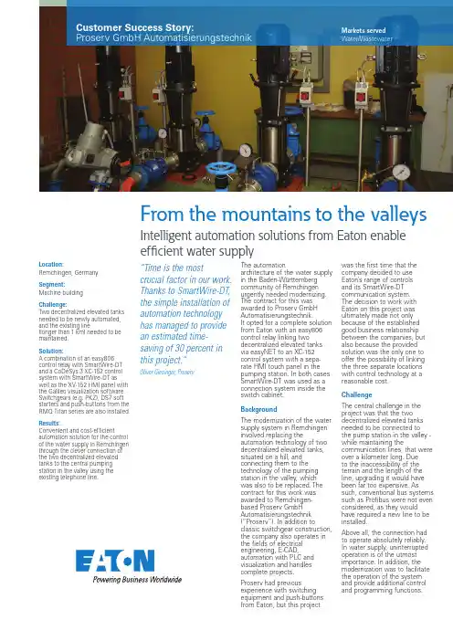
From the mountains to the valleys Intelligent automation solutions from Eaton enable efficient water supplyLocation:Remchingen, Germany Segment:Machine buildingChallenge:Two decentralized elevated tanks needed to be newly automated, and the existing line(longer than 1 km) needed to be maintained.Solution:A combination of an easy806 control relay with SmartWire-DT and a CoDeSys 3 XC-152 control system with SmartWire-DT as well as the XV-152 HMI panel with the Galileo visualization software. Switchgears (e.g. PKZ), DS7 soft starters and push-buttons from the RMQ Titan series are also installed. Results:Convenient and cost-efficient automation solution for the control of the water supply in Remchingen through the clever connection of the two decentralized elevated tanks to the central pumping station in the valley using the existing telephone line.“Time is the mostcrucial factor in our work.Thanks to SmartWire-DT,the simple installation ofautomation technologyhas managed to providean estimated time-saving of 30 percent inthis project.”Oliver Giesinger, ProservThe automationarchitecture of the water supplyin the Baden-Württembergcommunity of Remchingenurgently needed modernizing.The contract for this wasawarded to Proserv GmbHAutomatisierungstechnik.It opted for a complete solutionfrom Eaton with an easy806control relay linking twodecentralized elevated tanksvia easyNET to an XC-152control system with a sepa-rate HMI touch panel in thepumping station. In both casesSmartWire-DT was used as aconnection system inside theswitch cabinet.BackgroundThe modernization of the watersupply system in Remchingeninvolved replacing theautomation technology of twodecentralized elevated tanks,situated on a hill, andconnecting them to thetechnology of the pumpingstation in the valley, whichwas also to be replaced. Thecontract for this work wasawarded to Remchingen-based Proserv GmbHAutomatisierungstechnik(“Proserv”). In addition toclassic switchgear construction,the company also operates inthe fields of electricalengineering, E-CAD,automation with PLC andvisualization and handlescomplete projects.Proserv had previousexperience with switchingequipment and push-buttonsfrom Eaton, but this projectwas the first time that thecompany decided to useEaton’s range of controlsand its SmartWire-DTcommunication system.The decision to work withEaton on this project wasultimately made not onlybecause of the establishedgood business relationshipbetween the companies, butalso because the providedsolution was the only one tooffer the possibility of linkingthe three separate locationswith control technology at areasonable cost.ChallengeThe central challenge in theproject was that the twodecentralized elevated tanksneeded to be connected tothe pump station in the valley -while maintaining thecommunication lines, that wereover a kilometer long. Dueto the inaccessibility of theterrain and the length of theline, upgrading it would havebeen far too expensive. Assuch, conventional bus systemssuch as Profibus were not evenconsidered, as they wouldhave required a new line to beinstalled.Above all, the connection hadto operate absolutely reliably.In water supply, uninterruptedoperation is of the utmostimportance. In addition, themodernization was to facilitatethe operation of the systemand provide additional controland programming functions.Customer Success Story:Proserv GmbH Automatisierungstechnik Markets servedWater/WastewaterEatonEMEA Headquarters Route de la Longeraie 7 1110 Morges, Switzerland Eaton.eu© 2015 EatonAll Rights Reserved Publication No. CS083046EN November 2015Eaton is a registered trademark. All other trademarks are property of their respective owners.SolutionEaton’s easyNET network solves several challenges at once. Firstly, the technology meets the most important condition, namely that the existing telecontrol line could also be used for the new automation solution - an important cost factor. Dueto the particular installationin the mountainous area and the length of the line, Proserv and Eaton conducted their own functionality tests before commissioning to ensure that the communications securityof easyNET would always be ensured, even with cables not supplied by them and over such a distance.In addition, easyNET servesas an intermediary between two worlds. The system, based on the CAN network, enables an exchange of process and system data,and is capable of connecting eight network devices (e.g. controllers). It combines two types of network participants with different programming- namely ones from the easy-world (programming in the form of a circuit diagram) and controls from the IEC standard (programming according to IEC 1131). In Remchingen,the solution consists of the decentralized easy806 control relay for the elevated tanks and the XC-152 controller basedon CoDeSys 3 with a separate 10.4” XV-152 HMI touch panel in the pumping station located in the valley. The visualization of the HMI panel is achieved using Eaton’s Galileo software.“It was our first project witha control system based on CoDeSys. As an experienced automation technician, a four-hour foundation course from Eaton was enough for meto write the control program for the application. The pre-programmed functional blocks, which were delivered withthe control system, were very helpful here. It makes life a lot easier to not have to program everything manually and saves a considerable amount oftime in comparison to similar systems. Galileo was also new to me. But again, I foundthe programming simple,”explains Oliver Giesinger, oneof Proserv’s two managingdirectors.Further automationcomponents such asswitching devices andpush-buttons from the RMQTitan series are connectedto the XC-152 controller viaSmartWire-DT. Various diagnos-tic and status messages withreadout capability are madeavailable to the user throughthe starter combination (DS7soft starter and PKZ manualmotor starter). Individual deviceparameters can thus be readand (over)written. Various I/Omodules are also connectedwith SmartWire-DT to theeasy806 control relay. Whererequired, this modular structurecan be extended flexibly andwith a minimum of effort.“At first I was skeptical aboutSmartWire-DT, but the systemhas won me over. Mostlybecause of the unbelievableamount of time that it saves.It only took about an hour toinstall all of the SmartWirecomponents. An added bonuswas that SmartWire-DT keptwiring errors to a minimum andenabled further usefulfunctions that conventionallywould only be implementedin much more complex andexpensive systems,” continuesGiesinger.ResultsThe automation solution fromEaton, with the unique mixof simple, easy control relaysand individually programmableCoDeSys control systemswith a clear display, is bothcost-efficient and user-friendly.Costs were saved as a new linebetween the elevated tanksand the pumping station didnot have to be laid. Comparedwith conventional solutions,SmartWire-DT significantlyreduces the installation costsfor all automation technology.Furthermore, the startercombinations increase systemavailability by transmittingprocess-related data - e.g.motor current or switch setting- and Eaton’s communicationsystem saves the user fromtime-consuming troubleshoot-ing during commissioning andmaintenance.“Time is the most crucialfactor in our work. Thanksto SmartWire-DT, the simpleinstallation of automationtechnology has managed toprovide an estimated time-saving of 30 per cent in thisproject. Of course, the enduser also profited from this,as he had to pay us for lessman hours. I’m so impressedby SmartWire-DT that wewould also like to offer thissystem to other customers,”says Giesinger. “I can onlyrecommend Eaton, both for thequality of their products andwith regard to sales support.I work with all of the majormanufacturers of automationcomponents in Germany, butI’ve not received such goodsupport in 25 years.”The complex wiring of earlier days.The new streamlined automationusing modern technology fromEaton. It is clear which switchcabinet the plant manufacturerwould prefer to work on.Convenient for the user: Errormessages are sent by text messageand the system can be easily moni-tored and controlled via smartphoneor tablet.。
C-NaviGator Software Update Installation ProcedureRevision 5Revision Date: July 30, 2018C-Nav® Positioning Solutions730 E. Kaliste Saloom RoadLafayette, LA 70508 U.S.A./cnavC-NaviGator Software Update Installation ProcedureRelease NoticeThis is the July 2018 release of the C-NaviGator Software Update Installation Procedure.Revision HistoryC-NaviGator Software Update Installation ProcedureTrademarksThe Oceaneering logo is a trademark of Oceaneering International, Inc. C-Nav is a trademark of Oceaneering International, Inc. All other brand names are trademarks of their respective holders.Disclaimer of WarrantyEXCEPT AS INDICATED IN “LIMITED WARRANTY” HEREIN, OCEANEERING INTERNATIONAL, INC. SOFTWARE, FIRMWARE AND DOCUMENTATION ARE PROVIDED “AS IS” AND WITHOUT EXPRESSED OR LIMITED WARRANTY OF ANY KIND BY EITHER OCEANEERING INTERNATIONAL, INC., OR ANYONE WHO HAS BEEN INVOLVED IN ITS CREATION, PRODUCTION, OR DISTRIBUTION INCLUDING BUT NOT LIMITED TO THE IMPLIED WARRANTIES OF MERCHANTABILITY AND FITNESS FOR A PARTICULAR PURPOSE. THE ENTIRE RISK, AS TO THE QUALITY AND PERFORMANCE OF THE OCEANEERING INTERNATIONAL, INC. HARDWARE, SOFTWARE, FIRMWARE AND DOCUMENTATION, IS WITH YOU. SOME STATES DO NOT ALLOW THE EXCLUSION OF IMPLIED WARRANTIES, SO THE ABOVE EXCLUSION MAY NOT APPLY TO YOU. Limitation of LiabilityIN NO EVENT WILL OCEANEERING INTERNATIONAL, INC., OR ANY PERSON INVOLVED IN THE CREATION, PRODUCTION, OR DISTRIBUTION OF THE OCEANEERING INTERNATIONAL, INC. SOFTWARE, HARDWARE, FIRMWARE AND DOCUMENTATION BE LIABLE TO YOU ON ACCOUNT OF ANY CLAIM FOR ANY DAMAGES, INCLUDING ANY LOST PROFITS, LOST SAVINGS, OR OTHER SPECIAL, INCIDENTAL, CONSEQUENTIAL, OR EXEMPLARY DAMAGES, INCLUDING BUT NOT LIMITED TO ANY DAMAGES ASSESSED AGAINST OR PAID BY YOU TO ANY THIRD PARTY, RISING OUT OF THE USE, LIABILITY TO USE, QUALITY OR PERFORMANCE OF SUCH OCEANEERING INTERNATIONAL, INC. SOFTWARE, HARDWARE, AND DOCUMENTATION, EVEN IF OCEANEERING INTERNATIONAL, INC., OR ANY SUCH PERSON OR ENTITY HAS BEEN ADVISED OF THE POSSIBILITY OF DAMAGES, OR FOR ANY CLAIM BY ANY OTHER PARTY. SOME STATES DO NOT ALLOW THE LIMITATION OR EXCLUSION OF LIABILITY FOR INCIDENTAL OR CONSEQUENTIAL DAMAGES SO, THE ABOVE LIMITATIONS MAY NOT APPLY TO YOU.C-NaviGator Software Update Installation ProcedureTable of ContentsTrademarks (3)Disclaimer of Warranty (3)Limitation of Liability (3)Table of Contents (4)Manual Organization (5)Manual Conventions (6)Section 1 - Overview (7)Introduction (7)Section 2 - Required Items (8)Software Update (8)Rescue Install (8)Section 3 - Software Update (9)Section 4 - Rescue Install (10)C-NaviGator Software Update Installation ProcedureManual OrganizationThe purpose of this document is to provide instruction on the installation of software updates for the C-NaviGator touch-screen Control and Display Unit (CDU) using a USB Drive. Sections are organized in a manner that facilitates quick operator orientation.Section 1 - Overview (Page 7) gives a brief overview of the purpose of this document.Section 2 - Required Items (Page 8) lists the items required to perform both a software update and a rescue install.Section 3 - Software Update (Page 9) describes a normal software update procedure.Section 4 - Rescue Install (Page 10) describes the procedure to use the rescue installer to recover a corrupt software installation.C-NaviGator Software Update Installation ProcedureManual ConventionsArial font is used for plain text in this document.Arial italic font is used for settings names.“Arial quoted” font is used for settings values.Arial Bold font is used for button names.Arial Bold Italic font is used for menu items.Arial Blue font is used for cross-references.Arial Blue Underline font is used for hyperlinks.Arial red italic is used for typed commands.Arial Bold font size 10 is used for captions.ARIAL BLACK ALL-CAPS font is used for port connection names.This symbol means Reader Be Careful. It indicates a caution, care, and/or safety situation. The user might do something that couldresult in equipment damage or loss of data.This symbol means Danger. You are in a situation that could cause bodily injury. Before you work on any equipment, be aware of thehazards involved with electrical and RF circuitry and be familiarwith standard practices for preventing accidents.Important notes are displayed in shaded text boxes.Simple file content is displayed in Courier New Black font in a text box.C-NaviGator Software Update Installation ProcedureSection 1 - OverviewIntroductionThe purpose of this document is to provide instructions on the installation of software updates for the C-NaviGator touch-screen Control and Display Unit (CDU) using a USB Drive. To obtain copies of C-Nav® software updates, contact C-Nav® Support (***************************) or visit /cnav.C-NaviGator Software Update Installation ProcedureSection 2 - Required ItemsSoftware Update∙C-NaviGator CDU∙USB drive (>100 MB) formatted as FAT (not NTFS)∙Software Update cng or cng3 file, available by contacting C-Nav® Support or by visiting /positioning-solutions/customer-access-and-resources/∙ A Windows PCRescue Install∙C-NaviGator CDU∙USB drive (>100 MB) formatted as FAT (not NTFS)∙USB keyboard to connect to the C-NaviGator∙Software Update zip file, available by contacting C-Nav® Support or by visiting /positioning-solutions/customer-access-and-resources/∙ A Windows PC and WinZip or equivalent file extraction softwareC-NaviGator Software Update Installation ProcedureSection 3 - Software Update1. Contact C-Nav® Support or visit /positioning-solutions/customer-access-and-resources/ to obtain the latest softwareupdate for the C-NaviGator. Download the firmware file to the top-levelfolder of the USB.A. For the C-NaviGator II, the firmware file will be a .cng file.B. For the C-NaviGator III, the firmware file will be a .cng3 file.2. Attach a USB drive to the Windows PC.3. Ensure the computer has finished writing to the USB drive (use the SafelyRemove Hardware tray icon if necessary) then remove the USB drive from the computer.4. Reboot the C-NaviGator.5. When the boot menu appears, press the Update Software button.6. Connect the USB drive to the C-NaviGator.7. Press the Scan USB button to scan for the software update file.8. In the C-NaviGator Software Update table, select the firmware with aStatus of “compatible”.9. Press Start Update.10. When the installation is complete, press Restart to continue.11. The C-NaviGator software update is now complete.C-NaviGator Software Update Installation ProcedureSection 4 - Rescue InstallThe C-NaviGator CDU rescue installation is a procedure to recover a corrupt software installation. This should only be used as a last resort if regular a software update cannot be completed.1. Contact C-Nav® Support or visit /positioning-solutions/customer-access-and-resources/ to obtain the latest rescueinstaller for the C-NaviGator. Download the zipped file to the local drive of the Windows PC.2. Attach a USB drive to the Windows PC.3. Using WinZip or equivalent Windows file extraction software, extract thezipped file into the top-level folder of the USB drive. This will create afolder called syslinux when complete.4. Install the rescue installer onto the USB drive. The steps are differentdepending on what version of Windows the PC is running.A. Windows XP:I. Open the USB drive on the Windows PC via My Computerand navigate into the syslinux folder.II. Double-click on the file called install.bat. A commandprompt window will pop up to show the results. Press Enterto continue.B. Windows 7I. Click on the Start Menu button.II. In the Search bar, type cmd, then press Ctrl+Shift+Enter(all at the same time). This will open a command promptwindow with Administrator rights.III. Type DRIVE_LETTER: and press Enter. WhereDRIVE_LETTER is the drive letter of the USB drive.C-NaviGator Software Update Installation ProcedureIV. Type cd syslinux and press Enter.V. Type install.bat and press Enter.VI. Once finished, press Enter and close the command promptwindow.5. Ensure the computer has finished writing to the USB drive (use the SafelyRemove Hardware tray icon if necessary) then remove the USB drive from the computer.6. Power off the C-NaviGator via the front panel On/Off switch.7. Connect the USB keyboard to the C-NaviGator and disconnect all otherUSB devices from the C-NaviGator.8. Connect the USB drive to the C-NaviGator.9. Turn on the C-NaviGator.10. The next step is to boot the C-NaviGator CDU off of the USB drive. Thesteps are different depending on which type of C-NaviGator CDU.A. C-NaviGator II:I. When the blue C-Nav logo screen appears, hit Delete on thekeyboard. This will open C-NaviGator CDU’s BIOSconfiguration screen. If the BIOS configuration screen doesnot appear, power off the C-NaviGator and try again.II. At the main BIOS configuration screen, select AdvancedBIOS Features. Within that screen, set First Boot Device to“USB-ZIP”. All other boot devices should be set to“Disabled”. Press F10 to save and exit the BIOS screen.B. C-NaviGator III:I. When the screen appears, press F11 on the keyboard.Continue to press F11 until the boot-device menu appears.C-NaviGator Software Update Installation ProcedureII. Select the device that starts with USB and press Enter.11. The C-NaviGator will now boot off of the USB drive. Messages will printon the C-NaviGator screen from the installation program; it will take a few seconds for the installation program to locate the appropriate files on theUSB drive. When complete, press Enter to begin the installation.12. When the installation is complete, press Enter or touch the screenanywhere to continue.13. At this point the C-NaviGator will prompt the user to turn off the unit. Doso via the front panel On/Off switch and disconnect the USB drive.14. The following step applies only to the C-NaviGator II.A. When the blue C-Nav® logo screen appears, hit Delete on thekeyboard. This will open C-NaviGator CDU’s BIOS configurationscreen. If the BIOS configuration screen does not appear, poweroff the C-NaviGator and try again.B. As before, select Advanced BIOS Features. Within that screen, setFirst Boot Device to “Hard Disk”. Leave the other boot devices as“Disabled”. Press F10 to save and exit the BIOS screen.15. The C-NaviGator rescue installation is now complete.。
[I B 1 Sha 2 Pur 3 Adj 4 Put 5 Leg 6 AE 7 Out 8 Inst 9Inst AppendixAcronym AE AEGs ALT AMT AOC NOP OKS PAA R/O TCE TOCnsert O riefing aring of risk/o rpose of this ustment Eve tting risk allo gal/contractu alignment p tline for the A tructions for tructions for 1: Owner’s T ms in this do Adjustmen Adjustmen Alliance Le Alliance M Actual Out Non-Owne Overall KR Project Alli Risk/oppor Target Cos Target OutOwner O on Ad opportunity –briefing pap ents – comm cation in per ual context – rocess overv AE alignmen completing t returning the Team Attend cument nt Event nt Event Guid eadership Te anagement T tturn Cost er Participant RA score iance Agreem rtunity st Estimate tturn Cost Organiz djustme – setting the er ...............ercial contex rspective .....why the AE view ............nt workshop a the questionn e completed dees ............delines eam Team t mentzation][ent Eveoverall conte ....................xt .....................................Guidelines r ....................and who sho naire ............questionnair ....................Insert N ent alig ext ...........................................................................really matter .....................ould attend .......................res o gnmen ........................................................................................................................................................................................................of Proje t proce ........................................................................................................................................................................................................ect] ess...........2 ...........2 ...........3 ...........4 ...........5 ...........6 ...........7 ...........9 (10) (11)1Sh 1.1Und Allia be 1.2All hav1.3The to r 1.4Wh cult con per 2Pu 2.1The be 2.2Spe(a) (b) (c) (d)2.3 Not Sceharing of r der the ‘3-lim ance Particip borne unilate risk/opportu ve agreed are e ‘Adjustmen reached infor hile focussed tural alignm nventional ris rformance is urpose of t e legal/comm developed d ecifically, this explains provides performa describes andprovides te that it is enario Quest isk/oppor mb’ compens pants) or reta erally by the nity is share e retained un nt Event alig rmed alignm d primarily o ment. The p sk-transfer m the norm.this briefin mercial conte during the All s briefing pap the contractu guidance on ance alliance s the AE alig instructions essential yo tionnaire.rtunity – se sation frame ained unilate Non-Owner ed collectivel nilaterally by nment proce ent on what on commerc rocess is d mindset to an ng paperext of the Adj iance Develo per: ual/commerc n the comme ; gnment proce for completin ou read this etting the work, risk/op erally by the Participants ly except for y the owner.ess’ describe risks/opportu cial alignmen designed to alliance min justment Eve opment Phas cial context o ercial rationa ess and conf ng and return s briefing pa overall co pportunity is Owner. The (NOPs). r those types ed in this bri unities will be nt the proce facilitate a ndset and a ent Guideline se are set ou of Adjustmen ale for the tre firms the logi ning the atta aper thoroug ontexteither share ere is no opti s of risk/opp efing paper e borne unila ess is as m radical an “one-team” e es and the pr ut in this brief t Events (AE eatment of ri stics for the ched ‘Scena ghly before s ed collectivel on for risk/op portunity the enables the aterally by th uch, if not m d rapid tran environment rocess by wh fing paper. Es);sk/opportuni AE alignmen ario Question starting to c ly (by all the pportunity to participants participants e owner. more, about nsition from where high-hich they will ity in a high-nt workshop,nnaire’.complete the e o s s t m -l -,e3Ad 3.1The Eve gai 3.2AsR/O col par R/O uni Ow 3.3The pro will wheuni djustment e diagram b ent (AE) nee nshare/pains noted aboveOptionO is shared lectively by t rticipants O is borne ilaterally by t wner e default pre ovisions for r be conside ere the ass laterally by th Events – elow illustra eds to be con share regime e, there are o the ∙ Pro Est coll ∙ If th Out the ∙ If th targ imp ∙ It is the Ow ∙ The the esumption is isk/opportun red to be an sociated risk he Owner.commerc ates the NOP nsidered in t e.only two optio Com ovisions for ri timate (TCE)lectively by t he risk/oppor tturn Cost (T he risk/oppor gets may nee pact. In other s not required TCE for risk wner.e Owner will net costs as that all risks ity within the n Adjustment k/opportunity ial contex P compensa the context o ons for how r mmercial an isk/opportun ) consistent w he participan rtunity eventu TOC) or any o rtunity eventu ed to be adju r words, it is d or appropr ks (or opportu need to mak ssociated wit s/opportunitie e TCE the p t Event (AE)y, should th xtation framew of this comp risk/opportun nd administr ity must be i with the risks nts. uates there i of the non-co uates then th usted, consis an Adjustme iate to allow unities) that ke an allowa th Adjustmen es are share participants m ) i.e. they m hose circum work. The co ensation mo nity (R/O) is s rative implic ncluded in th s/opportunitie s no adjustm ost targets. he TOC and/stent with the ent Event. any provisio are being bo nce, separat nt Events.ed. In order t must align on ust agree th mstances ev oncept of an odel and in p shared/alloca cationshe Target Co es being born ment to the T /or non-cost e agreed ass ons in the bui orne unilatera te from the T to be able to n what situat he circumsta ventuate, wi Adjustment particular the ated: ostne argetlimb 3ociated ild-up ofally by the TCE, for o finalise the tions, if any,nces, if any,ll be borne t e e, , e4Pu 4.1It is risk bala4.2The dia (a)(b)4.3At t and sha utting risk s important to k/opportunity ance betwee Increas risk/opp retained ProsLower TOC - minimal provisio for risk included within TCEe decisions a l’ towards eit The furth more rob upwards The upwa the risk/o left). The the comm adversar the AE align d Proponent)aring of risk/a allocation o understand y should be s en two extrem sing number o portunity items d by the Owne C ond Expecthigh ad High pdispute Negati unfoldiOwner Higher at the AE alig ther end of th her to the rig bust will be th pressure on ard pressure opportunity is e more you tu mercial foun ial form of co ment worksh ) clearly und allocation.n in persp d that there i shared collec mes, as illust ofs rCons t lots of AEs, dmin otential for e ve events ing = r’s risk r AOC (?)gnment work he spectrum ght the dial he ‘one team the TOC.e on the TOC s retained u urn the dial a ndation of th ontract.hops we will derstandsthe ectives no ‘right’ o ctively or reta trated in sim The ris sharing/allo ‘dial’kshop(s) can – in this res is turned (ie m’ foundation C can be eas nilaterally by away from fu he alliance, s explore this eimplication or ‘wrong’ ap ained unilate plistic terms skocation’n be likened spect:e. more risk/ of the allian sed by increa y the Owner ull risk/oppor shifting it ba concept furt ns ofmoving proach, and rally by the O in the follow All/morisk/o sharePros Little/no enadmin of AE All risk/opp shared ‘obehaviour’ Lower AOC to turning th /opportunity nce. The dow asing the num r (ie. turn th rtunity sharin ack towards ther so that g the dial(tothe decision Owner involv wing diagram:ost pportunity is ed collectively sergy on Esortunityone team’ C (?)Hi c w he ‘risk sharin shared colle wnside is that mber of situa e dial back ng the more a traditiona the whole gr o the left) aw n on whether ves striking a :Cons Higher TOC – increased contingency within TCEng/allocation ectively), the t this will put ations where towards the you weaken al potentially roup (Owner way from full r a net e e n y r l5Le 5.1Cla clea 12.12.5.2Givin d 5.3The Typ rise (a)(b)gal/contra ause 12 of t arly: 2The Pa Alliance 12.2.1 t 12.2.2 t them; o 12.2.3 a except that the indicate 3 ThePa 12.3.1 t opportu 12.2.2 t opportu 12.2.3 t retained elsewhe ven this legal determining a ere are time pically, in eac e to the misa Key playeAdjustme which ma mean tha they faile such ass There wasame un the Adjusactual con the draft PA articipants h e Works, reg those risks o the Participa or any provision for those ris e Participan ed in the Adju rticipants ack the types of s unity is share the types of s unity is retain there are no d unilaterally ere in this Ag l context the and clarifying es when the ch of those c lignment:ers involved ent Event Gu any of the k at an Adjust ed to have re umptions an as little or no derstanding stment Eventntext – wh AA sets out have agreed gardless of w or opportuniti nts could (or n was made sks or oppor nts have spe ustment Eve knowledge th scenarios in ed are not ex scenarios in ned unilateral other types y by the Own greement to guidelines d g how risk/op ALT is una cases the fo in developin uidelines. Ty key players, ment Event egard to the A nd therefore b o attempt to of the Adjus t alignment w y the AE G the legal co d to share a whether: ies are within r should) rea for them in t rtunities (or p ecifically agr ent Guideline hat: the Adjustm xhaustive; the Adjustm lly by the Ow of events or er, except fo be an Adjust developed at pportunity wi able to reac llowing root ng the TCE f ypically, the T more accust would apply Adjustment E by default, w ensure that stment Event workshop(s).Guidelines ontext of the all risks and n the control asonably hav the Target O portions of s reed will be s.ment Event G ment Event G wner is exhau circumstanc or events or c tment Event.the AE align ll be shared ch agreemen causes (amo failed to gras TCE/TOC re tomed to co y if the assu Event Guide were a shared t new/replace t Guidelines s really m e Adjustment d opportuniti of the Partic ve foreseen o utturn Cost,such types o e retained s uidelines for uidelines for ustive; and ces for which circumstance .nment works amongst the nt on contes ongst others sp the signifi eport contain onventional te umptions pro elines which d risk/opportu ement memb as the peop attert Event Guid ies associat cipants;or made allow of risks or op solely by the r which a risk r which a risk a risk or opp es expressly hop(s) play a e participants sted Adjustm ) are signific icance/impor ed lists of ‘a endering, tho oved to be in made no me unity. bers of the A ple who were delines very ted with the wance for pportunities)e Owner as k or k or portunity is stated a critical role s. ment Events.cant in giving rtance of the assumptions’ought would ncorrect. But ention of any ALT had the e involved in y e) s e . g e ’ d t y e n6AE 6.1Sel com whe coll 6.2Ple alig own 6.3A [Pro trea wor 6.4Ide forw use maj hav Thi eva 6.5The [Insert Al E alignmen ected perso mplete and re ether the ris lectively (by ease note tha gnment proce nership of th Insert Name oponent, see ated as an A rkshop to en ally, based o ward a singl e it as the Ad jor divergen ve a differen rd Party Est aluating the t e timeline for ignment Pro nt process nnel from th eturn the att sk (or oppor all Participan at getting ind ess, in order e agreed out e of Alliance eking to reac AE. It may b able the grou on the respe e set of Adj djustment Ev ce between nt set of AE timator, will two Project P r the alignme cess Schedu s overview he Owner an tached Scen rtunity) in ea nts) or retain dividual, not r to ensure t tcome – i.e. Facilitator]-ch alignment be necessary up to reach a ective output ustment Eve vent Guidelin the risk/opp Guidelines f make an al Proposals. ent process is ule Graphic]wd each Prop ario Questio ach of the h ed unilateral corporate, p the level and we want you -facilitated al t for each h y to hold a alignment on s of the alig ents Guidelin nes (to form portunity app for each Pro lowance for s shown belo ponent, throu onnaire giving hypothetical lly by the Ow erspectives d quality of ur personal v lignment wo ypothetical s shorter follow n all scenario nment works nes seeking part of Sche petite of the oponent. In t the differen ow:ugh this brief g their perso scenarios w wner (i.e. an A is fundamen understandin view, not the rkshop will b scenario whe w-up worksh os. shops, the O agreement edule 5 of th two groups that case th nce in risk/o fing paper, a onal/individua would/should Adjustment E ntal to the int ng, debate a ‘corporate p be conducte ether or not hop soon aft Owner will be from each P he PAA). Wh it may be n e Owner, gu pportunity p are asked to al view as to d be shared Event). tegrity of the and eventual osition’. ed with each it would be ter the main e able to put Proponent to here there is necessary to uided by the rofiles when o o d e l h e n t o s o e n7Ou 7.1The info 7.2 The 7.3Thi as aCom tim D a y 1, [I n s e r t D a t e ]1234D a y 2, [i n s e r t D a t e ]5 6a6b7D a y 3, [I n s e r t D t ]8 9autline for t e overall pu ormed set of e workshop w s workshop a contingenc mmencing [I me] . A draft s 14.00 Pre 14.30 Fra wo 15.45 Bre 16.00 On rev alig 17.30 Sum pro 18.00 Da 14.00 Set 14.20 On rev alig 15.45 Bre 16.00 On rev alig 17.30 Sum clo 18.00Da 14.00 Set 14.20 On revthe AE alig rpose of the draft Adjustm will be facilita will be held cy in case ex Insert Date]sample agen eliminariesaming theorkshopeak screenview and gnmentmmariseogressay 1 closet up day 2 screenview and gnmenteak screenview and gnmentmmarise andse out ay 2 closet up day 3 screenview and gnment wo e AE alignm ment Event G ated by[Inser over 3 x ha xtra time is ne starting at [da is set out ∙ Opening ∙ Confirm ∙ Set up fo parking ∙ Review c ∙ Commer foundat ∙ Align on ∙ Process ∙ Work th or not it ∙ Review ∙ Reflect &∙ Insights ∙Overnig ∙ Team ch ∙ Agree pr ∙ Work th or not it∙ Work th or not it ∙ Review ∙ Reflect &∙ Overnig ∙ Review a ∙ Agree pr ∙ Work th or not it orkshop a ment worksh Guidelines. rt Name of A alf-day sessio eeded): [Insert time](t below: g comments, b purpose and or effective co lot) and confi compensation rcial context –ion. n expectations briefing rough and aim t would consti Day 1 progres & correct exer and lessons f ht actions / re heck in & revie riorities for us rough and aim t would consti rough and aim t would consti Day 2 progres & correct exer ht actions/req any overnight riorities for us rough and aim t would consti and who s op with eac Alliance Facili ons [Insert L (sharp) and a brief introduc agenda for th onversations, rm commitme n framework a – there is no ‘s of each othe m to reach alig itute an Adjus ss and remain rciserom this sessi equestsew any overni se of remainin m to reach alig itute an Adjus m to reach alig itute an Adjus ss & behaviou rcise questst actions se of remainin m to reach alig itute an Adjus should atte ch Proponen itator].Location](with aiming to fin tions, housek his workshop agree protoco ent to particip and putting A right’ answer.er at this work gned view for stment Event ing scenarios ion ight actionsng timegned view for stment Event gned view for stment Event rs ng timegned view for stment Eventendnt is to align h a 4th half-d nish no later keepingols (conduct, pate positively Es in proper p . Co‐creating kshop r each scenari r each scenari r each scenari r each scenari n on a well-day reserved than [insert outputs, y perspective the right o whether o whether o whether o whether -d t9b10Day 4 [Inse7.4 Wefou7.5 Proguidwho7.6 Thecoma va(a)(b)(c)7.7 NOScecomcomalig15.45 Bre16.00 Onrevalig17.30 Sumclo18.00 Dayert Date]e expect thatrth session aoponents aredance provido will be attee workshop smmercial rolealuable contGiven thaan AE, itIn practicof circum(AMT) beAllianceleadershiProponenpeople wHoweverOTE* - It is aenario Questmpleted/returmplications ingnmenteakscreenview andgnmentmmarise andse outy 3 / workshopt only theseavailable as ae invited to bded below. Pending.should be ate in the estabribution to that in most inis expectedce, once themstances justefore beingProject Manip role in thents can chowho will be rer, legal represa requirementionnaire (refrned the Scento the proce∙Work thor not it∙Review s∙Reflect &∙General∙Overnigp closee 3 half-daya contingencring a total oProponents attended by thblishment anhe conversatinstances it wthat all nomialliance is utifies an AE wreferred tonager and ralliance atteoose to bringesponsible fosentation atnt that eachfer instructioenario Questess.rough and aimt would constistatus & confi& correct exerfeedback andht actions/reqPlacehosessions wicy.of between 1are requiredhose who nend/or deliveryion. In this rewill be the ALinated Propounder way itwill initially tathe ALT. Oelevant nomend this workg membersor the Projecthis workshoperson atteons below). Htionnaire or vm to reach aligitute an Adjusirm next stepsrcised residual issuquests (if contolder if requireill be require0 and 12 ped to confirmeed to be invy of the allianespect:LT that deteronent ALT mis expectedake place wiOn that basisminees for thkshop.of their comct Proposal Top is not expeending the wHaving peopvice versa ingned view forstment Eventsuestinuing to dayeded but particeople to the win writing novolved becaunce along wirmines whethembers attenthat the discthin the Allias it is expeche AMT andmmercial anTCE developected or requworkshop cople attend thetroduces unhr each scenariy 4)cipants shouworkshop ino later than [use they havith others whher circumstand.cussion on wance Managected that thed those withnd estimatingpment) to thuired.mpletes ande workshophelpful and uo whetheruld keep theline with the[Insert Date]ve a relevantho can makeances justifywhether a setement Teame nominatedh a relevantg team (i.e.e workshop.d returns thewho haven’tunnecessaryee]teytmdt..ety8Ins 8.1The _Mthe Pro 8.2Inse sele of t 8.3Forind be (co give as t 8.4Bel sce thin des of d 8.5The Ple newstructions e questionna yName.xlsx ) filename w oponent Nam ert your full ect from the he ALT, click r each of th icate (by ins treated as alumn F). Avoe full details the concept ow the [Ins enarios (A, B nk there mig scription that detail as in th e spreadshee ease do not re w row or rem Please no ‘rig s for comp aire is provide ). The first st ith your nam me]_ [insert n name in ce drop-down l k on cell E2 a e[Insert Num erting a ‘1’ in an Adjustmen oid using co in column F of an Adjustm sert Number B) covering s ght be misali t clearly expl he set scena et is protecte emove the p move rows).e complete a ght’ or ‘wrong wo pleting the ed as an Exc tep is to save me - eg. [Ins name] .xlsx .ll B2, your i list which org and select “A mber of Sce n column C, nt Event (AE olumn E (‘?’ F. [Note: - as ment Event o r of Scenari situations tha ignment. If y ains the con rios). ed so you ca protection or ** NO nd return the g’ answers. ork with othe e question cel spreadsh e the file un sert Name] w nitials in cel ganisation yo ALT”, if not le enarios]set s D or E) whe E). Give reas indicating ‘D sume that ea only comes i ios] set sce at are not al you do inser ntext, cause n only edit ce try to change OTE –very e questionna Please do no ers to respon nnaireheet (CDHRP nder a new n would save t l C2 (please ou represent eave cell E3 scenarios, re ether or not y sons for you Depends’) if ach scenario into play afte enarios, you lready cover rt extra scen and associa ells that are e the structu important **aire on your ot check you d to the ques P_AEG_Q1-[name replac the file as: C e use 3 lett t. If you are n blank. ead the scen you think tha ur answer in possible but o occurs afte er the TOC is may insert red by the se narios pleas ted implicatio intended to b re of the spre *own – reme ur responses stionnaire.[Insert Propo cing the “My.CDHRP_AEG ters ), click o nominated a nario carefu at situation s the ‘Comme if you do us er the TOC is s locked in.] t one or tw et scenarios e ensure yo ons (with the be user chan eadsheet (e.mber there a with others onent Name]Name ” bit of G_Q1-[Insert on cell D2 to as a member lly and then should/would ents’ column se it, please s locked in –wo additional s, where you ou provide a e same level ngeable. .g. insert are or] f t o r n dn e – l u a l9Ins 9.1 E-m 9.2The no (a) (b)9.3If y Constructions mail your com e Proponent later than [In a list of th for each you have any ntact Person s for return mpleted (rena Contact Rep nsert Date] co hose who wil person atten y technical p n.ning the c amed) Excel presentative omprising:ll be attendin nding the wor problems with ompleted file to Propo is required t ng the works rkshop a com h the spread question onent Contac to submit an hop, andmpleted indiv dsheet, pleas nairesct Represent e-package t vidual Excel Q se have you tative.to the Contac Questionnair r query forw ct Person by re.arded to the y eAppendixNamFacilx 1: Owne elitators & Ober’s Team bserversAttendees RoleAlliance Fa Alliance Fa Third Party Fairness Rsacilitator acilitator y Estimator eviewerOr[In Al Fa [In Al Fa [In Th Es [In Fa Re Strictl rganisationnsert Name o lliance acilitator] nsert Name o lliance acilitator] nsert Name o hird Party stimator] nsert Name o airness eviewer]y ConfidentialPage 11ofof of ofl。
Contents: Series 33 (3-Way), 43 (4-Way), 53 (5-Way) MULTI-PORT BALLVALVESBRIEF INTRODUCTION (2)INSTALLATION (2)Installation of Threaded End Valves (2)(33-TH/43-TH/53-TH) (2)Installation of Welded End Valves (2)(33-SW/43-SW/53-SW OR 33-BW/43-BW/53-BW) (2)Installation of Flanged End Valves (2)(33-F1/43-F1/53-F1 OR 33-F3/43-F3/53-F3) (2)Installation of Hygenic Clamp/Sanitary Ends (2)(33-SA/43-SA/53-SA OR 33-SF/43-SF/53-SF) (2)OPERATION (2)Automation Operation (3)MAINTENANCE (3)Table 1: Body Bolt Torque (3)Table 2: Stem Nut Torque (4)Seat Kit & Repair Kit Part Numbers (4)Materials List (6)BRIEF INTRODUCTIONA-T Controls Multi-Port high performance ball valves have been designed and engineered with five seats for equal loading and sealing at any port to provide long lasting and trouble free service when used in accordance with the instructions and specifications stated in this document.WARNINGFOR YOUR SAFETY, IT IS IMPORTANT THAT THE FOLLOWING PRECAUTIONS BE TAKEN BEFORE REMOVAL OF THE VALVE FROM THE LINE OR ANY DISASSEMBLY.1. Wear protective clothing and equipment whenworking with potentially harmful fluids.2. Depressurize the line and cycle the valve asfollows:a. Place the valve in the open position anddrain the line.b. Cycle the valve to relieve residualpressure in the body cavity beforeremoval from the line.c. Allow valve to cool if valve is used inhigh temperature applications.d. After removal and before anydisassembly, cycle the valve againseveral times to relieve extra trappedfluids or gases.INSTALLATIONThe 33, 43, 53-series valve must be installed according to proper flow pattern to achieve correct fluid flow path. To prevent damage to the seats and ball surface, the pipeline must be flushed free of dirt, burrs, and welding residues before installing the valve. The pipe must be free from tension and in proper alignment.Installation of Threaded End Valves(33-TH/43-TH/53-TH)1.1.When installing or removing threaded piping fromthe valve, place a wrench on the body or the end capnearest the end being worked on. Make certain theend cap of the valve does not turn the valve body.(Body/end cap joint is a right hand thread.)1.2.Threaded ended valves have NPT threads.1.3.On threaded lines, valve can be assembled withoutthe use of unions.1.4.To insure a leak tight fit, moderate use of acompatible pipe joint compound is necessary.1.5.Apply pipe wrench on the end cap of the ball valveonly when tightening. Tightening by using the valvebody or handle can seriously damage the valve.NOTE:Prior to welding or brazing, THOROUGHLY CLEAN ALL JOINT SURFACES to prevent contamination.Installation of Welded End Valves(33-SW/43-SW/53-SW OR 33-BW/43-BW/53-BW) 1.6.Tack weld the valve on the pipe in 4 points on all endcaps.1.7.Remove body bolts, lift out the body with the ball inthe open position. Close the ball and remove the seatretainer, ball, and body seals. Note the position ofthe seats so that they can be replaced in the sameposition as they were removed.plete the full welding.1.9.When valve is at ambient temperature, clean all endcaps and body surface. Then reassemble with ball,seat retainer, and body seals.1.10.Tighten body bolts evenly in a star pattern; make surethat maximum torque is observed per body bolttorque data. See maintenance for more details.1.11.Check proper operation of the valve before resumingservice.Installation of Flanged End Valves(33-F1/43-F1/53-F1 OR 33-F3/43-F3/53-F3)1.12.When installing flanged valves, user must supplyflange gasket suitable for the service intended,tighten flange bolts or studs evenly in a star pattern.Installation of Hygienic Clamp/SanitaryEnds(33-SA/43-SA/53-SA OR 33-SF/43-SF/53-SF)1.13.Be sure to consult with supplier of your clamps andgaskets to be used on the hygienic ends for the propermaterial, pressure rating, and clamp torque for yourprocess. Over torqueing clamps may result in damageto the ferrule end.OPERATION1.Valve Life1.1.Life of valve can be maximized if the valve is usedwithin the rated range, in accordance withpressure/temperature and corrosion data chart foundon our 33, 43, 53-series brochure.2. Manual Operation2.1. A-T Controls Multi-Port Ball valves can be used for 0-90-180-360 degrees by turning the handle based on different flow paths.2.2.Flow path is clearly marked on the stem top.Automation Operation2.3. Direct mount of pneumatic or electric actuator tothese valves require no brackets and couplings on standard application.Special applications may require the use of a bracket andcoupler .WARNINGMAINTENANCEA-T Controls Series 33, 43, 53 ball valve hasrelatively easy maintenance when replacing all parts, even if the valve is installed in the line. By removing all the body bolts, the valve can be removed and the seats, gaskets, ball, and stem can be replaced without disturbing pipe alignment. !!CAUTION!! must be used when repairing valve in line. Proper tag out and lock out procedures must be used. Make sure valve is cooled to ambient temperature and all pressure relieved prior to disassembly. When rebuilding, a standard repair kit designated for each size and style valve is available, each repair kit contains 5 Seats, 5 Joint Gaskets, 5 Retainer Seals, 1 Set of V-ring Packing, 1 Stem Seal, 1 Gland Bushing, and 1 fluorocarbon O-Ring.1) Before disassembly, be sure to discharge the hazardousmedia that might be entrapped inside valve cavity. 2) Remove bolts on the end caps. 3) Remove valves body from pipeline4) Remove body seals, seats retainer, and seats. Note theposition of the seats so that they can be replaced in the same position as they were removed.5) Remove ball, extreme caution should be taken to avoiddamage to the ball. (Pay close attention to the balls position when removing, so the proper flow path can be achieved after assembly)6) Remove stem from inside the body. A tap to the top ofthe stem should loosen it. The thrust washer should come out with the stem.7) Once the stem is removed, extreme caution should betaken when removing the packing. Any scratch on the polished surface caused from a foreign object can causeleakage around the packing.8) Clean and inspect all components to be sure that they arefree from foreign matter and pit marks. Paying particular attention to the areas that must maintain a seal. Areas such as finished diameter on stem, inside pipe end, ball and the packing journal should be free from scratches and pitting.9) Once all components have been cleaned, inspected, andreplaced as necessary, the valve can be rebuilt using the factory repair kit recommended.10) Reassemble stem with new stem seals, raise stem thrupacking journal. Adjust stem packing to appropriate torque per Table 2.11) Reassemble ball into valve body in the same position as itwas removed to ensure proper flow pattern.12) Insert new seats and seals into end caps and blind cover. 13) Mount ends on body with bolts by alternating equaladjustment in a star pattern to secure end caps to give proper sealing. Tighten body bolts first to 50% Maximum Bolt Torque of Table 1, then proceed to tighten to the Maximum Body Bolt Torque of Table 1. Uneven force applied to body will cause the seat compression either to be tight or to loose and affect the ball valve performance. 14) Reassembly into line following installation procedure. 15) Cycle valve several times before resuming service.Table 1: Body Bolt TorqueTable 2: Stem Nut TorqueSeat Kit & Repair Kit Part Numbers*Repair kit include: 5 Seats, 5 Joint Gaskets, 5 Retainer Seals, 1 Set of V-ring Packing, 1 Stem Seal, 1 Gland Bushing, 1 FKM O-Ring Note:1/4”-1-1/4” 1 set of V-ring Packing includes three pieces1-1/2”-4” ” 1 set of V-ring Packing includes four pieces*Body Gasket kit include: 5 Joint Gaskets, 5 Retainer SealsNote:When ordering seats, repair kit, and body gasket kits; All 33, 43, 53 use the same part number for the size.Make sure to specify size, valve code, valve seat, seal and stem packing materials. Optional components such as ball, stem and handle are also available.Materials ListA-T Controls product, when properly selected, is designed to perform its intended function safely during its useful life. However, the purchaser or user of A-T Controls products should be aware that A-T Controls products might be used in numerous applications under a wide variety of industrial service conditions. Although A-T Controls can provide general guidelines, it cannot provide specific data and warnings for all possible applications. The purchaser / user must therefore assume the ultimate responsibility for the proper sizing and selection, installation, operation, and maintenance of A-T Controls products. The user should read and understand the installation operation maintenance (IOM) instructions included with the product, and train its employees and contractors in the safe use of A-T Controls products in connection with the specific application.While the information and specifications contained in this literature are believed to be accurate, they are supplied for informative purposes only. Because A-T Controls is continually improving and upgrading its product design, the specifications, dimensions and information contained in this literature are subject to change without notice. Should any question arise concerning these specifications, the purchaser/user should contact A-T Controls.For product specifications go to https:///downloads/A-T Controls, Inc. • 9955 International Boulevard, Cincinnati, OH 45246 • Phone: (513) 530-5175 • Fax: (513) 247-5462 • 。
克莱德捞渣系统安装、调试和运行维护手册克莱德贝尔格曼能源环保技术(北京)有限公司黄冈大别山发电厂2x600 MW捞渣系统2007年5月项目编号,CBBS-028版本,01手册的重要性运行维护手册是产品的重要组成部分。
本手册应被终生保存。
应保证任何修改的版本和本手册放在一起~妥善保管。
签字并返还附属表格。
克莱德贝尔格曼能源环保技术,北京,有限公司第1页,共46页项目编号,CBBS-028版本,01通用安全, 操作人员在运行设备或在维修设备前~请阅读本手册。
, 只有经过培训的有经验的技术人员才能维修设备。
, 在进行维修之前~技术人员应熟悉现场的规定和任何关于健康、安全和传输材料的危险性的规定。
, 在拆除之前~保证系统是断电的。
, 在对任何的压力管道系统进行操作时~如空气、水、油管~确保隔离阀是关闭的或是被锁定的。
, 在进行底渣处理系统的维修工作前~建议整个系统运行直至捞渣机中~皮带传输机上没有物料~渣井内没有物料的堆积~以防维修时物料落下。
, 维修完~要确保挡板放回原处~没有工具或其他设备留在移动部件中。
克莱德贝尔格曼能源环保技术,北京,有限公司第2页,共46页项目编号,CBBS-028版本,01内容1. 安装 4 1.1 工作范围 4 1.2 工作顺序 4 1.3 其它事项 11 1.4 图纸清单 142. 调试 18 2.1 调试前检查 18 2(2 渣井、捞渣机和渣仓的调试 22 3 29 运行、维护3(1 运行 29维护 3(2 38 4 电气控制 41 5 易损件,备品备件 42 6 附属设备 45克莱德贝尔格曼能源环保技术,北京,有限公司第3页,共46页项目编号,CBBS-028版本,011 安装该文件详细地阐述了底渣处理系统安装工作的范围和技术要求。
1.1 工作范围底渣处理系统底渣处理系统由下列几个主要部分组成:, 渣井, 捞渣机, 电动三通, 碎渣机, 双向皮带机, 渣仓渣井、捞渣机和渣仓都是钢结构件~供货时被拆解为易于运输和现场安装的组件。
AND M AINTENANCE G UIDEHK1100tention to the following safety guidelines, by any personservicing or operating this tool.1. GlossaryNotes: are reminders of required procedures.Bold, Italic type and underlining: emphasizes a specific in-struction.2. A half hour long hands-on training session with quali-fied personnel is recommended before using Huckequipment.3. Huck equipment must be maintained in a safe workingcondition at all times. T ools and hoses should be in-spected at the beginning of each shift/day for damageor wear. Any repair should be done by a qualified re-pairman trained on Huck procedures.4.Repairman and Operator must read manual prior tousing equipment. Warning and Caution stickers/labelssupplied with equipment must be understood beforeconnecting equipment to any primary power supply.As applicable, each of the sections in this manualhave specific safety and other information.5.Read MSDS Specifications before servicing the tool.MSDS Specifications are available from the productmanufacturer or your Huck representative.6.When repairing or operating Huck installation equip-ment, always wear approved eye protection. Whereapplicable, refer to ANSI Z87.1 - 20037.Disconnect primary power source before performingmaintenance on Huck equipment or changing NoseAssembly.8.T ools and hoses should be inspected for leaks at thebeginning of each shift/day. If any equipment showssigns of damage, wear, or leakage, do not connect itto the primary power supply.9.Mounting hardware should be checked at the begin-ning of each shift/day.10.Make sure proper power source is used at all times.12.T ools are not to be used in an explosive environmentunless specifically designed to do so.13.Never remove any safety guards or pintail deflectors.14.Where applicable, ensure deflector or pintail collectoris installed and operating prior to use.15.Never install a fastener in free air. Personal injury fromfastener ejecting may occur.16.Where applicable, always clear spent pintail out ofnose assembly before installing the next fastener.17.There is possibility of forcible ejection of pintails orspent mandrels from front of tool.18.If there is a pinch point between trigger and workpiece, use remote trigger when possible.19.Unsuitable postures may not allow counteracting ofnormal expected movement of tool.20.Do not abuse tool by dropping or using it as a ham-mer. Never use hydraulic or air lines as a handle or tobend or pry the tool. Reasonable care of installationtools by operators is an important factor in maintainingtool efficiency, eliminating downtime, and in prevent-ing an accident which may cause severe personal in-jury.21.Never place hands between nose assembly and workpiece. Keep hands clear from front of tool. Neverplace hands near moving parts.22.There is a risk of crushing if tool is cycled withoutNose Assembly installed.23.T ools with ejector rods should never be cycled without nose assembly installed.24.When two piece lock bolts are being used alwaysmake sure the collar orientation is correct. See fas-tener data sheet of correct positioning.25.T ool is only to be used as stated in this manual. Anyother use is prohibited.26.There is a risk of whipping compressed air hose if toolis pneudraulic or pneumatic.27.Release the trigger in case of failure of air supply orhydraulic supply.e only fluids or lubricants recommended.29.Disposal instruction: Disassemble and recycle steel,aluminum and plastic parts, and drain and dispose ofhydraulic fluid in accordance with local lawful and safepractices.30.If tool is fixed to a suspension device, ensure that thedevice is secure prior to operating the tool.WARNINGS: Must be understood toavoid severe personal injury.CAUTIONS: show conditions that willdamage equipment and or structure.Product complies with requirements set forth bythe relevant European directives.Read manual prior to using this equipment.Eye protection is required while using thisequipment.Hearing protection is required while using thisequipment.N OSE A SSEMBLY I NSTRUCTIONS1.P REPARE TOOL PER MANUAL :Discon-nect Powerig’s power source. Con-nect tool’s hoses and controls toPowerig. Reconnect power source.Press trigger for 30 seconds; pistonstops when completely forward. Dis-connect controls and RETURN pres-sure hose. Tool piston must remaincompletely forward.2.D ISASSEMBL Y /A SSEMBL Y AS APPLIES :Remove parts of Nose Assembly forinspection and maintenance.Anvil:Pressed in Anvil insert is pressed outwith drift and an arbor press. Pressnew insert in squarely to preventcracking.Collet and Drawbar:Assemble Collet as shown in theNose Assembly drawing supplied withthe Nose Assembly. Slide Drawbarinto Collet. Push crosspin throughCollet and Drawbar. With Loctite ®onthreads, lock Collet to Drawbar withtightly installed socket head screw.3.A TTACHING TO TOOL :3.1 CROSS PIN STYLE:While holding front of Collet againstback of Anvil, screw assembly ontotool (Figure 1), ensuring that allguarding is installed on the Nose As-sembly (Figure 2).3.2 FRONT BEARING STYLE:While holding front of Collet against back of Anvil, screw Anvil onto tool (Figure3). S crew the Drawbar into the tool (Figure 4).If necessary, place Shim p/n 128290between the Collet and tool Piston (Figures 5 & 7). Make sure that all guarding is installed on the Nose As-sembly (Figure 6).4.C HECKING N OSE A SSEMBL Y :See WARNING. Connect controls and RETURN pressure hose. Recon-nect Powerig to power source. Install fasteners in test plate of correct thick-ness with proper size holes, and in-spect fasteners.NOTE: To extend jaw life, disassem-ble Nose Assembly periodically and clean and inspect components,using a pick to clean jaw grooves.Dry O-Rings and urethane jaw as-semblies immediately after cleaning,as prolonged contact with solvent causes swelling. Dry other parts.WARNING: Before performingmaintenance or adjustments,Powerig® hydraulic unit mustbe disconnected fromelectrical or air supply.If not disconnected, severepersonal injury and / ordamage may result.CAUTION: Wash parts in mineral spirits or isopropyl alcohol only.Figure 2 Figure 3Figure 5Figure 6SHIM Insert and Screw DrawbarA Global OrganizationAlcoa Fastening Systems (AFS) maintains com-pany offices throughout the United States andCanada, with subsidiary offices in many othercountries. Authorized AFS distributors are also located in many of the world’s Industrial and Aerospace centers, where they provide a ready source of AFS fasteners, installation tools, tool parts, and application assistance.For The Long Haul, The Future of Fastening Technology, The Future of AssemblyTechnology, The Future of Tooling Technology, and Tools of Productivity are servicemarks of Huck International. Huck provides technical assistance regarding the useand application of Huck fasteners and tooling.NOTICE: The information contained in this publication is only for general guidancewith regard to properties of the products shown and/or the means for selectingsuch products, and is not intended to create any warranty, express, implied, orstatutory; all warranties are contained only in Huck’s written quotations, acknowl‐edgements, and/or purchase orders. It is recommended that the user secure spe‐cific, up‐to‐date data and information regarding each application and/or use ofsuch products.HWB898 1003‐5M © 2003 Alcoa Fastening Systems1 Corporate Drive, Kingston, NY 12401 • Tel: 800‐431‐3091 • Fax: 845‐334‐7333 • One Great Connection SM。
中亚杯酸维修手册(总32页) -CAL-FENGHAI.-(YICAI)-Company One1-CAL-本页仅作为文档封面,使用请直接删除中亚杯酸维修手册一、中亚设备液位传感器的设定:分旧式按键型和新式旋钮型。
1、旧式设定:非初次标定先对电子插件复位,同时按空仓标定(—)和满仓标定(—)5秒,进行系统复位。
左侧开关拨到右边,线性化由电子插件完成,手操器不起作用;右侧开关拨到左边为立式容器,拨到右边为卧式容器。
同时按左侧(—)(+)对空仓标定(料缸不可有液位),注水至法兰下5CM处,同时按右侧(—)(+)对满仓标定。
同时按空仓标定(+)和满仓标定(—),进行按键锁定,同时按空仓标定(—)和满仓标定(+),进行按键解锁。
标注: 1、3复位 1、2空仓标定 3、4满仓标定 2、3锁定 1、4解锁2、新式设定:拨至7,同时按下(—)(+)进行复位。
拨至2,同时按下(—)(+)5秒对空仓标定,拨至3,同时按下(—)(+)5秒对满仓标定,拨至1运行。
二、标纸检测电眼的调定1、电眼型号:SUNX LX-101-P(日本神视,电缆型,PNP输出),检测距离为10±3MM2、调试方法:对准黑色光标,按mode(方式)键,至teach灯亮,按下of 键,等待显示good,自动跳至run为调整完成。
(其中按键adj为灵敏度,不应设置太高,大约在300—500之间,color为色标颜色,应调为蓝色,不要设置为红色)三、冲剪不良故障分析及排除方法:冲剪行程、冲剪刀的锋利程度、棱刀是否没入凹模中、凹模是否有坏损、推料板弹簧的好坏、伺服电机连杆铜套的磨损程度调整方法:首先要把冲剪刀装至最底部,然后点动冲剪机构至最上方,棱刀要在冲剪刀接触凹模时,全部没入凹模中,才能确保冲掉“小星星”,保证冲剪后不连杯,再调整冲剪刀,要以距离凹模最近的冲剪刀为基准调整其它刀,直至最佳效果。
注意:调整完毕后,要把冲剪行程尽量减小,一点点(每次5个数值)向上加,直至达到预期的效果。