System x 3850M2 rhel5u1 installation guide7233
- 格式:doc
- 大小:1.22 MB
- 文档页数:14

在介绍完X5架构的技术细节之后,我们来看看eX5服务器的具体设计。
需要强调的是,本次发布只是X5架构,eX5服务器的细节并没有谈太多,在英特尔于3月底发布Nehalem-EX处理器之后,IBM将会正式发布新一代的X5服务器,届时才会有更为具体的规格公布。
3850X5的基本特点3850X5服务器的基本结构秉承免工具拆解设计,前面板很容易拆下来,之后就是两个薄型的散热风扇,它们是为内存散热准备的4颗Nehalem-EX处理器一字排开,前面是8个内存插卡,可两两互为内存镜像内存插卡特写,每个插卡配有两个SMB,共8条DIMM内存卡上的内存特写,为美光公司的2GB DDR3-1066内存条取下一个CPU散热器,可以看到Nehalem-EX处理器在CPU之后是两个1975W的电源,电源风扇也起到了为CPU散热的作用注意电源下方的可伸缩金手指插口,这是电源热挺拔的设计重点当提起电源扳手后,金手指插口收起,就可以从后方拔出电源了机箱的后半段(电源+I/O仓)也是免工具折解,可以整体的拆出来在电源之下就是QPI外连接口,总共有4路QPI(两两一组)3850X5所使用的Emulex VFA3850X+MAX5-R后情形,就像在底下加了一台1U的服务器3850X5做级联时的架构图,可以看出级联也是通过4路QPI来完成的,而在没有级联或是接入MAX5-R时,4颗Nehalem-EX做到了全互联IBM从2001年推出第一代X架构之日起,其4插槽的英特尔至强服务器就一直具备可扩展至16插槽的能力,而到了第五代X架构时,只推出了最高8插槽的扩展设计,难道是遇到了什么难题了吗?按理有了更为方便的QPI点对点总线技术,扩展至32路都是没有问题的。
对此,Adalio Sanchez表示借助于MAX5,IBM的确有能力扩展至更高插槽数量的Nehalem-EX服务器,但目前看来似乎还没有这个必要,因为8插槽的Nehalem-EX 已经非常强大了,至于是否需要进一步向上扩展,要看市场的需求做决定。

IBM X3850 X5服务器无法开机故障处理步骤V1.0一、设备概况二、问题描述接到客户报修,一台IBM X3850X5服务器宕机后无法开机,诊断面板上BRD指示灯亮起,立即赶往现场处理。
经过现场确认,设备电源可以正常加电,但按下开机按钮后无法启动,液晶面板在01、FR间循环显示,断电重新加电现象相同。
通过用客户管理电脑连接IMM管理端口查看日志,有如下报错信息:三、处理步骤通过设备维护手册查询,报错内容“Sensor "CPU 2 VRD" has transitioned to non-recoverable”为CPU板故障,报错内容“Sensor "I/O Board VRD" has transitioned to non-recoverable”为PCI板故障。
这两个故障都可能导致目前无法开机的现象,从时间点看CPU板首先故障,所以CPU 板故障可能性最大并准备备件准备更换,同时准备PCI板现场备用。
CPU板更换步骤如下:1. 现场准备好新的备件。
2. 关闭服务器和外围设备,并根据需要断开电源线和所有外部电缆连接,以更换设备。
3. 卸下顶盖。
4. 卸下顶盖支架)。
5. 卸下电源。
6. 从微处理器板组合件卸下I/O 板滑盖。
7. 卸下内存卡。
8. 卸下ServeRAID 适配器。
9. 卸下中间风扇。
10. 卸下内存卡仓。
11.卸下微处理器。
12. 断开以下电缆连接:前部风扇、可扩展指示灯、操作员信息面板和CD/DVD 电源。
13. 拧松服务器后部的指旋螺钉。
14. 将组合件轻轻向服务器前部滑动;然后使用左侧的微处理器板手柄,从一定角度取出组合件。
15. 更换成新的CPU板,按相反步骤进行安装后加电开机测试。
更换新CPU板后主机可以正常开机,但在启动过程中会有如下报错并无法进入操作系统:按照提示进行RAID卡管理界面,有如下内容提示:以上提示内容原因为RAID卡cache中有脏数据未能正常写入磁盘,选择Discard cache选项丢弃,然后退出管理界面,设备正常进入操作系统。

浪潮英信服务器操作系统安装指南文档版本V1.0发布日期2022-05-20版权所有© 2022浪潮电子信息产业股份有限公司。
保留一切权利。
未经本公司事先书面许可,任何单位和个人不得以任何形式复制、传播本手册的部分或全部内容。
内容声明您购买的产品、服务或特性等应受浪潮集团商业合同和条款的约束。
本文档中描述的全部或部分产品、服务或特性可能不在您的购买或使用范围之内。
除非合同另有约定,浪潮集团对本文档内容不做任何明示或暗示的声明或保证。
由于产品版本升级或其他原因,本文档内容会不定期进行更新。
除非另有约定,本文档仅作为使用指导,本文档中的所有陈述、信息和建议不构成任何明示或暗示的担保。
商标声明●Inspur浪潮和“英信”是浪潮集团有限公司的注册商标。
●Windows是微软公司的注册商标。
●Intel、Xeon是Intel公司的注册商标。
●其他商标分别属于其相应的注册公司。
使用声明在您正式使用本服务器系统之前,请您先阅读以下声明。
只有您阅读了以下声明并且同意以下各条款后,方可正式开始使用本服务器系统;如果您对以下条款有任何疑问,请和您的供货商联系或直接与我们联系。
如您未向我们就以下条款提出疑问并开始使用本系统,则是默认您已经同意了以下各条款。
●我们提醒您特别注意:在任何时候,除了我们提示您可以修改的参数以外,您不要修改本服务器系统主板BIOS中的任何其他参数。
●在您使用的服务器系统出现任何硬件故障或您希望对硬件进行任何升级时,请您将机器的详细硬件配置反映给我们的客户服务中心;您不要自行拆卸服务器系统机箱及机箱内任何硬件设备。
●本服务器系统的内存、CPU、CPU散热片、风扇、硬盘托架、硬盘、电源等都是特殊规格的,请您不要将它们和任何其他型号机器的相应设备混用。
●您在使用服务器系统过程中遇到的任何软件问题,我们希望您首先和相应软件的提供商联系,由他和我们联系,以方便我们沟通、共同解决您遇到的问题。
对于如数据库、网络管理软件或其他网络产品等的安装、运行问题,我们尤其希望您能够这样处理。
Rack Installation InstructionsReview the documentation that comes with the rack cabinet for safety and cabling information.Before you install the server in a rack cabinet,review the following guidelines:v Two or more people are required to install devices2U or larger in a rack cabinet.v See the server Installation and Service Guide for the maximum room air temperature.v Install the server only in a rack cabinet that has perforated doors.v Do not block any air vents,usually15cm(6in.)of air space provides proper airflow.v Plan the device installation starting from the bottom of the rack cabinet.v Install the heaviest device in the bottom of the rack cabinet.v Do not leave open space above or below an installed server in your rack cabinet.To help prevent damage to server components,always install a filler panel to cover the open space and to help ensure proper air circulation.v Do not extend more than one device out of the rack cabinet at the same time.v Connect all power cords to properly wired and grounded electrical outlets.v Do not overload the power outlet when installing multiple devices in the rack.v Remove the rack doors and side panels to provide easier access during installation.v Install the server in a rack that meets the following requirements:–Minimum depth of70mm(2.76in.)between the front mounting flange and inside of the front door.–Minimum depth of190mm(7.48in.)between the rear mounting flange and inside of the rear door.–Minimum depth of718mm(28.27in.)and maximum depth of762mm(30in.)between the front and rear mounting flanges to support the use of the cable management arm.Note:The maximum distance between the front and the rear EIA flange of the rack is810mm(31.9 in.).Use safe practices when lifting.≥18kg(39.7lb)≥32kg(70.5lb)≥55kg(121.2lb)Do not place any object on top ofrack-mounted devices.Note:v The slide assemblies in the box can be installed in racks with unthreaded round holes or rackswith square holes.v Rack with unthreaded round holes is used for the illustrations in this guide.v The illustrations in this document might differ slightly from your hardware.The following illustration shows the items that you need to install the server in a rack cabinet.If any items are missing or damaged,contact your place of purchase.Note:You will need both the slide box and the cable management arm box for this installation.If you choose the optional"System X Gen-II Universal Slides Kit",the items should be included in the slide box as the illustration shows below:Note:You will be able to refer the related installation information for the different holes of the rack in Appendix B,C and D .2Identify rack space for system.Select an available space (depending on the server you are installing)in your rack to install your server.Note:You need 2U of space and the sliderails are installed in the bottom U of the 2U.Fully extend the outer slide member to the rear Extend 1 the outer slide member all the way back until you hear an audible click.The rear rackmount bracket is now rotated into the unlocked position. 2 .Note:Each slide is marked with R (right)or L (left).3Attach the rear rackmount bracket to the rear of the rack.Align the rear end of the outer slide member against the holes on the rear of the rack.Line up the pins and push the slide in so that the pins go into the holes.The two slide pins will protrude through the top and bottom holes on the EIA flange.Push the slide towards the rear of the rack until the rear rackmount bracket locks into place.Attach the front rackmount bracket to the front of the rack.Rotate the front latch to the open position and align the front end of the outer slide member against the holes on the front of the rack.Line up the pins with holes in the EIA flanges and pull the slide forward so that the pins protrude through the holes.Lock the front of the slide by allowing the front latch to rotate to the closed position.Repeat step 2,3and 4for the other outer slidemember.4Secure the cable management arm and the server in the rack for shipping if needed.If you are shipping the rack with the system installed or if you are in a vibration-prone area,insert the M5screws into the rear of the e a cable tie to secure the free end of the cable management arm to the rack if needed.Tighten the front screws if needed.Press on the release latches 1 .When you move therack cabinet,or if you install the rack cabinet in a vibration-prone area,tighten the captive M5screws 2 in the front of the server.Note:5Slide the server into the rack.Lift the locking levers 1 on the slides and pushthe server 2 all the way into the rack until it clicksinto place.Install the server on the slides.Notes:e safe practices while lifting.2.If you are installing a2U server,make sure thatyou have two people when lifting the server.Their hands should be positioned as illustrated.Pull the slides forward 1 until they click,twotimes,into place.Carefully lift the server and tilt itinto position over the slides so that the rearnailheads 2 on the server line up with the slotsin the slides.Lower the server down until the rearnailheads slide into the two rear slots,and thenslowly lower the front of the server 3 until theother nailheads go into the other slots on the slides.Make sure the front latch covers the front nailheadso the system is secured to the slides.6Installing Cable ManagementArmInstall the cable management support arm.Notes:1.The cable management arm can be installed on either side of the server.It is best to install it so it hinges on the side opposite the power supplies to provide access to the power supplies.To install the cable management arm on the other side,follow the instructions in the Appendix section and install the hardware on the opposite side.2.Make sure the cable management support barmust be on top of the slide tab in order to work correctly.Place the pin down 1 into the horizontal slot on the rear of the slidrails.Then rotate the other end of the bar toward the rack 2 .Connect the stop bracket to the slide.The capital letters O is marked on cablemanagement arm pins to identify the outside pins.Install the cable management stop bracket (with capital letter O )on the unattached end of the support arm.Make sure the support arm is securely installed.7Install the cable management armPlace the cable management arm on the support arm.Slide the cable management arm tabs into both the inside and the outside slots of the slide.Push the tabs until they snap into place.Close the cable management support stop.In order to make it easier to rotate the cablemanagement arm on and off the cable management support bar,you can open the support stop by pushing the tabs above and below the cable management support.8Connect and route the cables.Notes:1.The location of the cable straps may be slightlydifferent in different systems.e the cable straps provided on the rear of thesystem to retain the cables and prevent themfrom sagging.Attach the power cords and other cables to the rear of the server.Route the cables and power cords on the cable management arm and secure them with cable ties or hook-and-loop fasteners.Secure the cables with the cable strap.Cables must be bundled with the cable strap for proper movement of the cable management arm.Notes:1.Make sure the cables do not sag below the Uspace so they will not get caught on the lowersystems.2.Allow a little slack in all cables to avoid tension in the cables as the cable management armmoves.9Removing the server from the rackLift the server off of the slides.After the front nailheads clear the latches,lift up onthe rear of the server to level the server.Lift theserver out of the rack and place it on a sturdysurface.Note:Use safe practices while lifting.Unlatch and rotate the front of the server.Note:If you are removing a2U server,make surethat you have two people when lifting the server.Their hands should be positioned as illustrated.To remove the server from the rack,disconnect thecables from the rear of the server.Remove the cablemanagement arm by pulling the pins out whilesliding the tabs out of the mounting location.Press the locking levers 1 ,while supporting therear of the server,and lift the front of the server upslightly 2 to clear the nailhead 3 from the slot.10Unlatch the front rackmount bracket from thefront of the rack.To disconnect the slides from the front of the rack,rotate the latch inward 1 and push the slide back 2 .Remove the slide from the rack.Remove the rear end of the slides.To disengage the slides from the rear of the rack,pull from the front of the slide forward to unlatch the rear hooks 1 and take the slides out of the rack 2 .11Appendix A:How to change the cable management arm support bar to install cable management armon the right side of the rack.To allow the cable management arm to be installed on the right side of the rack(as viewed from the rear),the stop bracket on the end of the support bar must be rotated to allow the part to be installed on the right slide.12Appendix B:To install Rack with Square Hole 9.5mm for System X Gen-II Universal SlidesKit Identify rack space for the nut barSelect an available space (depending on the serveryou are installing)in the rack to install your server.Place the nut bar on the selected space of the rack.Attach the front of the slide to the nut bar on the rackLine up the pin hole of the front slide to the nut baryou just placed on therack.Secure the front of the slide on the rackInsert the M6screws to the front of the rack tosecure the front of the slide you just attached.Secure the rear of the slide on the rack Insert the Universal M4screws to the rear of the rack to secure the rear of the slide.13Identify rack space for the clipsSelect an available space (depending on the serveryou are installing)in the rack to install your server.Place the clips on the selected space of the rack.Attach the front of the slide to the clips on the rackLine up the pin hole of the front slide to the clipsyou just placed on therack.Secure the front of the slide on the rackInsert the M6screws to the front of the rack tosecure the front of the slide you just attached.Secure the rear of the slide on the rack Insert the Universal M4screws to the rear of the rack to secure the rear of the slide.14Attach the front of the slide to the clips on therack Select an available space (depending on the server you are installing)in the rack to install your server.Line up the pin hole of the front slide to theselected space on the rack.Secure the front of the slide on the rack Insert the M6or #12-24screws to the front of the slide you just attached and secure it on the front of therack.Secure the rear of the slide on the rackInsert the Universal M4screws to the rear of therack to secure the rear of the slide15First Edition(January2015)Printed in the U.S.A.©Copyright Lenovo2015.LIMITED AND RESTRICTED RIGHTS NOTICE:If data or software is delivered pursuant a General Services Administration“GSA”contract,use,reproduction,or disclosure is subject to restrictions set forth in Contract No. GS-35F-05925.(1P)P/N:00MV623。
安装测试VMware ESX 3I1. 在服务器IBM 3850m2上安装VMware ESX 3I首先使用serverguide做raid,最好选择做raid5,最后选择安装的操作系统时,就选择最后一个选项,选择安全其他的网络操作系统。
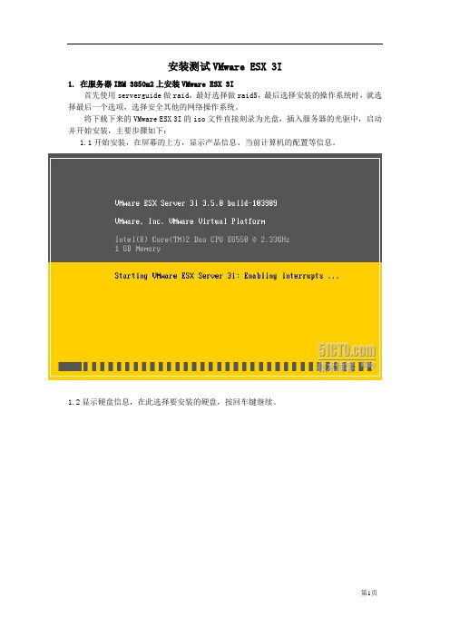
将下载下来的VMware ESX 3I的iso文件直接刻录为光盘,插入服务器的光驱中,启动并开始安装,主要步骤如下:1.1开始安装,在屏幕的上方,显示产品信息、当前计算机的配置等信息。
1.2显示硬盘信息,在此选择要安装的硬盘,按回车键继续。
1.3按F11键开始安装,按ESC退出。
1.4 按F11接受许可协议。
1.5 开始安装,这一步只需要几分钟的时间。
1.6 安装完成后,按回车键重启。
1.7 再次进入系统后,提示管理地址。
(为了安全起见,后面的地址均隐去)1.8 按F2,进入配置界面可以设置root用户口令,如下图所示。
1.9在“Configure Management Network”中可以设置主机名称、IP地址等,在其子菜单中,可以查看网卡MAC地址、设置VLAN、IP地址等,最后设置完毕如图所示。
设置完成后,按ESC返回1.7中界面。
注:(1)要检查网络设置成功没有,回到图1.7界面后,可以再按F2进入图1.8,选择(2)不知道为什么,我按照公司的网络配置来自定义网络配置时,总是ping不通网关,不知是不是因为公司是DHCP模式,我在“Configure Management Network”配置中最后选择自动获取ip地址和DNS,反而可以测试ping通,诡异。
2. 管理ESX 3I返回到主机上,在IE中键入管理端的IP地址https://192.168.*.*(1.7中显示的地址),登录VMware ESX 3I进行管理。
2.1如果是在IE7中,则需要单击“继续浏览此网站”,如下图所示。
2.2 单击“Download VMware infrastructure Client”下载VMware ESX 3I管理工具。

IBM System x3850 M2 服务器用户手册目录1 服务器简介............................................................................................................................................. -2 -微处理器:........................................................................................................................................... - 2 - 存:......................................................................................................................................................... - 2 - 驱动器: ............................................................................................................................................... - 2 - 扩展托架:........................................................................................................................................... - 3 - 扩展槽: ............................................................................................................................................... - 3 - 电源:.................................................................................................................................................... - 3 - 大小:.................................................................................................................................................... - 3 - 集成的功能部件:............................................................................................................................. - 4 - 噪音辐射: .............................................................................................................................................. - 5 - 环境:.................................................................................................................................................... - 5 - 散热量: ................................................................................................................................................... - 5 - 电气输入: .............................................................................................................................................. - 6 - 2 服务器功能组件.................................................................................................................................... - 6 -服务器的主要组件: ........................................................................................................................ - 6 - 服务器控件、接口、指示灯和电源:........................................................................................ - 7 - 开启服务器......................................................................................................................................... - 14 - 关闭服务器......................................................................................................................................... - 15 -1 服务器简介微处理器:·Intel® Xeon™多核MP·每个核心2 MB(最小)二级高速缓存·1066 MHz 前端总线(FSB)·最多支持四个微处理器注:使用Configuration/Setup Utility 程序可确定微处理器的类型和速度。
IBM XServer3650M3安装redhat5 系统摘要IBM XServer服务器,在包装盒子中,都能发现ServerGuide光盘。
不过,最新采购的3650M3机器包装打开后,居然只有两张没什么用处的光盘,一张是document,另一张是director,却没有ServerGuide的踪影。
在IBM官网上下载的for 3650M3的ServerGuide,居然不支持linux系统。
经过反复测试,花了大半天的时间后,终于找到了在其上安装redhat5的方法。
硬件配置型号:IBM X3650M3产品编号(PID):7945165序列号:【略】CPU:X5660 2.8GHz 6.4GT/s 6核12线程内存:2×4G,1333MHz硬盘:4×146G问题问题1:在包装内,未发现ServerGuide光盘;问题2:插入redhat5 64位安装盘,未发现硬盘;问题3:通过使用下载的ServerGuide光盘,在选择安装操作系统的界面,如果选择Win2008,则会在安装redhat5时,提示不能识别gpt分区表。
安装过程由于购买了4块硬盘,为系统的安全考虑,我们选择配置raid10。
一、ServerGuide下载包装内未发现ServerGuide启动盘;直接使用redhat5安装盘,也找不到4快硬盘;即使找到了,也无法配置raid10。
因此,到IBM官网上去尝试下载ServerGuide。
在/support/entry/portal/docdisplay?lndocid=MIGR-5079561发现有支持IBM3650M3的8.31版本的ServerGuide。
下载ibm_utl_sguide_8.31_anyos_x86-64.zip后解压,得到iso刻录文件,并根据提示内容(Note: Burning the ISO image to a DVD is not supported. The ISO image must be burned to a CD to work correctly.)刻录CD盘。
This guide describes the minimum steps you must perform to power on and boot your server for the first time.Detailed installation information can be found in the Sun Fire X4170M2and X4270M2Servers Installation Guide ,which is available at Oracle’s documentation web sites for the individual servers.Refer to the section“Documentation for This Product”at the end of this document for a list of documentation for your system.ContentsOracle’s Sun Fire X4170M2and X4270M2Servers are shipped with safety documentation and the components that you ordered for your configuration.Optional components or rack installation equipment might be packaged and shipped separately.Documentation and Media KitThe Documentation and Media Kit is an orderable option for your system.It contains installationdocumentation,the Tools and Drivers DVD,the Oracle Hardware Installation Assistant CD,and the Oracle Validation Test Suite CD.You can order the Documentation and Media Kit at any time,using the following marketing part number:X5935A.You also can download the documentation and software that are included in the Documentation and Media Kit.■For documentation,go to:■For Sun Fire X4170M2–/pls/topic/lookup?ctx=E19762-01■For Sun Fire X4270M2–/pls/topic/lookup?ctx=E19245-01■For software,go to:■For Sun Fire X4170M2–/goto/x4170m2■For Sun Fire X4270M2–/goto/x4270m2Safety and Compliance InformationBefore performing an installation,refer to the following documents for safety information:■Important Safety Information for Sun Hardware Systems –Printed document included in the ship kit.■Sun Fire X4170M2and X4270M2Servers Safety and Compliance Guide –Online at the documentation web site.Sun Fire X4170 M2 and X4270 M2ServersGetting Started Guide▼Install Optional ComponentsBefore installing the server into the rack,you must first install any optional components that you ordered with the server and that were not factory installed.Refer to the Sun Fire X4170M2Server Service Manual and the Sun Fire X4270M2Server Service Manual for the instructions on installing optional components.▼Mount the System in a RackFor rackmounting instructions,refer to the documents included with the rail kit,the service label on the server,and to the Sun Fire X4170M2and X4270M2Servers Installation Guide .▼Connect the Cables and Apply Standby Power to the Server1.Connect a serial cable between the server’s SER MGT port (FIGURE 1)and a serial terminal device.This connection provides your initial communication with the service processor (SP).The terminal device must be set up to communicate using 9600baud,8bit,no parity,1stop bit.A null modem configuration is needed,meaning the transmit and receive signals are reversed (crossed over)for DTE to DTEcommunications.You can use the supplied RJ-45crossover adapter with a standard RJ-45cable to achieve the null modem configuration.(FIGURE 1shows the Sun Fire X4170M2Server.The locations of the back panel connectors and ports are the same on the Sun Fire X4270M2Server.)FIGURE 1Back Panel of Server (Server Connections)2.(Optional)Connect an Ethernet cable between the server’s NET MGT port and the network to whichfuture connections to the SP will be made.After the initial configuration of the system using the SER MGT port,communication with the SP is usually performed through this Ethernet interface.3.Connect an Ethernet cable between one of the server’s NET ports (NET 0,1,2,or 3)and the network towhich the server will communicate.4.Connect the server power cords to AC power outlets and,to enhance redundancy,to separate powersources.When standby power is applied,the SP initializes and the Power/OK LED flashes in Standby Blink pattern (0.1seconds on,2.9seconds off)(see FIGURE 2and FIGURE 3).Note that the server is not initialized orpowered on yet.For more information on connectivity options,refer to the Sun Fire X4170M2and X4270M2Figure Legend1AC power connectors4Gigabit Ethernet ports NET 0,1,2,3(Intel)2Serial management (SER MGT)/RJ-45serial port 5USB 2.0ports (0,1)3Service processor network management (NET MGT)port6HD15video connector (analogVGA)At this point,standby power is supplied only to the SP and power supply fans.Do not apply main power to the rest of the server until you are ready to install an operating system.In standby power mode,the Power/OK LED flashes in Standby Blink (0.1seconds on,2.9seconds off).FIGURE 2shows the Sun Fire X4170M2Server.FIGURE 3shows the Sun Fire X4270M2Server with twelve 3.5-inch drives;the front panel controls on the Sun Fire X4270M2Server with twenty-four 2.5-inch drives (not shown)support the same functions.FIGURE 2Sun Fire X4170M2Server Front Panel ControlsFIGURE 3Sun Fire X4270M2Server Front Panel ControlsConnecting to Oracle ILOMYou can start,boot,and manage the server using the Oracle Integrated Lights Out Manager (Oracle ILOM)software that runs on the server’s SP.There are two methods for connecting to Oracle ILOM:■Connect to Oracle ILOM using a serial connection (SER MGT port)See “Connect to Oracle ILOM Using a Serial Connection”for instructions.■Connect to Oracle ILOM using an Ethernet connection (NET MGT port)See the Sun Fire X4170M2and X4270M2Servers Installation Guide for instructions.To connect via an Ethernet connection,you must know the IP address of the server SP.In a typical configuration,you will accept the IP address assigned by the DHCP server or IPv6router.If you are not using DHCP or an IPv6router,or if you need to assign the server SP a static IP address for any other reason,refer to the Oracle Integrated Lights Out Manager (ILOM)3.0Documentation Library for instructions.Figure Legend1Power/OK LED 2Power ButtonFigure Legend1Power Button 2Power/OKLED▼Connect to Oracle ILOM Using a Serial Connection1.Connect a terminal device to the server.See Step1in“Connect the Cables and Apply Standby Power to the Server”.2.Press Enter on the terminal device to create a connection between the terminal device and the OracleILOM SP.The Oracle ILOM login prompt appears.3.Log in to the Oracle ILOM CLI using the root user account and the root password,changeme.The Oracle ILOM CLI prompt appears(->).You can now start,configure,and manage the server using Oracle ILOM.▼Apply Main Power to the ServerCaution–Do not operate the server without all fans,component heatsinks,air baffles,and the cover installed.Severe damage to server components can occur if the server is operated without adequatecooling mechanisms.1.Verify that the power cords have been connected(FIGURE1)and that standby power is on.2.Press and release the recessed Power button on the front panel(FIGURE2and FIGURE3).When main power is applied to the full server,the Power/OK LED lights and blinks while BIOS initializes.The Power/OK LED lights steady green when the system is loading an OS.3.Continue with initial software setup tasks,as described in the Sun Fire X4170M2and X4270M2ServersInstallation Guide.▼Upgrade FirmwareIt is highly recommended that you use the Oracle Hardware Installation Assistant to upgrade system BIOS and Oracle Integrated Lights Out Manager(Oracle ILOM)firmware.The Oracle Hardware Installation Assistant is easy to use and available in the Documentation and Media Kit,or online at:For more information,refer to the documentation for the version of Oracle Hardware Installation Assistant supported for your server at:/pls/topic/lookup?ctx=hiaFor instructions on upgrading system BIOS and Oracle ILOM firmware without using Oracle Hardware Installation Assistant,go to the Oracle ILOM3.0Documentation Library at:/pls/topic/lookup?ctx=ilom30All firmware and drivers are located on the Tools and Drivers DVD,which is part of the Documentation and Media Kit.You also can download the software on the Tools and Drivers DVD from the Oracle software download sites(see links in the following table).▼Set Up the Platform Operating System and Driver SoftwareYou can configure the preinstalled or supported operating system(OS)for your server.The following table provides additional references for installing an operating system,system device drivers,firmware,and patches.At the product web site (/goto/x4170m2or/goto/x4270m2),use the links to navigate to the information you need.▼For Technical SupportFor techincal support,see /us/corporate/contact/index.htmlFor information on a software service plan,see /support/premier/index.html If you need service for your system,you might be asked for your hardware serial number.To find the serial number of your system,use the Oracle ILOM command show /SYS ,or see your Installation Guide or Service Manual for information about where to find the serial number label for your system.Operating system:Read the Sun Fire X4170M2and X4270M2document:For installation information,go to:For latest tools,drivers,firmware,and the OracleHardware Installation Assistant,go to:For patch information,go to:Preinstalled Oracle Solaris or Oracle VMInstallation Guide•http:///goto/x4170m2•http:///goto/x4270m2•http://support.orac •See the Sun Fire X4170M2and X4270M2Servers Product Notes •http://Oracle SolarisInstallation Guide for Linux,Virtual Machine Software,and OracleSolaris Operating Systems•http:///goto/x4170m2•http:///goto/x4270m2Virtual Machine Software•http:///virtualization/•http:///•http:///virtualization/•http://downloads.vmware .com/Windows•Windows or Linux:Oracle Hardware Installation Assistant 2.5Users Guide for x86Servers•Windows:Installation Guide for Windows Operating Systems •Linux:Installation Guide for Linux,Virtual Machine Software,and Oracle SolarisOperating Systems•http:// •http:///goto/x4170m2•http:///goto/x4270m2Windows or Linux:Use the Oracle Hardware Installation Assistant for automaticfirmware update and driver installationhttp://update.microsoft .com/Linux•Red Hat:https:///apps/download/•SUSE:http://download.novell .com/index.jspDocumentation for This ProductThe following table lists the documentation and the approximate order of tasks that you might perform when installing a system.For the most up-to-date English and translated versions of some of the documents,go to the Oracle documentation site■For Sun Fire X4170M2–/pls/topic/lookup?ctx=E19762-01■For Sun Fire X4270M2–/pls/topic/lookup?ctx=E19245-01Task DocumentReview safety information.Sun Fire X4170M2and X4270M2Servers Safety andCompliance GuideImportant Safety Information for Sun Hardware Systems Review known issues and workarounds.Sun Fire X4170M2and X4270M2Servers ProductNotesInstall rack hardware.Cable and power on server.Connect to service processor.Configure preinstalled Oracle Solaris OS.Sun Fire X4170M2and X4270M2Servers Installation GuideInstall and configure the Oracle Solaris,Linux,Windows OS,or install virtual machine software such as Oracle VM or VMware.Sun Fire X4170M2and X4270M2Servers Installation Guide for Linux,Virtual Machine software,and Oracle Solaris Operating SystemsSun Fire X4170M2and X4270M2Servers Installation Guide for Windows Operating SystemsOracle Hardware Installation Assistant2.5Users Guide for x86ServersManage server accounts,monitor alerts,set remote access andredirection,and view component status and event logs.Oracle ILOM3.0DocumentationCustomize BIOS settings and RAID settings.Remove and replace hardware components.Troubleshoot and isolate server problems.•Sun Fire X4170M2Server Service Manual •Sun Fire X4270M2Server Service ManualDiagnose system issues.Sun x64Servers Diagnostics GuideCopyright©2010,2011,2012Oracle and/or its affiliates.Copyright©2010,2011,2012Oracle et/ou ses affiliés.Part No. E27118-02, Rev. AJanuary 2012。
蓝色基因 IBM X3650 机架式服务器评测IBM 服务器以 System i 、 P、 X、 Z 四大系列服务器产品线为主,在x86 市场中 System x 系列服务器则是最受用户关注的产品,System x 服务器系列产品鉴于英特尔至强办理器及AMD皓龙办理器产品,面向单路、双路和多路产品等服务器,能够知足中小型公司用户的需求。
本次评测我们收到的服务器是 IBM System x3650 服务器,这是一款鉴于英特尔 45 纳米至强办理器的 2U 服务器,在 x86 市场中是绝对主力机型,依靠优秀的售后服务和软件支持获取了广大用户的认同。
IBM X3650 服务器外观介绍:IBM X3650 服务器外观作为一款 2U 经典的双路服务器,IBM X3650 持续了 System x 系列的经典外观设计,黑色的前方板给人一种沉着、大气的感觉,彰显IBM 不俗的产品气质。
我们本次收到的IBM X3650 服务器标配了两颗45 纳米 Xeon 5405 办理器,拥有 12MB二级缓存,前端总线达到了 1333MHz。
4 根 1GBDRRIISDRAM(Chipkill) 内存,两块 15K 146GB 硬盘构成 RAID 0 模式。
六个 3.5 英寸热插拔硬盘位IBM X3650 服务器供给了六块 3.5 英寸热插拔硬盘位,最大储存容量能够支持 1.8TB SAS或 6.0TB SATA即牢固又为硬盘协助散热。
热插拔硬盘。
在上边的图中我们能够看到热插拔硬盘支架采纳了铝合金制作,在硬盘架的面板上还有 EMI 弹片,增强了服务器的障蔽能力。
前方板独到的蜂窝式散热风格,为服务器带来了更大的进风量,“System x3650”的字样标明在面板中间偏左的地点,特别醒目。
在左边的面板上我们挨次看到信息面板,包含(由左到右)电源开关、供电指USB 示灯、硬盘活动指示灯、系统定位指示灯、信息指示灯和系统错误指示灯。
目录第1章产品介绍 (1)1.1服务器 (1)1.2引导工具 (2)第2章光盘刻录 (7)2.1 引导盘刻录 (7)2.2 安装盘刻录 (8)第3章Raid卡配置 (9)第4章添加USB引导 (15)第5章系统安装 (19)第1章产品介绍1.1服务器IBM System x3650 M1、M2、M3、M4是IBM公司的产品,Lenovo收购后,推出了Lenovo System x3650 M5。
M5相关介绍:/abstracts/tips1193.html?Open#osM5支持的操作系统如下:M5相关图片如下:1.2引导工具引导工具在Lenovo收购前后有所区别。
收购前,比如ServerGuide9.41版本,命名ibm_utl_sguide_9.41-win2k03-08_anyos_x86-64.iso;从该地址的介绍中知,该工具支持的Lenovo 产品如下:该工具支持的IBM产品如下:第2章光盘刻录整个安装过程使用DVD+DVD,或者U盘+DVD的模式,分别用来刻录引导盘、操作系统。
引导盘可以使用DVD或者U盘刻录,安装盘经过测试不能使用U盘,必须使用DVD刻录。
本教程使用U盘+DVD的形式。
2.1 引导盘刻录先下载所需的工具,有两个版本,分别支持Windows Server2008和Windows Server 2012,根据需要进行下载,下载地址:https:///support/entry/portal/docdisplay?lndocid=LNVO-GUIDE下载后,安装引导盘制作工具UltraISO,打开工具,刻录过程可参考如下百度经验/article/11c17a2c717e6cf446e39df8.html。
根据光驱的速度,整个过程可能需要3-8分钟。
值得注意的是,如果使用U盘制作引导盘,制作时有一点区别,应选择写入硬盘映像,如下图。
2.2 安装盘刻录安装盘刻录同引导盘刻录基本相同,可参考百度经验:/article/4ae03de34c61bb3efe9e6b45.html 根据光驱的速度不同,整个过程可能需要5-15分钟。
System x 3850M2 (Types 7141/7233) RHEL5U1安装指南
一.安装前的准备
1.1 安装前需要准备什么:
检查并升级主板BIOS/BMC到最新版本
一套有许可证的Red Hat Enterprise Linux 5 Update 1的光盘(DVD或CD)
该服务器支持的硬盘驱动器,查看Serverproven链接列表,以获取该服务器支持的硬盘型号信息。
Serverproven链接:/servers/eserver/serverproven/compat/us/
注:如果没有光驱,或者确定要采用网络安装等方式,请参考Red Hat官方安装文档。
本文档仅介绍采用光驱本地安装的大致参考步骤。
1.2 从哪儿获取驱动程序:
该型号服务器驱动程序下载列表:
/systems/support/supportsite.wss/selectproduct?family ind=5357828&typeind=0&osind=0&brandind=5000008&taskind=2&matrix=Y&psid=sp&conti nue.x=14&continue.y=15
IBM System x服务器技术支持网站:
/systems/support/supportsite.wss/brandmain?brandind=5 000008&ui=gc
二.操作系统安装
2.1必要的设置:
1. 启动服务器,开机自检有“press F1 for setup”提示时,按下“F1”键。
2. 选择“Load default settings”选项,把BIOS设置恢复默认设置。
3. 选择“Advanced Settup”,然后选择“RSA II Settings”。
4. 按下方向键,选择“OS USB Selection”,用左右方向键更改该选项的值为“Linux”。
5. 按下方向键,选择“Save Values and Reboot RSA II”。
6. 按“Enter”键,保存更改过的设置,并且重启RSA II。
7. 返回到主菜单。
8. 选择“Save Settings”保存更改过的设置。
9. 退出BIOS设置界面,并且重启服务器。
2.2操作系统安装:
1. 启动服务器,将“Red Hat Enterprise Linux 5 Update 1”DVD光盘或CD1光盘放入光盘驱动器,用光盘引导启动。
启动到如图示的“Boot:”提示位置时,根据实际需要选择安装方式。
(本例中采用图形安装方式,因此直接按下Enter键即可。
)
2. 加载文件后,提示发现光盘介质,是否需要进行媒体介质检测。
确定时候要检测媒体介质后,继续进行。
(本例中选择Skip跳过检测步骤。
)
3. 安装程序进入到图形安装界面,可以查看发行说明等,点击“Next”继续。
4. 根据实际情形,选择语言类型,然后点击“Next”继续。
(本例采用默认设置。
)
5. 根据实际需求选择键盘布局后,点击“Next”继续。
(本例采用默认设置。
)
6. 输入Red Hat Enterprise Linux 5 update 1的安装序列号,点击“OK”继续。
7. 根据实际环境需求,选择硬盘分区方式。
共有“Remove all partitions on selected drives and create default layout”,“Remove Linux partitions on selected drives and create default layout”,“Use free space on selected drives and create default layout”和“Create Custom layout”四种方式。
如果实际有非常严格的分区规则,通常会选择“Create Custom layout”自定义分区的方式。
(本例采用“Remove all partitions on selected drives and create default layout”删除所选硬盘上所有分区并创建默认分区的方式。
)
注:即使选择前三种默认方式,也可以通过勾选“Review and modify partitioning layout”选
项来修改具体的分区信息。
8. 提示分区会造成硬盘上原有数据丢失,确认后,点击“Y es”继续。
9. 勾选“Review and modify partitioning layout”选项之后,会进入默认分区信息的纵览界面,该界面可以对分区进行调整或完全重新定制(与“Create Custom layout”方式相似。
)。
确认后点击“Next”继续。
注:步骤7中,如果不选择“Review and modify partitioning layout”选项,则不会有该步骤,直接进入步骤10画面。
10. 设置boot loader,完成后点击“Next”继续。
11. 设置网络参数,完成后点击“Next”继续。
12. 设置时区以及是否使用UTC等,完成后点击“Next”继续。
13. 设置Root用户密码,完成后点击“Next”继续。
选项。
)
注:由于一般服务器安装完成后,可能需要安装其他诸如网卡,HBA卡能设备驱动程序或其他应用程序,通常建议勾选Development软件包组下的Development Libraries和Development Tools两个软件包组。
自定义软件包后,点击“Next”继续。
15. 最终确认安装配置后,点击“Next”开始安装。
16. 安装过程结束后,点击“Reboot”按钮重启服务器。
17. 重启服务器之后,根据实际环境需求进行相应配置。
三.安装设备驱动
集成网卡驱动程序安装说明及下载地址:
/systems/support/supportsite.wss/docdisplay?lndocid=MIGR-5081937& brandind=5000008
四.参考资料
https:///docs/manuals/enterprise/#RHEL5。