Kvaser Leaf Install Guide
- 格式:pdf
- 大小:834.12 KB
- 文档页数:17
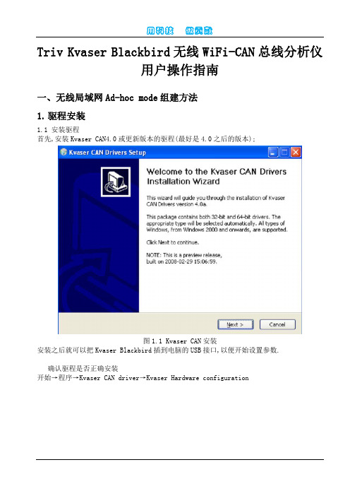
Triv Kvaser Blackbird无线WiFi-CAN总线分析仪用户操作指南一、无线局域网Ad-hoc mode组建方法1.驱程安装1.1 安装驱程首先,安装Kvaser CAN4.0或更新版本的驱程(最好是4.0之后的版本);图1.1 Kvaser CAN安装安装之后就可以把Kvaser Blackbird插到电脑的USB接口,以便开始设置参数.确认驱程是否正确安装开始→程序→Kvaser CAN driver→Kvaser Hardware configuration图1.2 Kvaser Hardware Configuration启动图1.3若能像在图1.3中能见到Kvaser Blackbird就表示驱程已经正确安装.2、 WINDOWS的相关设置2.1无线局域网的启动设置开始→管理工具→服务 →左键点击,选择Wireless Zero Configuration(如图2.1所示)图2.1 无线支持启动在弹出的菜单中,选择启动.启动完毕后,可以关闭该窗口.如图2.2图2.2 启动无线支持2.2 打开网络连接的窗口,右键点击无线网络连接再选择属性,弹出如图2.3窗口.图2.3选中”用windows配置我的无线网络设置”.如果首选网络中为空,则点击”添加”.弹出如图2.4的窗口,按照图所示设置,需要注意的是网络名(SSID)要与本地计算机的无线网络名一致.图2.42.3 若在图2.3中没有出现“无线网络配置”一栏,则是由于系统版本问题,此时应该装相应的服务包:(1)Windows XP的操作系统必须先安装 Windows XP Service Pack 2 和 WPA2/WPS IE Update 或者 Windows XP Service Pack 1 和 Wireless Update Rollup Package.(2)而对于Windows 2000操作系统,必须安装 Service Pack 4 或者更新版本来支持无线连接.3、ad-hoc模式网络设置3.1在ad-hoc模式下,首先要通过计算机设置blackbird的相关参数.可以直接将Blackbird 与电脑通过USB连接在一起,因此必须给Blackbird和电脑都分配IP地址.地址分配如下图3.1:图3.13.1.1控制面板→网络连接→右键点击“无线网络连接” →属性→双击“Internet协议(TCP/IP)”。
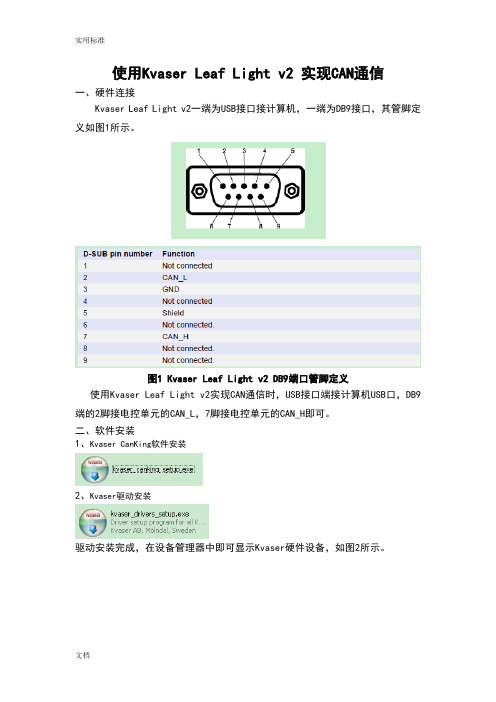
使用Kvaser Leaf Light v2 实现CAN通信一、硬件连接Kvaser Leaf Light v2一端为USB接口接计算机,一端为DB9接口,其管脚定义如图1所示。
图1 Kvaser Leaf Light v2 DB9端口管脚定义使用Kvaser Leaf Light v2实现CAN通信时,USB接口端接计算机USB口,DB9端的2脚接电控单元的CAN_L,7脚接电控单元的CAN_H即可。
二、软件安装1、Kvaser CanKing软件安装2、Kvaser驱动安装驱动安装完成,在设备管理器中即可显示Kvaser硬件设备,如图2所示。
图2 CAN Hardware(Kvaser)硬件连接成功三、Kvaser CanKing软件使用步骤1、点击电脑的“开始”选择“所有程序”里面的Kvaser CanKing,即可进入CanKing 软件,见图3:图3 Kvaser CanKing打开点击CanKing软件,弹出警告对话框,如图4所示。
图4 Kvaser CanKing打开弹出警告对话框选择OK,弹出Kvaser CanKing工程选择对话框,见图5:图5 Kvaser CanKing工程选择对话框2、选择OK,弹出Template对话框,可以选择支持单通道的测试仪或者双通道的测试仪,见图6,因为本说明中使用的是Kvaser USBcan Ⅱ,因此选择CAN kingdom(2 channels)。
图6 Template对话框3、选择OK进入到Kvaser CanKing软件界面,见图7:图7 Kvaser CanKing软件界面在CAN1设置框中的“Bus Parameters”栏中设置波特率250000bit/s,选择应用即可,如图8所示。
图8 Kvaser CanKing软件CAN1参数设置界面4、设置发送数据帧显示格式,选择Kvaser CanKing菜单栏的Options→Global,见图9所示。
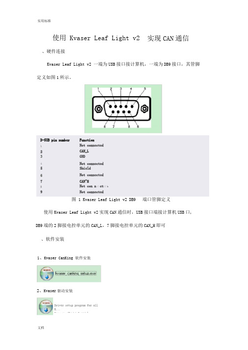
使用 Kvaser Leaf Light v2实现CAN通信、硬件连接Kvaser Leaf Light v2 一端为USB接口接计算机,一端为DB9接口,其管脚定义如图1所示。
D-5UB pin number FunctionNot connected12 CAN_L3GND4Not connected5 Shield6Not connected7 CAN^HS Not con n亡ct亡b9 Not connected图 1 Kvaser Leaf Light v2 DB9 端口管脚定义使用Kvaser Leaf Light v2实现CAN通信时,USB接口端接计算机USB口, DB9端的2脚接电控单元的CAN_L,7脚接电控单元的CAN_H即可、软件安装1、Kvaser CanKing 软件安装2、Kvaser驱动安装Driver setup program for allK...Kvas er ABj h4ofc-idal驱动安装完成,在设备管理器中即可显示Kvaser硬件设备,如图2所示文件⑹操住⑹查若⑹帮■肋t也舸3!-PC-201.20412095jh£4 Kvaser Leaf Light 吨砂Kvaser Network. EnumeratorKvas&r Wtud CAN Driver图2 CAN Hardware(Kvaser) 硬件连接成功、Kvaser CanKing软件使用步骤1、点击电脑的“开始”选择“所有程序”里面的Kvaser CanKing,即可进入Can Ki ng软件,见图3:图 3 Kvaser Ca nKing 打开点击CanKing软件,弹出警告对话框,如图4所示图4 Kvaser Can Ki ng 打开弹出警告对话框选择OK,弹出Kvaser CanKing工程选择对话框,见图5:图5 Kvaser Can Ki ng 工程选择对话框2、选择0K,弹出Template对话框,可以选择支持单通道的测试仪或者双通道的测试仪,见图6,因为本说明中使用的是Kvaser USBcan U,因此选择CAN kingdom (2 channels )。
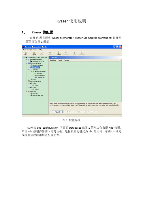
Kvaser使用说明1、Kvaser的配置在开始-所有程序-Kvaser Memorator- Kvaser Memorator professional打开配置界面如图1所示图1 配置界面(1)双击Log configuration 下面的Databases在图1的左边会出现Add按钮,单击add按钮弹出图2的对话框,选择相应的格式为.dbc的文件,单击OK则完成将通信程序添加进配置文件。
图2 选择database对话框(2)双击Bus configuration 下的CAN1得图3所示界面在Bitrate and sampling point(如图中红色所圈位置)一栏填写通信所用波特率。
图3 CAN通道配置注:CAN2与CAN1的配置方式相同,配置好后可以将配置文件保存。
(3)将kvaser与电脑连上点击配置界面上的Connect弹出如图4所示界面,单击Next弹出图5所示界面,单击finish则完成kvaser设备的连接。
图4 选择设备图5 准备连接(4)设备连接后图6中红色圈圈部分被激活,点击download弹出图7所示对话框,单击Ok在图8所示的红圈中显示configration successfully downloaded,说明上文所描述的配置以及下载到仪器了。
配置好的kvaser则可以用来记录数据。
图6 配置界面图7 配置下载到设备图8 配置成功2、Kvaser的现场使用Kvaser有两个通道,Ch.1和Ch.2这两个通道都是9针的公头,两个通道的7针为CAN高,2针为CAN低,其中Ch.1的5针为24V+、3针为地(千万不要接反了)。
当电源接好后仪器上的PWR灯会一闪一闪的,当Ch.1和Ch.2的任何一个通道使用时相应的灯会亮(Ch.1对应CANⅠ;Ch.2对应CAN Ⅱ)说明通信正常。
当ERR灯亮时说明出现通信错误,或者帧丢失。
3、Kvaser记录的数据的导出(1)按上文所说的方式将仪器与Kvaser Memorator professional进行连接单击Flesh disk 下的Log files则出现图9所示界面第一步:单击List files 界面中出现记录的数据,选中需要导出的文件。

Kvaser Database Editor User’s GuideVersion 2.0Copyright 2001-2003 KVASER AB, Mölndal, SwedenLast updated Monday, 24 January 2011 - Printed Monday, 24 January 2011(This page is intentionally left blank.)1 Table of Contents1Databases (4)1.1Overview (4)1.2Database Editor (4)1.2.1The main menu (5)1.2.2The toolbar (5)1.2.3The Tree View (6)1.2.4The Message View (7)1.2.5The Layout View (8)1.2.6The Signal View (8)1.2.7The Node List View (9)1.2.8The Communication Matrix View (9)1.2.9The Environment Variables View (10)1.3Glossary (11)1.4Support (11)2Document revision history (12)2 Databases2.1 OverviewTo edit or create a database, use the Database Editor. You can start the editor from the Kvaser program group in the start menu.2.2 Database Editor1 2 3Figure 1 The Database EditorThe Database Editor main window consists of the following parts:1. The main menu2. The toolbar3. Tabs for switching between∙The Message/Signal View∙The Node List∙The Communication Matrix.∙The Environment Variables View4. The Tree View.5. The Message View.6. The Layout View.7. The Signal View.2.2.1 The main menuThe main menu consists of two pull-down menus: File and Help.2.2.1.1 The File menuThe File menu consists of following functions:∙New - With this function you create a new clean database. This function is also available by pressing Ctrl+N on the keyboard or pressing the New button in the toolbar.∙Open - With this function you open an existing database. This function is also available by pressing Ctrl+O on the keyboard or pressing the Open button in the toolbar.∙Append– With this function you append one database to another.∙Save - With this function you save your database in the current working directory. This function is also available by pressing Ctrl+S on the keyboard or pressing the Save button in the toolbar.∙Save As - With this function you save your database in the current working directory witha new name.∙Exit - With this function you exit the Database Editor.2.2.1.2 The Help menuThe Help menu consists of the following functions:∙Kvaser Database Editor Help - Click here to access the database editor help pages.∙About - Click here to access the About Box. Useful for determining which version of the Database Editor you are running.2.2.2 The toolbarFigure 2: The toolbarThe toolbar consists of the following items:1. Toolbar detach button - Click here if you want to detach the toolbar from the window.2. New - With this function you create a new clean database. This function is also availableby pressing Ctrl+N on the keyboard or clicking File | New in the main menu.3. Open - With this function you open an existing database. This function is also availableby pressing Ctrl+O on the keyboard or clicking File | Open in the main menu.4. Save - With this function you save your database in the current working directory. Thisfunction is also available by pressing Ctrl+S on the keyboard or clicking File | Save in the main menu.5. Delete Messages button - Click here to delete the selected messages from the database.6. Insert Message button – Click here to insert a new message into the database.7. Delete Signals button - Click here to delete the selected signals from the database.8. Insert Signal button –Click here to insert a new signal into the currently selectedmessage.9. Find field – Type a text string to search for among message names and signal names inthe database. The search function is not case sensitive. Click the Search Down button to perform the search.10. Search Down button – Click here to search the database. The text to search for must betyped into the Find field positioned to the left in the toolbar.11. Expand Signal button – Click here to expand the length of the currently selected signalby one bit.12. Shrink Signal button - Click here to shorten the length of the currently selected signal byone bit.13. Move Signal Up button –Click here to move the signal inside the message one bitposition up.14. Move Signal Down button - Click here to move the signal inside the message one bitposition down.2.2.3 The Tree ViewIn the Tree View you can see the current database in a tree structure. The database expands to CAN messages, environment variables and nodes. The CAN messages expand in turn to signals.Figure 3 The Tree ViewClicking the right mouse button will open a submenu with insert and/or delete items. The contents of this submenu vary based on the tree structure level you have highlighted.At the database level (root), you will only have Database Overview and Line Up in the submenu. The Database Overview submenu item will hide the tree view and you will se the message/signal view over the whole window. To view the tree view again, right click on the menu bar area (beside File, Tools and Help).In the tree view it is possible to insert new messages, signals and environment variables to your database. To insert a new message into the database right click on CAN messages in the tree view and click on the submenu item insert Message. This function is also available by pressing the Insert Message button on the toolbar. To insert environment variable or node do the same as for insert message.At the message level you will have the following two items in the submenu:∙Delete Message - Click here to delete the currently selected message. This function is also available by pressing the Delete Message button on the toolbar.∙Insert Signal - Click here to insert a new signal into the currently selected message. This function is also available by pressing the Insert Signal button on the toolbar.At the signal level, you will only have the Delete Signal item in the submenu. This item deletes the currently selected signal. This function is also available by pressing the Delete Signal button on the toolbar.2.2.4 The Message ViewFigure 4 The Message ViewIn this view each message is presented. If you have created a new message you can set its parameters here. The information in the following columns defines the message:∙Message Name - Type the desired na me. A new message will be named ‘NewMessage’ by default.∙CAN Identifier - Set up a CAN Identifier for the message. Default Id is 0.∙Identifier Type- Select Standard or Extended from a dropdown list. Default type is Standard.∙DLC - Select the data length code from a dropdown list. Default DLC is 0.∙Sending Node - Select a node from dropdown list. Nodes are defined in Node View.∙Comment– Enter a message description.Figure 5: The Layout ViewIn this view you can see how the bits for each byte in the message are occupied by signals. As you insert signals, the bits used by the signals will be marked in this view with different colors for each signal.2.2.6 The Signal ViewFigure 6 The Signal ViewIn this view, each signal in the selected message is displayed. If you have created a new signal, you can set its parameters here. The information in the following columns defines the signal:∙Signal Name- Type the desired name. A new signal will be named ‘NewSignal’ by default.∙Type- Set up the data type of the signal. Alternatives are Signed, Unsigned, Float or Double.∙Format- Select a format from the dropdown list. Alternatives are Intel or Motorola.Default is Intel.∙Mode - Select a mode from the dropdown list. Alternatives are Normal or Mode Signal.Default is Normal.∙Startbit - Select the start position of the signal in the message. Default is 0.∙Length - Select the length of the signal in bits. Default is 0.∙Factor– Enter a scaling factor if one is used. Default is 1.∙Offset– Enter an offset if used. Default is 0.∙Minimum - Enter the minimum possible signal value. Default is 0.∙Maximum - Enter the maximum possible signal value. Default is 0.∙Unit - Enter the unit the signal is represented in. No default.∙Comment - Enter a description of the signal.∙Values – Enter an alias for a signal value.Figure 7 The Node List ViewIn this view, the defined nodes in the database are displayed. This is where you insert and delete nodes. Clicking the right mouse button Opens a submenu with the following items:∙Delete Node - Click here to delete the currently selected node.∙Insert Node - Click here to insert a node into the database.The view consists of following columns:∙Node Name - Type the desired name. A new Node will be named ‘NewNode’ by default.∙Comment - Enter a description of the node.When a node is created, the node will appear as a selectable item in the dropdown list in the Sending Node column of the Message view.2.2.8 The Communication Matrix ViewFigure 8 The Communication Matrix ViewThe Communication Matrix can be used to associate Network Nodes with Signals. To do this, double-click in the Signal's row and Node's column.2.2.9 The Environment Variables ViewFigure 9 The Environment Variables View∙Environment Variable - The name of the Environment Variable.∙Type - The data type of the Environment variable.∙Unit - The Unit of the Environment Variable.∙Min - The minimum value the Environment Variable can have.∙Max - The maximum value the Environment Variable can have.∙Start Value - The start value of the Environment Variable.∙Comment - An optional comment.∙Access - The type of access of the Environment Variable (read/write/unrestricted).∙Values - An Environment Variables can tie a number of symbolic values to it. These are specified here.2.3 GlossaryBit time The time one single bit occupies when sent on the CAN bus. A bit time is composed of three parts: tsync (1 time quantum), tseg1 (2 – 16 time quanta)and tseg2 (1 – 8 time quanta). A bit time occupies 4 – 25 time quanta.Extended CAN The same as CAN 2.0B. Message identifiers are 29 bits long.Prescaler Factor used to scale time quanta from oscillator (usually 16 MHz).Sampling point Position where a bit is sampled expressed from the start of a bit as a percentage of the total bit time. Sample point occurs between tseg1 andtseg2. Sample point = (tsync + tseg1) / (tsync + tseg1 + tseg2).SJW Synchronization Jump Width. Defines the maximum synch compensation allowed in one step. Allowed values are 1 – 4 time quanta. High SJW allows awide oscillator tolerance range. This parameter must be the same for allnodes in the system.Standard CAN The same as CAN 2.0A. Message identifiers are 11 bits long.Time quantum A bit time is conceptually divided into a number of time quanta (typically 8 –25).Tseg1Length (in time quanta) of the time segment between tsync and the sample point. Part of a bit time. 2..16 time quanta.Tseg2Length (in time quanta) of the time segment following the sample point. Part of a bit time. 1..8 time quanta.Tsync Length (in time quanta) of the time segment preceding tseg1. Bit time starts with tsync. It is used to synchronize nodes on the CAN bus. An edge isexpected within tsync. Tsync is always one time quantum long.Working area The working area of the main window shows the actual workspace. The working area is always visible and is the place where you work with yourwindows.Workspace A workspace is used to group windows that you think have something in common. The active workspace is viewed in the working area. To change theactive workspace, click the tabs positioned between the toolbar and theworking area of the main window.2.4 SupportYou can obtain support on a time-available basis by sending an email to support@. Please contact us for information on our other support options.Software updates, bug fixes, and so on will be made available on our web site, .Your opinions are appreciated. Suggestions and bug reports may be sent by e-mail to support@ - if you require a reply, please contact us for more information about our support packages.3 Document revision history。

C4411 Remote Display Installation Guide Type 1 and 12 ApplicationsStep 1 — Enclosure PreparationFor Flat Surface mounting in a Type 1, Type 3R, or Type 12 enclosure, drill or punch two 30mm pilot device holes on 1.75-inch centers a minimum of 1.60 inches (40.6 mm) from every door gasket.Step 2 — Mounting the Remote Display• Insert remote display through the door andadd two gaskets provided behind the door (see Figure 2).• Orient strain relief bracket with respect to your chosen cable routing.•Add two jam nuts provided and tighten 30mm pilot device tool (E22CW recommended) until the strain relief bracket is fl ush with the enclosure door, tighten an additional 1/2 of a turn.Step 3 — Connecting the Remote Display •Select cable up to 10 feet long from Table 1 below and route cable to Motor Insight™, installing communications fi lter provided with C4411 following the instructions in Figure 3.C4411 is Suitable forFlat Enclosures only.TABLE 1.CATALOG LENGHT LENGHT NUMBER INCHES METER D77E-QPIP25 9.8 0.25D77E-QPIP100 39.4 1.0D77E-QPIP200 78.72.0D77E-QPIP300 118.13.0•Secure cable to the strain relief bracket using any suitable tie wrap.Locate the common mode communication fi lter. Open the shell and insert (1) complete loop. Close and snap the shell shut. See Figure 3. The fi lter is to be located asclose to the Motor Insight overload relay as possible.NOTE:The ferrite bead shown above is only required for C441 base units with date codes before 10/1/13.Eaton CorporationElectrical Sector1000 Cherrington Parkway Moon Township, PA 15108 United States877-ETN-CARE (877-386-2273)© 2008 Eaton CorporationAll Rights Reserved Publication No. IL04209003E August 2013 Rev.004PowerChain Management is a registered trademark of Eaton Corporation.All other trademarks are property of their respective owners.Instructional Leafl et IL04209003E Effective August 2013C4411 Remote Display Installation GuideType 1 and 12 ApplicationsT yp e 1/12 R e mot e Display Conv e rsion to 3R Applications For 3R applications, install 3R kit C4413 as follows:1. Loosen the captive screw in C4413 enclosure assembly and removecover.2. Insert User Interface into the base of the 3R enclosure providedand through the holes as prepared in Step 1 above for Type 1/12 installations (Figure 4).3. Follow Steps 2 and 3 from Type 1/12 installation instructions above.4. Insert cover into cam slots Figure 5 and pull cover forward and down,(Figure 6) torque screw 12-15 in-lbNote: Provisions are made for two 3/8” shackle locks to prevent tamperingfrom unauthorized personnel.。
KvaserLeafLight_现场总线分析仪KvaerLeafLight_现场总线分析仪,是一个用于CAN的单通道USB接口。
它能够很容易地把几个接口连接到标准的PC机。
KvaerLeafLight_KvaerLeafLight是一个用于CAN的单通道USB接口。
它能够很容易地把几个接口连接到标准的PC机。
应用范围:KvaerLeafLightCAN总线多用于工控和汽车领域,在CAN总线的开发测试阶段,需要对其拓扑结构,节点功能,网路整合等进行开发测试,需要虚拟、半虚拟、全实物仿真测试平台,并且必须测试各节点是否符合ISO11898中规定的错误响应机制等,所以CAN总线的开发需要专业的开发测试工具,并且在生产阶段也需要一批简单易用的生产线测试工具。
CAN总线开发测试工具的主要供应商有ZLG、PaionI某某AT、IHR、Vector、Intrepidc、PaionWarwick等。
常用的开发测试工具如CANScope、CANalyt-II、PaiontechDiagRA、canAnalyer、某-Analyer、AutoCAN、CANpider等。
应用案例:KvaerLeafLightCAN总线在工控领域主要使用低速-容错CAN即ISO11898-3标准,在汽车领域使用125Kbp的高速CAN。
某进口车型拥有,车身、舒适、多媒体等多个控制网络,其中车身控制使用CAN网络,舒适使用LIN网络,多媒体使用MOST网络,以CAN网为主网,控制发动机、变速箱、ABS等车身安全模块,并将转速、车速、油温等共享至全车,实现汽车智能化控制,如高速时自动锁闭车门,安全气囊弹出时,自动开启车门等功能。
CAN系统又分为高速和低速,高速CAN系统采用硬线是动力型,速度:500kbp,控制ECU、ABS等;低速CAN是舒适型,速度:125Kbp,主要控制仪表、防盗等。
主要特点:◆CAN讯息打上具有100微秒精度的时间-印记KvaerLeafLight_现场总线分析仪,是一个用于CAN的单通道USB接口。
Sigma Install GuidesContentsSigma Partitioning Pages 3-10 Sigma King 0 Pages 11-16 Sigma King 1 Pages 17-22 SSS Handle Pages 23Sigma PartitionYou will need:Drill with hammer action Metal ShearsMole Grips or PliersPop Rivet GunTry Square HacksawSpirit Level Hammer Adjustable Spanner FileTape MeasureScrewdriverAlso: Tek Screw holder, Sockets, Drill Bit Set, Metric Tap Set, Chalk Line, Allen KeysFloor Channel to Floor Hammer Fixing Reverse Side of PartitionMullion to FloorCountersunk Expansion BoltsPanel to PanelM6 x 12 Hex Bolts M6 Hex NutsPanels to MullionM6 x 60 Hex BoltsM6 NutsFloor Channel to FloorHammer FixingCircular Corner Posts M6 x 12 Mushead Bolts 5X25 Tek Screw with Fixed WasherRev B 17/02/17 Overpanel to Panel M6 x 12 Hex Bolts Hex NutsFrame to Floor Hammer FixingsFrame to PanelM6 x 12 Hex BoltsHex NutsPlease note: The threshold strip is a disposable part and should be removed BEFORE installation.Door Frame InstallationRev A 05/10/15Overpanel to PanelM6 x 12 Hex BoltsHex NutsFrame to Floor Hammer FixingsFrame to PanelM6 x 12 Hex BoltsHex NutsPlease note: The threshold strip is a disposable part and should be removed BEFORE installation.Door Frame InstallationJoint CoversSkirt Screw Corner CoversSkirt ScrewCorner Covers Skirt ScrewsFitting Glazed PanelsDO NOT REMOVE THE TOP BEADING. KEEP HOLD OF THE GLASS AT ALL TIMES.Please note: Glazed panels are installed the same as panels without glazing, however the glass will need removing before instalation and replacing after.2. Remove U-Channels1. Remove bottom triangular beadingMaintenance Information1.0 General Cleaning1.1 - Daily Cleaning is recommended for the removal of dust and dirt.1.2 - Do not use abrasive cleaning solutions, abrasive papers or alkaline solutions.1.3 - Wipe down only. Must not be washed down.2.0 Laminated and Wooden Doors2.1 - Wipe down periodically using a damp cloth and a mild detergent, drying with a clean cloth afterwards.3.0 Sliding Doors3.1 - Lightly oil trolley hangers every 3 to 5 months.3.2 - Check the trolley alignment in the track every 3 to 5 months.4.0 Locks and Hinges4.1 - Duplicate keys can be ordered from Troax Lee Manufacturing Ltd.4.2 - Lightly oil hinges every 3 to 5 months.5.0 Bolted Fixings5.1 - Check bolted fixings to ensure they are still tight every 6 to 12 months.6.0 Glazing6.1 - Clean glass when necessary using a suitable glass cleaner ONLY.6.2 - Wipe down only. Must not be washed down.7.0 Polycarbonate7.1 - Cleaning must be carried out manually. Carefully brush with a very soft brush to remove any particles. Using a lint free cloth gently wipe (Do not rub) with lukewarm water mixed with a mild domestic soap like Fairy liquid. Rinse thoroughly with clean water and wipe dry with a very soft lint free cloth (Do notrub).8.0 Door Closers8.1 - To be maintianed as per the manufacturers recommendation9.0 Damaged Items9.1 Contact Troax Lee Manufacturing Ltd for a range of replacement doors, panels and glazing etc.CLUK 014 ISS 7 August 2016Sigma Sliding Door (King 0)You will need:Drill with hammer action Metal Shears Mole Grips or PliersTry Square Hacksaw Spirit LevelHammerAdjustable Spanner FileAlso: Tek Screw holder, Sockets, Drill Bit Set, Metric Tap Set, Chalk Line, Allen KeysPop Rivet GunTape MeasureScrewdriverOver Panel Installation(Trolley Assembly and1.0 General Cleaning1.1 - Daily Cleaning is recommended for the removal of dust and dirt.1.2 - Do not use abrasive cleaning solutions, abrasive papers or alkaline solutions.1.3 - Wipe down only. Must not be washed down.2.0 Laminated and Wooden Doors2.1 - Wipe down periodically using a damp cloth and a mild detergent, drying with a clean cloth afterwards.3.0 Sliding Doors3.1 - Lightly oil trolley hangers every 3 to 5 months.3.2 - Check the trolley alignment in the track every 3 to 5 months.4.0 Locks and Hinges4.1 - Duplicate keys can be ordered from Troax Lee Manufacturing Ltd.4.2 - Lightly oil hinges every 3 to 5 months.5.0 Bolted Fixings5.1 - Check bolted fixings to ensure they are still tight every 6 to 12 months.6.0 Glazing6.1 - Clean glass when necessary using a suitable glass cleaner ONLY.6.2 - Wipe down only. Must not be washed down.7.0 Polycarbonate7.1 - Cleaning must be carried out manually. Carefully brush with a very soft brush to remove any particles. Using a lint free cloth gently wipe (Do not rub) with lukewarm water mixed with a mild domestic soap like Fairy liquid. Rinse thoroughly with clean water and wipe dry with a very soft lint free cloth (Do notrub).8.0 Door Closers8.1 - To be maintianed as per the manufacturers recommendation9.0 Damaged Items9.1 Contact Troax Lee Manufacturing Ltd for a range of replacement doors, panels and glazing etc.CLUK 014 ISS 7 August 2016Sigma Sliding Door (King 1)You will need:Drill with hammer action Metal Shears Mole Grips or Pliers Pop Rivet Gun Try Square Hacksaw Spirit LevelHammerAdjustable Spanner FileTape MeasureScrewdriver Also: Tek Screw holder, Sockets, Drill Bit Set, Metric Tap Set, Chalk Line, Allen KeysTrolley Assembly andBottom Capping and Floor Guide InstallationPage 22Maintenance Information 1.0 General Cleaning1.1 - Daily Cleaning is recommended for the removal of dust and dirt.1.2 - Do not use abrasive cleaning solutions, abrasive papers or alkaline solutions.1.3 - Wipe down only. Must not be washed down.2.0 Laminated and Wooden Doors2.1 - Wipe down periodically using a damp cloth and a mild detergent, drying with a clean cloth afterwards.3.0 Sliding Doors3.1 - Lightly oil trolley hangers every 3 to 5 months.3.2 - Check the trolley alignment in the track every 3 to 5 months.4.0 Locks and Hinges4.1 - Duplicate keys can be ordered from Troax Lee Manufacturing Ltd.4.2 - Lightly oil hinges every 3 to 5 months.5.0 Bolted Fixings5.1 - Check bolted fixings to ensure they are still tight every 6 to 12 months.6.0 Glazing6.1 - Clean glass when necessary using a suitable glass cleaner ONLY.6.2 - Wipe down only. Must not be washed down.7.0 Polycarbonate7.1 - Cleaning must be carried out manually. Carefully brush with a very soft brush to remove any particles. Using a lint free cloth gently wipe (Do not rub) with lukewarm water mixed with a mild domestic soap like Fairy liquid. Rinse thoroughly with clean water and wipe dry with a very soft lint free cloth (Do notrub).8.0 Door Closers8.1 - To be maintianed as per the manufacturers recommendation9.0 Damaged Items9.1 Contact Troax Lee Manufacturing Ltd for a range of replacement doors, panels and glazing etc.CLUK 014 ISS 7 August 2016。
192-300306N1 GVI Configuration Tool Quick Start Guide192-300306N1 03.03.2021 GVIMobile Inverter Configuration Tool Quick Start GuideNon-warranty clauseWe checked the contents of this publication for compliance with the associated hardware andsoftware. We cannot, however, exclude discrepancies and do therefore not accept any liabilityfor the exact compliance. The information in this publication is regularly checked, necessarycorrections will be part of the subsequent publications.English Master created.Production site:GermanyParker Hannifin Manufacturing Germany GmbH & Co. KGElectromechanical & Drives Division Europe [EMDE]Robert-Bosch-Strasse 2277656 Offenburg (Germany)Tel.: + 49 (0781) 509-0Fax: + 49 (0781) 509-98176Internet: /eme /emeE-mail: ********************mailto:********************Certified according to ISO 9001:2015Parker Hannifin Manufacturing Germany GmbH & Co KG - Sitz: Bielefeld - Amtsgericht: Bielefeld HRA 15699Partner liable to unlimited extent: Parker Hannifin GmbH, Sitz Bielefeld, Amtsgericht Bielefeld HRB 35489Geschäftsführung der PARKER Hannifin GmbH: Dr.-Ing. Hans-Jürgen Haas, Kees Veraart, Chairman of the board: Dr.-Ing. Gerd ScheffelNon-warranty clause (2)Production site: (2)1Introduction (4)1.1About this document (4)Definitions (4)This revision (4)Scope (4)Warning, caution and information notices (5)Related documents (5)2Quick Start Guide (6)3Clone Wizard (7)4Install Firmware Wizard (8)5New Project View (9)6Project View (10)7Edit, Monitor and Graph Parameters using SDO Protocol (11)8CANOpen Master Simulation using PDO protocol (12)9Fast Transient Oscilloscope (13)1 Introduction1.1 About this documentDefinitionsIn this documentation the product Global Vehicle InverterGVI.GVI is a family of motor controllers for use in systems with 24-650 DC (nominal) supply andpower levels from 4,4 to 398 kVA. GVI frame sizes C, D, E are referred to as Low Voltage (LV)devices, frame sizes G and H are considered as High Voltage (HV) Devices. The GVI is suitablefor most electric vehicle applications.This revisionThis revision replaces all previous revisions of this document. Parker has made every effort toensure that this document is complete and accurate at the time of printing. In accordance withour policy of continuous product improvement, all data in this document is subject to change orcorrection without prior notice.ScopeThe Parker GVI Config Tool is a simple to use application for setting up your Parker GVI/GVM for both expert and non- expert users alike.For the non-expert user it provides 2 simple Wizards for cloning inverters and installingnew firmware versions.For the expert user it provides a project based approach where online monitoring,graphing and other diagnostic features can be deployed to optimize the Parker GVMperformance.The tool supports several CAN USB adapters and communicates with the inverter usingthe CANOpen communication protocol. For normal parameter reading and writing the tooluses SDOs or Service Data Objects. A CANOpen Master Simulation mode is also availableand uses the PDOs or Process Data Objects with faster read/write operations.Warning, caution and information noticesSpecial attention must be paid to the information presented in warning, caution and information notices when they appear in this manual. Definitions of caution, warning and information notices are shown below:WARNINGThis section describes the risk of the hazard, for example High voltage - risk of personnel injuryA Warning informs the user of a hazard or potential hazard that could result in serious or fatal injury and damage to the equipment if the precautions or instructions given in the warning notice are not observed/followed.CAUTIONThis section describes the risk of the hazard, for example Risk of damage to equipmentA Caution informs the user of a hazard or potential hazard that could result in damage to the equipment if the precautions or instructions given in the caution notice are not observed/followed.NOTEA note contains supplemental information or references to supplemental information on a topic.Related documentsFor more information about the inverter, see the following related documents. ReferencenumberDocumentDescription1 GVI Object DictionaryThe document is available from Parker as an HTML file2 Hardware Installation Manual for GVI-C D E Parker Reference 192-300300N23 Hardware Installation Manual for GVI-G-H Parker Reference 192-300302N2 4GVI Configuration ManualParker Reference 192-300303N2Table 1 References2 Quick Start GuideProject TasksUse a project to edit, monitor, graph, diagnose and commission your GVI Simple Wizard Tasks•Clone a known good GVI•Install new FirmwareSelect a CANUSB adapterOn start-up choose your installed adapter Recent ProjectsQuickly access your recentprojectsDefault FolderSet the folder where you wish tocreate and save projects Supported CANUSB adapters•IXXAT PCAN-USB IPEH-002021 •Kvaser Leaf Lite/Pro v2192-300306N1 03.03.2021 6 (14)192-300306N1 03.03.2021 7 (14)3 Clone WizardCreate a Clone File from a source GVISelect a Clone File and clone to a target GVICreate New Clone FileUse this button to create a new clone fileRefresh/Clone File FolderRefresh available clone files and open folder No clone files listed yet? Create a clone fileScan and select the source GVIThis is the GVI which you want to clone fromImport the matching Object Dictionary (.epf)Read your GVI valuesClick Read Parameters to read the GVI values and click Finish to create the clone fileSelect a clone fileScan and select a target GVISelect Clone Method and Press CloneClone Method: Full or Partial. Use a Partial Clone to exclude Comms Parameters for example.192-300306N1 03.03.20218 (14)4 Install Firmware WizardScan and select the target GVIImport the correct .epf fileThe FW is embedded in the epf fileInstall FWConfirm selected Firmware192-300306N1 03.03.20219 (14)5New Project ViewScan for GVI Scan the CANnetwork for your GVIObject Dictionary Import a matching epf file192-300306N1 03.03.202110 (14)6 Project ViewMenu BarManage your project, import an Object Dictionary, Scan for a GVI, select a view and access the wizards Parameter Menu ViewThe default view when a project is opened is a simple hierarchical view of your GVI parametersTabbed Views•Parameter Menu •Object Dictionary •Graphs and Scope •CANOpen MasterSelected GVI Scan and select your GVI. A CAN connection shows the current state and more GVI informationParameter ValuesMonitor and change parameters using the tool in online mode (shown in offline mode)Parameter InformationDescription of selected parameter, the data type and limitsObject Dictionary Displays the imported object dictionary versionEmergency MessagesWhen the CANbus is connected any GVI emergency messages are displayed hereStatus Bar Current ProjectDisplays the current project. Doubles as a progress bar.Tool Online/Offline Status When online the tool monitors and displays parameter valuesNMT Control Start and stop the CANOpen applicationimported object dictionary versionCANOpen Status192-300306N1 03.03.202111 (14)7 Edit, Monitor and Graph Parameters using SDO ProtocolSDO Graphing (typically > 100ms)Simple graphing of up to 8 parameters using SDO protocol.Monitored GVI ValuesWhen online the tool monitors and displays parameter valuesChange GVI ValuesFor writeable parameters set a new value and press the write buttonSDO Monitoring ratesWhen online select the monitoring rate: 25/50/100ms or Disabled.SDO Monitoring enableGreen for enabled, red when disabled. (4) indicates 4 parameters being polledTool Online When online the tool border is green and monitoring is activeCANOpen Status Shows thecurrent CANOpen NMT state192-300306N1 03.03.202112 (14)8 CANOpen Master Simulation using PDO protocolPDO Graphing (~ 10ms)Simple graphing of up to 8 parameters using PDO protocol.Realtime TxPDO FeedbackMonitor high speed TxPDO values Auto read PDO mappingsRealtime RxPDO CommandsSimulate a CANOpen master or monitor an external master. Auto read PDO mappingsGVI in Operational192-300306N1 03.03.202113 (14)9 Fast Transient OscilloscopeTrigger PointSet trigger point between 10% & 90% of captured valuesScope TriggerIn Trigger Mode, use value on Channel 1Capture up to 4 channels Click panel to editHigh Speed CaptureSampling interval to 250usStart/Stop CaptureSet channels and trigger then press start to capture and upload192-300306N1 03.03.2021 14 (14)。
Kvaser Leaf LightThe Kvaser Leaf Light supports full speed USB interface for CAN with high performance at a low cost.Kvaser Leaf Light is a reliable low cost product. With a time stamp precision of 100 microseconds it handles loss free transmission andreception of standard and extended CAN messages on the bus. The low current consumption, 70 mA, reduces the power drain from your Laptop. The Kvaser Leaf Light supports full speed USB.Application AreasHuman Interfaces, testing equipment, different types of one channel tools, multi channel tools not requiring channel synchronization, etc.General Features• Easy use of multiple interfaces – just connect any number ofKvaser Leafs to a USB hub.• Very good EMC performance.• Power supplied via USB.• Quick and easy Plug and Play installation.• Low power consumption – several devices can be powered by a standard USB hub.Kvaser Leaf LightApplication Support • ATI Apollo™• ATI CANlab™• ATI Vision™• Ficosa CANica™• Kvaser CanKing™• National Instruments DIAdem™• National Instruments LabView™• VAT2000™• Warwick X-Analyser™• Xtm™Supported OS• Windows 98 /M E /2000 /C E /X P ™• LinuxProduct Versions • Kvaser Leaf Light HSKVASERAminogatan 25SE 431 53 Mölndal, Sweden Telephone: +46 (0)31 88 63 44 Fax: +46 (0)31 88 63 43E-mail: sales@ © 2005 KVASER ABA G A D E M 9930-0509P h o t o :P a r a s o l l /P e t e rB l a d s k o gUSB Interface• Can be used with any USB host port. Designed for USB 2.0.Backward compatible with USB 1.1.CAN Interface• Supports CAN 2.0A and 2.0B.• Supports data and remote frames.• Can detect error frames.• CAN messages are time stamped with an accuracy of 100 microseconds.Application Interface• Driver support for major operating systems.• 100% compatible with applications written for LAPcan, PCIcan, USBcanand other Kvaser hardware using CANlib API.• Large on board message buffer – off-loads the computer.• Drivers and CANlib SDK are available at Technical DataKvaser Leaf Light HS CAN Galvanical isolation No USB version 2.0 & 1.1Temperature range 0 °C – +70 °CMax message rate 8000Time stamp (bits)32Error counters reading No Error frame detection Yes Error frame generation No Auto transmit buffers No Auto response buffersNo Clock accuracy 100 µs Silent modeNo Clock synch. between multiple devices No Power SupplyUSB Current consumption (mA @ 5V)Approx 70LED indicators 2Sound indicator NoDimension approx.100 x 25 x 20 mm (4 x 1 x 0.75 in.)Polyurethane cablingNoThe information herein is subject to change without notice。
Kvaser Leaf Installation GuideCopyright 2001-2008 Kvaser AB, Mölndal, SwedenLast updated Monday, 24 January 2011(This page is intentionally left blank.)1 Table of ContentsKvaser Leaf Installation Guide (1)1Table of Contents (3)2Introduction (4)2.1Hardware requirements (4)2.2Software requirements (4)2.3Updating an existing installation (4)3Driver installation (6)3.1Driver signing (10)4Hardware installation (11)5Installation verification (13)6Support (15)6.1Firmware Update (15)6.2Driver Update (15)7Disclaimer (16)8Document revision history (17)2 IntroductionThis guide describes how to install the Kvaser Leaf interface under Windows XP. The information given here is also valid for Windows 98, Windows 2000, Windows Server 2003, and Windows Vista, since the steps are basically the same.This document is applicable to all types of the Kvaser Leaf.The driver installation packages and device firmware updates are available on our web site1 and also on the Kvaser CD, which you received together with the hardware when you purchased it.Since the hardware is essentially the same this guide will refer to the devices as just Kvaser Leaf.Please read this entire document before installing or upgrading the device or its driver routines.2.1 Hardware requirementsYou will need∙An IBM compatible PC, with Pentium processor or higher, and∙ A USB host controller, supported by the version of Windows you are using, with a free port.2.2 Software requirementsBefore installing the drivers, you should install the latest service pack for the OS you are using.We provide separate installation packages for the following operating systems. Each package contains the drivers for all our hardware on the OS in question; see Table 1.Table 1: Driver installation packages2.3 Updating an existing installationIf your driver installation has become corrupt for some reason, we recommend that you remove the drivers completely, and then reinstall them again.1 If you are upgrading from an old version (older than CANLIB 3.4, released in May 2003), we also recommend that you first completely remove the old drivers, and then install the new version.If you are upgrading from a comparably new driver (at least version 3.4), you can install the new driver without uninstalling the old version.3 Driver installation∙Run the driver installation program (see Table 1.)o On Windows 2000, Windows XP and Windows Server 2003, you must have Administrator's rights, and the installation program must be started from anaccount that is a member of the local Administrators group.o On Windows Vista, it does not matter which account you start the installation program from. Windows Vista will prompt you for the credentials for anadministration account, which you must be prepared to supply.∙Welcome. At this point, you are ready to set up the installation on your computer.Press the "Next" button to continue.Figure 1: The welcome screen∙View release notes? In the next screen you can choose to read the release notes for the drivers, and/or detailed installation instructions. We recommend that you do so, since it contains information that probably is useful for you.Figure 2: Optionally view the release notesChoose installation options. There aren’t many installation options to choose from, but here you can prevent the creation of shortcuts in the start menu.Figure 3: Installation options∙Location of installed files. We recommend that you keep the default setting unless you have good reasons to select something else.Figure 4: Select installation directory∙Installation starts. The installation will typically take up to one minute.Figure 5: Installation in progressInstallation completed.You may want to click the Show details button to see messages from the installation program.Figure 6: Installation completed3.1 Driver signingThe driver software is digitally signed by Kvaser to assure its integrity and identity.In Windows Vista, a window similar to the following will be displayed two times during the installation.When it appears, click the Install button. If you check the Always trust software from “Kvaser AB” box first, the operating system will not ask you further questions of this type when you install software from Kvaser.If you are a system administrator and want to prevent this message to appear, you can install Kvaser’s software signing certificate in the computer’s certificate store. In a Windows domain, you can use a GPO to deploy the certificate to computers on the network.4 Hardware installationYou need to install your Kvaser Leaf once (but only once) for each USB port you want to use on your computer. This is a design feature of Windows.∙Drivers installed? Install the Kvaser Leaf drivers if you have not already done so.∙Plug in the hardware.Plug in your Kvaser Leaf into a free USB port on your PC (the computer does not need to be turned off).∙The Welcome dialog. In a few seconds the dialog in Figure 7 will pop up. You do not need to insert the Kvaser CD although the dialog says you should. Instead, just select "Install the software automatically", and then press the "Next" button. Note: You must have Administrator's rights to do this, or the operation will fail. In Windows XP, Service Pack 2 or later, you will be asked if you want to connect to Windows Update. Here you should answer "No, not this time" and then press the "Next"button. Connecting to Windows Update is harmless but can take a long time.Figure 7: The Found New Hardware dialog∙Installing. In the next dialog the software is being installed. Press “Next” when the installation is complete.Figure 8: The hardware is being installed∙Finish. The installation is now complete. Press “Finish”.Figure 9: Hardware installation completed5 Installation verificationYou can perform the steps described below to verify that your Kvaser hardware is properly installed and communicates with its device driver.Open the Control Panel. There you will find an icon labelled Kvaser Hardware. It looks like this:Figure 10: The Kvaser Hardware iconNote for users of Windows XP, Windows Server 2003, and Windows Vista: If you have enabled the “Category View” (which is the default) in the Control Panel, you will find the icon in the “Printers and Other Hardware” category. As an alternative to the Category View, you may want to click on the link “Switch to Classic View” on the left panel in the Control Panel window. In the Classic View, all icons are visible at the same time.Open the Kvaser Hardware program. Double-click on the abovementioned icon. You should see a window like the one shown below. This program handles all Kvaser Hardware that is connected to the computer. The virtual drivers are also included. Clicking on a device channel opens up a panel with more detailed information, for example serial number, firmware revision, EAN number, etc.Figure 11: The "Kvaser Hardware" programIf Kvaser Hardware displays information for a particular hardware device, it means that the basic communication between the hardware and the device driver is OK.6 SupportYou may want to visit our homepage to find frequently asked questions, troubleshooting tips, and other helpful information.Support email:support@6.1 Firmware UpdateFirmware updates and upgrade instructions can be found at/download/. Use “Kvaser Hardware” to see the present firmware version of your Kvaser Leaf.6.2 Driver UpdateDriver updates and upgrade instructions can be found at /download/. Use “Kvaser Hardware” to see the present firmware version of your Kvaser Leaf.7 DisclaimerCopyright 2005-2008 Kvaser ABThis document may not be reproduced without our written permission. Infringement will render the user liable to prosecution.We believe that the information contained herein was accurate in all respects at the time of printing. Kvaser AB cannot, however, assume any responsibility for errors or omissions in this text. Please also note that the information in this document is subject to change without notice and should not be construed as a commitment on the part of Kvaser AB.8 Document revision history。