钻头选型外文文献
- 格式:docx
- 大小:14.65 KB
- 文档页数:1

英文文献Design Of Tool Machine PropThe original knife machine control procedures are designed individually, not used tool management system, features a single comparison, the knife only has to find the tool knife, knife positioning the shortest path, axis tool change, but does not support large-scale tool.Automatic knife in the knife election, in the computer memory knife-election on the basis of using the Siemens 840 D features, and the election procedures knife more concise, and complete the space Daotao View. ATC use the knife rapid completion of STEP-7 programming, and have been tested in practice. In the positioning of the knife, PLC controlled modular design method, which future production of similar machines will be very beneficial, it is easy to use its other machine. Automatic tool change systems will be faster growth, reduced tool change time, increase the positioning accuracy tool is an important means to help NC technology development.Tool and inventory components of modern production is an important link in the management, especially for large workshop management. The traditional way of account management, and low efficiency, high error rate, and not sharing information and data, tools and the use of state can not track the life cycle, are unable to meet the current information management needs. With actual production, we have to establish a workshop tool for the three-dimensional tool storage system to meet the knife workshop with auxiliary storage and management needs.The system uses optimization technology, a large number of computer storage inventory information, timely, accurate, and comprehensive tool to reflect the inventory situation. The entire system uses a graphical interface, man-machine dialogue tips from the Chinese menu, select various functions can be realized and the importation of all kinds of information. Management system using online help function. Through the workshop management, network management and sharingof information. Have automated inventory management, warehousing management tool, a tool for the management and statistical functions.The entire system, including the structure and electrical machinery control systems.(1)Mechanical structure and working principleTool from the stent, drive, drive system, Turret, shielding, control system, and electrical components. Support from the column, beam, the upper and lower guide Central track, and track support component.Drive for the system chosen VVVF method. Cone used brake motors, with VVVF by Cycloid reducer through sprocket drive.Drag a variable frequency drive system and control technology. VVVF adopted, will speed drive shaft in the normal range adjustment to control the speed rotary turret to 5 ~ 30mm in, the drive shaft into two, two under through sprocket, the two profiled rollers Chain driven rotating shelves. Expansion chain adopted by the thread tight regulation swelling, swelling the regular way. - Conditioned, under the same chain-of-conditioning, so that the chain of uniform.Turret and shields the entire total of 14 independent Turret. 13 of them as a socket-Turret, as a drawer-Turret, each Turret back through the pin and, under the conveyor chain link chain plate, installed at the bottom roller, chain driven rotating turret rotation along the track. Outlet-Turret and BT50-BT40 Turret Turret two kinds of forms. To strengthen management, security, landscaping modeling, shelf peripherals and shields. Turret-drawer drawer placed at six other Des Voeux a knife, can be categorized with some of knife auxiliary equipment, such as bits, such as turning tools.(2)Electrical Control SystemThis tool storage systems is the main electrical control their shelves for operational control and position control. Operational control equipment, including operation of the start of braking control. Position Control is the main location and address of the shelves for testing.Electric Transmission horizontal rotary tool storage systems are the mechanical movements are repeated short-term work system. And the run-time system needs some speed, speed transmission needs, the system will use VVVF method can be used simple structure, reliable operation of the motor and frequency inverter.Control of the system is divided into two kinds of manual control and automatic control, manual control as a general reserve and debugging methods of work; ways to the system control computer (IPC) and the control unit (inverter contactor , etc.) consisting of a control system.location and positioning accuracy of the system automatically identify the siteand location using a detection device as proximity switches, relays through the plate-point isolation and the number plate recorded close to the switching signal acquisition and operation of Hutchison with a Optimal Path addressable identify the current location and shelves of the purpose of the shelf location. In order to enable a more accurate positioning system, adopted two photoelectric switches, to detect the two shelves of the two films.ConclusionFocused on in today's manufacturing environment tool storage and management of new models and methods, practical application of good results in systems integration and optimization, and other aspects of operations will be further explored, so that it has a higher theoretical and practical level.中文翻译:机床刀具设计机床原来的刀库控制程序是单独设计的,没有采用刀具管理系统,功能也比较单一,只实现了刀库刀具的找刀、刀库最短路径定位、主轴换刀,而且不支持大型刀具。
钻头如何打造的英文作文Title: The Art of Crafting Drill Bits。
Crafting drill bits is a fascinating process that merges precision engineering with metallurgical expertise. These seemingly simple tools undergo a complex manufacturing journey before they find their place in various industries. In this essay, we delve into the intricate process of creating drill bits, exploring the meticulous steps involved in their production.The journey of crafting a drill bit begins with the selection of raw materials. High-quality steel, tungsten carbide, and cobalt alloys are commonly used due to their durability and ability to withstand high temperatures and pressures. These materials are meticulously inspected for impurities before being shaped into cylindrical rods through processes like extrusion or casting.Once the raw materials are prepared, the next stepinvolves heat treatment to enhance their mechanical properties. This process typically includes annealing, quenching, and tempering, which alter the internalstructure of the material to improve its strength and hardness. The precise control of temperature and cooling rates during heat treatment is crucial to achieving the desired properties in the final product.After heat treatment, the rods are machined into the desired shape using computer numerical control (CNC) machines or other advanced manufacturing techniques. This stage requires exceptional precision to ensure that each drill bit meets the exact specifications required for its intended application. The cutting edges are ground torazor-sharp precision, and special coatings may be applied to enhance wear resistance and lubricity.Quality control is a critical aspect of the manufacturing process to ensure that every drill bit meets rigorous standards. Advanced inspection techniques, such as optical and laser scanning, are employed to detect even the slightest deviations from the desired dimensions andtolerances. Any defective drill bits are promptlyidentified and either reworked or discarded to maintain the highest level of quality.Once the manufacturing process is complete, thefinished drill bits undergo rigorous testing to validate their performance characteristics. This includes testingfor hardness, torsional strength, and cutting efficiency under simulated operating conditions. Only drill bits that meet or exceed performance criteria are deemed suitable for commercial distribution.The final stage of the process involves packaging and distribution to end-users across various industries, including construction, manufacturing, and mining. Eachdrill bit is carefully packaged to prevent damage during transit and storage, ensuring that it arrives in pristine condition ready for use.In conclusion, the creation of drill bits is a precise and intricate process that requires a blend of engineering expertise, metallurgical knowledge, and advancedmanufacturing techniques. From the selection of raw materials to the final testing and distribution, every step is meticulously executed to produce drill bits of the highest quality and performance. These seemingly simple tools play a vital role in countless industries, driving progress and innovation through their reliability and efficiency.。
地质钻探中金刚石钻头的科学选择与合理使用地质钻探工程是地质矿产勘查过程中的重要手段,金刚石岩芯钻探除必须选用相应钻机、地质管材、钻具、泥浆材料外,钻进工艺中金刚石钻头的科学选择、合理使用显得非常重要,可使金刚石钻头效能得到充分发挥,提高钻进进尺,减少金刚石钻头使用数量,提高钻探效率,从而取得最优地质钻探技术经济效果。
【Abstract】Geological drilling engineering is an important means in geology and mineral exploration. for diamond core drilling,in addition to select the appropriate drilling,geological pipe,drilling rig and mud materials,in the process of drilling,scientific selection and rational use of diamond drill is very important,it can fully play the effect of diamond drill and improve the drilled footage,reduces the usage quantity of diamond drill,improve the drilling efficiency,so as to achieve the optimal technical and economic effect of geological drilling.标签:地质钻探;钻进技术;金刚石钻头;钻具组合;绿色勘查1 引言地质钻探是地质矿产勘查的重要技术手段,它是在动力机械的带动下,钻机驱动钻具(钻杆、岩芯管、钻头等)向地下钻进不同深度的钻孔,并将钻孔中切磨下来的岩芯或岩粉取出,进行科学分析与研究。
中英文对照外文翻译文献(文档含英文原文和中文翻译)原文:Drilling and Milling MachinesUpright drilling machines or drill presses are available in a variety of sizes and types, and are equipped with a sufficient range of apindle speeds and automatic feeds to fit the neds of most industries. Speed ranges on a typical machine are from 76 to 2025 rpm., with drill feed from 0.002 to 0.020 in.per revolution of the spindle.Radial drilling machines are used to drill workpieces that are too largeor cumbersome to conveniently move. The spindle with the speed and feed changing mechanism is mounted on the radial arm; by combining the movement of the radial arm around column and the movement of the spindle assembly along the arm, it is possible to align the spindle and the drill to any position within reach of the machine. For work that is too large to conveniently support on the base, the spindle assembly can be swung out over the floor and the workpiece set on the beside the machine.Plain radial drilling machines provide only for vertical movement of the spindle; universal machines allow the spindle to swivel about an axis normal to the radial arm and the radial arm to rotate about a horizontal axis, thus permitting drilling at any angle.A multispindle drilling machine has one or more heads that drive the spindles through universal joints and telescoping splined shafts. All spindles are usually driven by the same motor and fed simultaneously to drill the desired number of holes. In most machines each spindle is held in an adjustable plate so that it can be moved relative to the others. The area covered by adjacent spindles overlap so that the machine can be set to drill holes at any location within its range.The milling operation involves metal removal with a rotating cutter. It includes removal of metal from the surface of a workspiece, enlarging holes, and form cutting, such as threads and gear teeth.Within an knee and column type of milling machine the column is themain supporting member for the other components, and includes the base containing the drive motor, the spindle, and the cutters. The cutter is mounted on an arbor held in the spindle, and supported on its outer extremity by a bearing in the overarm. The knee is held on the column in dovetail slots, the saddle is fastened to the knee in dovetail slots, and the table is attached to the saddle. Thus, the build-up the knee and column machine provides three motions relative to the cutter. A four motion may be provided by swiveling the table around a vertical axis provided on the saddle.Fixed-bed milling machines are designed to provide more rigidity than the knee and column type. The table is mounted directly on the machine base, which provides the rigidity necessary for absorbing heavy cutting load, and allows only longitudinal motion to the table. Vertical motion is obtained by moving the entire cutting head.Tracer milling is characterized by coordinated or synchronized movements of either the paths of the cutter and tracing elements, or the paths of the workpiece and model. In a typical tracer mill the tracing finger follow the shape of the master pattern, and the cutter heads duplicate the tracer motion.The following are general design considerations for milling:1. Wherever possible, the part should be designed so that a maximum number of surfaces can be milled from one setting.2. Design for the use of multiple cutters to mill several surfaces simultaneously.3. The largest flat surface will be milled first, so that all dimensions are best referred to such surface.4. Square inside corners are not possible, since the cutter rotates.Grinding Machines and Special Metal-removal ProcessRandom point-cutting tools include abrasives in the shape of a wheel, bonded to a belt, a stick, or simply suspended in liquid. The grinding process is of extreme importance in production work for several reasons.1.It is most common method for cutting hardened tool steel or other heat-treated steel. Parts are first machined in the un-heat-treated condition, and then ground to the desired dimensions and surface finish.2.It can provide surface finish to 0.5µm without extreme cost.3.The grinding operation can assure accurate dimensions in a relatively short time, since machines are built to provide motions in increments of ten-thousandths of an inch, instead of thousandths as is common in other machines.4.Extremely small and thin parts can be finished by this method, since light pressure is used and the tendency for the part to deflect away from the cutter is minimized.On a cylindrical grinding machine the grinding wheel rotates between 5500 and 6500 rpm., while the work rotates between 60 and 125 rpm... The depth of cut is controlled by moving the wheel head, which includes both the wheel and its drive motor. Coolants are provided to reduce heat distortion and to remove chips and abrasive dust.Material removal from ductile materials can be accomplished by using a tool which is harder than the workpiece. However during Word War Ⅱ the widespread use of materials which were as hard or harder than cutting tools created a demand for new material-removal methods. Since then a number of processes have been developed which, although relatively slow and costly, can effectively remove excess material in a precise and repeatable fashion. There are two types of processes. The first type is based on electrical phenomena and is used primarily for hard materials; the second depends upon chemical dissolution.Chemical milling is controlled etching process using strong alkaline or acid etchants. Aluminum, titanium, magnesium, and steel are the principal metals processed by this method. The area to remain untouched by the etchant are masked with a protective coating. For example, the entire part may be dipped in the masking material and the mask removed from those areas to be etched, or a chemically resistant prescribed time, after which the part is rinsed in cold water, the masking removed, the part inspected, and thoroughly cleaned.There are certain disadvantages to consider. Metal will erode equally in all directions, so that walls of the etched section will have a radius equal to the depth of etch. A second disadvantage is that a better finish is obtained on surfaces parallel to the direction of rolling of a sheet than on surface perpendicular to the direction of rolling. This can be compared to the surface obtained when working wood parallel to, or across the grain.A third disadvantage, not unique with this process, is the warpage that will occur in thin, previously stressed sections etched on just one side.Chemical milling, however, has many advantages over conventional metal-removal methods. There is no warpage of heavy sections such as forgings or extrusions when the etchant is applied simultaneously to all sides for reduction of section thickness. In conventional milling only one side can be worked at a time, and frequent turning of a part is necessary to prevent warpage. Chemical milling can be applied to parts of irregular shape where conventional milling may be very difficult. Light-weight construction can be obtained with chemical milling by the elimination of welding, riveting, and stiffeners; parts can be contoured to distribute the load in the most suitable manner. As an example of the potential savings of this process, as compared to machine milling, one company reports that the cost of removing aluminum by chem.-milling is $0.27 per pound as compared to $1.00 per pound by conventional milling. The rate of metal removal for chem.-milling is 0.001in. for aluminum.Electric-discharge machining is a process in which an electrical potential is impressed between the workpiece and the tool, and the current, emanating from a point source on the workpoiece, flows to the tool in the form of a spark. The forces that accomplish the metal removal are within the workpiece proper and, as a result, it is not necessary to construct the unit to withstand the heavy pressures and loads prevalent with conventional machining methods.The frequency of the electrical discharge ranges from 20,00 cps (cycles per second) for rough machining, to 50,000 cps for finishing such items as hardened tools and dies. The current may vary from 50 amp, during rough machining, to as low as 0.5 amp, during finishing. The process is currently applied to the machining of single-point tools, form tools, milling cutters, broaches, and die cavities. It is also applicable to the removal of broken drills, taps, and studs without damaging the workpiece in which the broken tool is imbedded. Other uses are the machining of oil holes in a hardened part, and the machining of small safety-wire holes in the heads of special alloy bolts, such as titanium.The ultrasonic machining process is applied to both conducting and non-conducting material, and relies entirely upon abrasive action for metal removal. The workpiece is submerged in slurry of finely fivided abrasive particles in a vehicle such as water. The tool is coupled to an oscillator and vibrates at frequencies between 15,000 and 30,000 cps. Thevibrating tool cavitates the liquid, and the force drives the abrasive into the surface of the workpiece to remove metal chips which are carried away by the liquid. The acceleration given the abrasive grains is as much as 100,000 times the acceleration of gravity, providing a smooth and rapid cutting force.Introduction of MachiningMachining as a shape-producing method is the most universally used and the most important of all manufacturing processes. Machining is a shape-producing process in which a power-driven device causes material to be removed in chip form. Most machining is done with equipment that supports both the work piece and cutting tool although in some cases portable equipment is used with unsupported workpiece.Low setup cost for small quantities. Machining has tow applications in manufacturing. For casting, forging, and pressworking, each specific shape to be p5roduced, even one part, nearly always has a high tooling cost. The shapes that may be produced, even one part, nearly always has a high tooling cost. The shapes that may be produced by welding depend to a large degree on the shapes of raw material that are available. By making use of generally high cost equipment but without special tooling, it is possible, bu machining, to start with nearly any form of any material, so long as the exterior dimensions are great enough, and produce any desiredshape from any material. Therefore, machining is usually the preferred method for producing one or a few parts, even when the design of the part would logically lead to casting, forging or pressworking if a high quantity were to be produced.Close accuracies, good finishes. The second application for machining is based on the high accuracies and surface finishes possible. Many of the parts machined in low quantities would be produced with lower but acceptable tolerances if produced in high quantities by some other process. On the other hand, many pars are given shapes by some high quantity deformation process and machined only on selected surfaces where high accuracies are needed. Internal threads, for example, are seldom produced by any means other than machining and small holes in pressworked parts may be machined following the pressworking operations.钻床和铣削直式钻床或钻孔式印刷机可用于各种尺寸和种类,它能安装轴速度的足够范围和自动运转以适应大多工业的要求。
英文原文原文节选自Journal of Materials Processing Technology 103 (2000) 318-323 《Optimal selection of parameters in multi-tool drilling》原文:Optimal selection of parameters in multi-tool drillinga.Department of Mechanical Engineering, Indian Institute of Technology, Chennai 600 036, Indiab.Department of Humanities and Social Sciences, Indian Institute of Technology, Chennai 600 036,IndiaAccepted 4 January 2000AbstractIn hole-making operation, the final size may be obtained by drilling with a single drill orpilot-drilling of one or more holes followed by enlargement to the final size. In this paper, a model based on production cost is presented and the optimal conditions are obtained considering technological and machine tool constraints. This approach is quite useful in arriving at the cutting parameters automatically in a computer-assisted process planning system.Keywords: Optimal selection; Multi-tool drilling; Computer-assisted process planning systemNomenclatureD drill diameter, mmd pilot-drill diameter, mmF thrust force in drilling, Nh1 tool return rate, min/mmh2 time for tool retract-advance, mink1 operating cost of drilling machine, $/minkt drill cost, $l depth of drilling, mmM torque in drilling, N ms feed, mm/revT drill-life, minTR preventive tool-lifet depth of cut, 错误!未找到引用源。
附录Ⅱ钻孔机是指利用比目标物更坚硬、更锐利的工具通过旋转切削或旋转挤压的方式,在目标物上留下圆柱形孔或洞的机械和设备统称。
也有称为钻机、打孔机、打眼机、通孔机等。
通过对精密部件进行钻孔,来达到预期的效果,钻孔机有半自动钻孔机和全自动钻孔机,随着人力资源成本的增加;大多数企业均考虑全自动钻孔机作为发展方向。
随着时代的发展,自动钻孔机的钻孔技术的提升,采用全自动钻孔机对各种五金模具表带钻孔表带钻孔首饰进行钻孔优势明显。
中国是全世界生产和输出的最大国家,占全球制表行业90%以上,全自动高速表带钻孔机彻底解决表带行业目前投入人力最多,产出最少的手工钻孔工艺现状的困难,全面取代现有的手工钻孔工艺,也间接解决了企业招收熟练钻孔工人困难的严重问题。
同时为企业节约了大量的人力成本开支。
钻孔机是指利用比目标物更坚硬、更锐利的工具通过旋转切削或旋转挤压的方式,在目标物上留下圆柱形孔或洞的机械和设备统称。
也有称为钻机、打孔机、打眼机、通孔机等。
通过对精密部件进行钻孔,来达到预期的效果,钻孔机有半自动钻孔机和全自动钻孔机,随着人力资源成本的增加;大多数企业均考虑全自动钻孔机作为发展方向。
随着时代的发展,自动钻孔机的钻孔技术的提升,采用全自动钻孔机对各种五金模具表带钻孔表带钻孔首饰进行钻孔优势明显。
手动钻孔机,包括一个手动传递机构,一个轴向进给机构,一个导向机构,一个间隙调整机构,手动传递机构由主轴、与主轴上端部相连的扳手及与主轴下端部相连的钻头、套钻构成;轴向进给机构由手轮、蜗杆、蜗轮、螺母、丝杆构成;导向机构由上端通过箱与螺母配合下端与丝杆相连接的护箱构成间隙调整机构由螺母上方的与主轴相连的调整螺母、设在螺母上端部两侧的两平面轴承构成。
产品密封性能良好,工作稳定,劳动强度低、可一机多用。
它可用作在输送液体或气体的管道上,不停止其输送工作进行带压钻孔以便安装分支管道的装置。
但是手动钻孔的弊端就是占用过多的劳动力与工作时间。
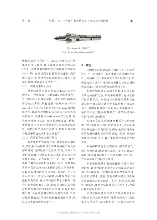
第1期使用寿命和可靠性[49]。
Arrow 3S 自锁式打捞器采用弹卡机构,用于连接钻具总成的套筒(图9),其横截面积比传统打捞器截面积减少5%~18%,有效提高了打捞器下放速度,提高取心效率;打捞器连接钻具总成后,具有自动锁定机构,提高施工安全度[50]。
2.3.2薄壁绳索取心钻具薄壁绳索取心钻具为Boart Longyear 公司研制的一种绳索取心工具系统,包括薄壁岩心管、薄壁钻头和薄壁钻杆。
以普通的NQ 绳索取心钻具为例,钻孔直径(钻头外径)Φ75.7mm ,岩心直径(钻头内径)Φ47.63mm ,而同规格的NQTK 薄壁绳索取心钻具在钻孔直径不变的情况下,可获得Φ50.67mm 的岩心直径,钻头壁厚减少1.5mm 。
相比常规绳索取心钻具,薄壁绳索取心钻具质量更轻,钻头所需钻压低,可配合轻型钻机以高转速、低扭矩提高硬岩地层中钻进效果和取心质量[51]。
2.3.3高效长寿命金刚石钻头随着铀矿勘查深度加深,减少换钻头的次数,降低提下钻次数可以有效缩短提下钻具的辅助时间,提高钻探作业效率,因此,高效长寿命的绳索取心金刚石钻头技术也是钻探技术发展的方向。
安百拓提出“一孔一钻头”理念,研制了JET26型高胎体金刚石钻头,该类型钻头胎体高度为26mm ,采用高强度大体积胎块,以保证长时间内的胎体强度,胎体内、外有半高水口设计,增加冷却面积;胎块端部水口处进行倒角设计,减少回转扭矩和水力损失。
配套的长寿命耐磨扩孔器,保径采用较大的热稳定聚晶金刚石(TSP )条进行加固,配合天然金刚石粒,并在高磨损区增加金刚石含量,以更好地控制磨损;保径区域设有磨损指示槽,用以表示扩孔器磨损程度[52]。
3结论1)国外铀矿勘查钻探中偏向于多工艺综合应用,同一区块或同一钻孔中设计常采用两种及以上的钻探工艺,形成多工艺组合钻探技术,以满足地质人员对不同深度地质体岩心和岩屑的研究需求,并达到经济高效的勘查目的。
2)西方铀资源大国勘查钻探设备以全液压动力头钻机为主,钻机采用履带自行或轮胎自行装载形式。
Horizontal Directional Drill Hole Drill end of the study andapplicationof a drill hole end of a composition and function.Construction of drill hole orientation : drill pipe, a launcher tube and a guide to accommodate bit.Construction of drill hole orientation with drilling, to change, through magnetic and drilling fluid delivery functions. Coordinated by computer control, in strict accordance with the design of the track has been completed oriented hole. Drilling is drilling high pressure liquid jet cutting board and bit accomplished; Bits board and the installation of boards of drilling teeth. Rotary drilling bit at the time supporting Cutting role in promoting the drill pipe at changes to the role; transmitters placed to accommodate tube launcher, to accommodate the opening of a Magnetic planters, Non-metallic materials and sealed to prevent the entry of high pressure drilling fluid, launch vehicles by the electromagnetic field Magnetic tank fired. Internal drill pipe and drill should provide sufficient access to meet the drilling fluid flow needs.2, the construction of bore hole : drill pipe, the first to expand, the rotary joint drill pipe and back to Rafah. When the guide hole drilling is completed, unloaded oriented bit, to accommodate tube launchers and connect with reverse bore bit and rotary joint, Then after the rotary joint drill pipe connected to Rafah, to Reamer drilling. The large diameter holes, a number of bore drilling, hole diameter gradually expanded to the size requirement.3, back to Rafah Pipeline Construction hole : drill pipe to Rafah, to expand first, rotating joints and pipe-drawing tools. When the bore drilling is completed, the drill pipe to Rafah after expanding access to the first and rotary joint, After the rotary connector connected pipe-drawing tools and the laying of pipelines to be anti-expansion Pipeline.2, the main drill a research and application, the drill pipe drilling pipe construction quality is the key to success. Construction of the pipe and caused damage to the drill pipe connecting the end of drill hole of the lost, whether to expand or expensive first mud motors, and pipelines. As the drill pipe construction of HDD technology to the success of a basic role, in recent years, drill pipe manufacturers have continued to adopt advanced technology to improve the structure of the pipe to improve its performance and quality. Currently, the main HDD drill pipe into theoverall style and welded two structural forms. Friction welding type of drill pipe drilling pipe achieve the best combination of structure, which means that in order to meet different needs. Performance of different materials can be used in different parts of the pipe. Friction welding drill pipe with high mechanical properties, wear resistance, light weight, good flexibility, a convenient way to different forms of threaded joints with different specifications of the pipe welding portfolio. Mount Sassafras drill pipe-welding technology is the key to the quality of welding, welding and heat treatment process control properly, Friction welding connection strength should reach even higher than the base material itself intensity. To ensure the quality of welding. foreign manufacturers for the manufacture of drill pipe friction welding equipment has been used advanced computer control and data recording technology. Through the monitoring system to ensure that every root of all drill pipe welding parameters in accordance with prior to the numerical implementation. In other words, a group of drill pipe in any one drill pipe, are strictly controlled in the context of tolerance, by the computer monitoring system to ensure that the welding performance consistency. And drill pipe through a single test, a number of drill pipe to provide each of the roots of the pipe complete, reliable performance data. After welding overall electromagnetic induction heat treatment, the whole process is an important stage. In recent years, considerable research through research and testing, now be able to make a welded seam mechanical properties to meet or surpass the performance of the base material itself, including durability, welding safety aspects. In order to improve the surface hardness thread, thread itself to prevent any possible occlusion, the post-processing on the surface of the nipple. Thread particular part should be carried out nitriding treatment. Drill pipe used in the manufacture of steel pipes used high-grade seamless steel tubes, and after quenching and tempering. Friction welding drill pipe Another advantage is being able to drill pipe internal drilling fluid channel design. Within which the nipple holes in the design of the Corridor full consideration to minimize the liquid through the hydraulic losses Special connecting thread is the first reduction of the loss, will greatly enhance the drilling fluid system efficiency. Threaded joints in the design using the top of the basket, the landscape of conical threaded design that can connect to increase strength, can in no additional washers with the help of the enclosed play a very good role. Practice shows that the use of more powerful drill holes and underground drilling equipment, maximum hole diameter and the smallest curvature radius, on the special needs of high-quality designof the drill pipe to meet the construction requirements.2, guided boring BHA(1) Universal : Universal Detection device for capacity, Variable bit to the plate-and cutting tools. It is normally used in soft soil and backfill soil construction, replacement of hard-bit teeth, hard formation for the construction, including the hard soil, rock, gravel and soft rock.(2) Rigid-formation comprising : Definitive detection devices installed capacity, belt-injection tube bending and (a) separate from the spray head, apply to soft soil controllable jet construction; (b) rock drill, as applied to drilling mixed layer, In hard rock section allows rotary drilling bits.(3) soft-rock composition : Definitive detection devices installed capacity, hammer, Hammerhead applicable to the hard ground and soft rock drilling high penetration and to(4) Rock : Definitive detection devices to accommodate devices, change the connector, mud motors, bits of rock to rock Drilling 3, used to expand drilling hole(1) with long shafts to extend the first features : 30 degrees cone shape, conducive to efficient cutting and squeezing soil; access to a variety of back end and threaded connection forms; forward and backward drilling fluid spray nozzle of the can for TC-rock teeth; Groove can be used to efficiently remove cuttings; Dimensions 8 "(200mm) a 20" (500mm) applicable to the general condition of the project, in the density of clay, gravel and mud-rock clay soil (gravel, cobble, etc.) construction, both warm-cutting with a knife and squeezed Cone for the composite function with high efficiency of the construction. Installation TC rock cutting teeth, can improve cutting. Generally applied to medium hardness of the soil, and are particularly suited to the hard rock and soil layer construction.(2) mid-knife to expand on features : open drilling body 30 degrees conical cutting arm, In comparison with the extrusion is excellent BTA and mixed role. Is a unique way to expand is omnipotent, in the sand, soft soil, clay and concrete compound layer construction with excellent performance, to be effective so that the soil mixed with the mud flow into the mixture has the ideal BTA and powerful mixing. Dimensions 8 "(200mm) a 20" (500mm).(3) spin-barrel-back expansion device features : suitable for medium and large drilling rig; open drilling body, three-arm design. with high efficiency and the cutting ability of BTA. Replacement rock cutting teeth can be replaced by the forward andbackward nozzle, the standard size of 12 "(300mm). Welding with industry standard API 5C6. generally used, broken clay soil superior extrusion type, This trace was excellent cutting properties and BTA, often with a barrel-to expand the use of devices together.(4) barrel-type device to expand features : suitable for medium and large rigs. 30 degrees around the cone; Replacement rock cutting teeth; both before and after the end can be replaced with the nozzle; standard size 12 "(300mm). Barrel - type device to expand in clay, gravel soil, aggregates and construction with the rock cutting and excellent extrusion properties, used mainly for extrusion soil (soft clay, peat), in soil squeezed out holes and maintain.水平定向钻机孔底钻具的研究与应用湖南工业大学机械工程学院机本0302班12号李洪光(译)一、孔底钻具的组成与功能1、导向孔施工钻具组成:钻杆、发射器容纳管和导向钻头。
16.2 DrillingDiamond drills are used in a wide range of applications in the construction and mineral industries. To give some indication of these applications we begin by considering the drilling of stone and concrete for the construction industry, and then discuss the various types of bits used for deep drilling in the oil industry.16.2.a Impregnated tube drillsFigure 16.20 shows example of tube drills of the type used to drill holes of the order of 20 mm to 400 mm diameter and up to perhaps 5 m deep through concrete and other structures with a minimum of disturbance to the surroundings. The drill consists essentially of a steel tube with curved impregnated segments of diamond brazed to its working edge. Thus the drill is rather similar in design and operation to the impregnated saws described in the previous section, and cuts an annular hole leaving an isolated central core of concrete or stone.Figure 16.20 Range of diamond tube drills for drilling masonary. (MG utensili diamantati s.p.a., Torino)Practical details and examples of the use tube drills are given by Smith(1974). The design of the diamond segments is determined by the same considerations as apply to the design of segments for sawing as discussed above. Some results on how drilling rates and wear of the segments depend on grit size and concentration, and on the power applied to the drill, are given by Van Biljon and Swersky (1975). As in all types of drilling the coolant plays an important role in removing the drilling debris. This is achieved in tube so that the coolant may be forced down the inner annular space between the tube and the rock and then up the other annular space on the outside of the tube. The effects of different types of additives in the coolant are discussed in Section 16.3.16.2.b Surface set diamond for deep drillingOil wells are commonly drilled to depths of over 5000 m using highly developed techniques with sophisticated methods monitoring the progress of the work. A good general view of the general arrangements and problems involved in deep drilling is given by Jenner (1984) but for our purpose it is sufficient to note that the holes are bored by a drill bit at the end of a drill rod which is extended length by length as the hole deepen. The diameter of the bit depends on particular circumstances but bits are available in size ranging perhaps from 20 mm to 400 mm diameter. The bit is forced down on the rock by the weight of the drill rod, and rotated by a torque from the surface transmitted down the rod or produced by a turbine mounted above the bit and driven by the flow of coolant.In order to cool the bit and carry away the drilling debris a drilling fluid is pumped down the center of drillrod to pass through nozzles in the bit and then back up through the outer annular space between the rod and the walls of the hole. This fluid may be essentially water or a mud, the latter being a water-based mud suspension selected to give optimum performance for a particular well, talking into account the cooling power required, the removal of debris, and other effects such as possible interactions between the fluid and the walls of hole.All bits for deep drilling were formerly made with steel or tungsten carbide but diamond bits offer two considerable advantages. first, their superior strength and hardness enables an adequate penetration rate to be achieved in very hard rocks which would otherwise be difficult to drill. second, diamond bits drilling softer rock may wear much more slowly than other bits because of their high abrasion resistance, and low wear is particularly important because a worn bit can only be replaced by pulling up the drill rod, length by length. Hence the time and cost of changing a bit is considerable, so even though diamond bits are much more expensive they can lead to large savings.A typical diamond bit for deep drilling is shown in Figure 16.21. In this type of bit the diamonds are located individually on the surface of a matrix such as tungsten carbide, and are described as surface set. Note the side bars which contain smaller diamonds and prevent undue wear of the sides of the bit. the centre of the bit is recessed because the diamonds close to the axis of rotation have a much smaller velocity and would suffer damage if they came directly into contact with unbroken rock. Note also the channels or waterways between the diamond pads to permit adequate flow of the coolant. For a general description of variants of this of bit see Panhorst (1978).Figure 16.21 Surface-set diamond bit for oil drilling (Anon, 1985)The size of the cutting diamonds in surface set bits ranges from about 4 per carat to 20 per carat depending on the type of rock involved. The action of the bit is first to break up the rock surface by crushing or plastic grooving under the loading of the individual diamonds (as described below). Then the damaged material is removed by the subsequent passage of other diamonds and carried away by the flow of the coolant. The volume of rock removed by a diamond will depend on how high it stands above the general level. Therefore lager diamondswill remove more material but will also experience greater forces. Hence, when drilling very hard rocks where the forces in any case are high it is preferable to use smaller diamonds. The considerations involved in the connection with sawing in Section 16.13.d. The use of PCD material in surface set bits is described in Section 16.2.c.Another important type of surface set bit is the so-called core bit. A bit of the type shown in Figure 16.21 breaks up all the rock in the hole, which is then removed as debris. However, when drilling to prospect for oil or minerals it is necessary to obtain samples of the solid rock. This is done by using a core drill with a form somewhat similar to the tube drill described in the previous section. As the bit drills down, a core of solid rock is left in the end of the drill rod and is brought to the surface by some suitable arrangement. Figure 16.22 shows a detail of diamonds set in such a drill.Figure 16.22 Detail of a surface-set diamond core bit (Hill, 1975)Deep drilling is a complex operation and successful economic results are only achieved by taking into account many considerations, see for example a case history given by Barnett,Jeansome and Mitchell (1988). Even to analyze the performance of the bit one must take into account the forces on the diamonds, the temperature, the part played by the debris, the action of the coolant, the response of the diamond, the nature of the rock being drilled, the last being a particularly large variable. We now briefly outline some experiments and calculations which have been made on these lines.Appl and Rowley (1968) considered the cutting action of a single diamond moving under load across the surface of a rock. As the diamonds in a drill are generally of a somewhat rounded shape they were assumed on average to be spherical. A calculation was then made of the volume of volume of material removed and the material behaves plastically. Proceeding in this way, and taking a value for the resistance to plastic deformation obtained from experiments in which rocks were indented with a wedge shaped tool (Gnirk and Cheatham, 1965), the authors obtained some fairly good correlations between theory and experiment. That is, their values for the cutting or friction force as a function of the normal force and the radius of the diamond were similar to experimental results obtained by Garner (1967) on an Indiana limestone under simulated borehole conditions with pressures up to 300 atm.The above analyze was extended to cover the performance of a drill bit in which the diamonds are either randomly or uniformly spaced (Rowley and Appl, 1969). These authors proceeded by assuming a certain penetration or volume removal rate, and hence deduced the mean volume of material plastically displaced by each diamond per revolution of the bit. Then, using values of the strengths of various rocks available in the literature, they calculate both the force on the diamonds and the corresponding load on the bit required to produce the assumed penetration rate. They thus obtained curves for the penetration rates as functions of the load on the bit and its rotary speed in reasonable agreement with direct measurements in the literature.A further analyze was made by Moore, Walker and Appl (1978) to include the effects of wear by assumingthat the originally spherical diamonds wore to give plane wear flats. These authors gave curves which show fair agreement with experiments but more extensive measurements of wear and penetrations rates are needed to obtain a conclusive picture. The authors also found it necessary to needed to introduce empirical adjustments to allow for variations of drilling efficiency with the input power, the bit velocity and the type of fluid.16.2.c PCD cutters for deep drillingWhen PCD first became available various attempts were made to replace the single crystal diamonds in drill bits by similarly shaped blocks of PCD. Even though PCD material is more resistant to cleavages and fracture these first attempts were not very successful. (We return to this possibility in Section 16.2.e) However, it was soon realized that PCD could be used to make a quite different type of bit which gives a good performance with long life in rock of soft to medium hardness, see for example Golis (1983) and Paterson and Shute (1982).Figure 16.23 Diamond bit with PCD cutters for oil drilling (Dieckmann, 1988)Figure 16.23 shows an example of a PCD bit consisting of a steel body which carries a number of blocks of PCD which act as cutters. Figure 16.24 gives a detail of a typical PCD cutter mounted on a steel stud which fits into the body of the bit. As described in Section 13.3 the actual PCD is generally in the form of a layer about 1 mm thick grown on a thicker base of tungsten carbide which can be readily brazed on to the steel stud. (Sometimes the carbide may also extend round the side of the PCD to give further strength.) Working in relatively soft rocks the cutters behave quite differently from surface set diamonds, and cat rather as cutting tools with a negative rake. As shown schematically in Figure 16.25 these cutters create small chips of rock which may coalesce under the high ambient pressures to form quite lengthy chips, see for example Warren and Armagost (1988). Note also that because the tungsten carbide base wears back faster than the PCD, the cutters exhibit a self-sharpening action which tends to maintain a sharp edge of diamond (Figure 16.26).Figure 16.24 Mounting of a typical PCD cutter (after Hooner and Middleton, 1981)The different nature of the rock removal process when using a bit with PCD cutters is particularly evident in an experiment described by Clark (1988) on the drilling of a hard and abrasive Pennant sandstone. Figure 16.27 shows the penetration rate versus the depth drilled for three similar bits working under different loads. As is to be expected the higher loads produce the greater penetration rate, and the rate falls off with increasing depth presumably because the bit is becoming blunt. Also the rate wear of the bit, as shown by the decrease in penetration rate with depth, is less for the higher loads and penetration rates. The result may appear surprising but arises because a greater load on PCD cutters revolutions. Hence, as the wear at the number of revolutions, the wear is not so great at the higher loads.Figure 16.25 Sketch to illustrate chip formation by a negative rake cutter (Warren and Armagost, 1988)Figure 16.26 Diagram to show the self sharpening effect on PCD cutters (Hoover and Middlecton, 1981)The design of a bit must ensure the efficient removal of the rock debris by the drilling fluid or mud in order to avoid it balling up on the cutter. In addition, the types of rock to be drilled vary greatly in their properties.Therefore there is considerable variety in the geometric form of the drill bits, both in the arrangement of the cutters and the layout of the fluid nozzles, see for example Feenstra(1988a) and Kerr (1988). Examples of the geometries of the cutters themselves and their mounting on the steel studs are given by Dennis and Clark(1987). A useful review of current developments and possible future application is given by Feenatra(1988b).Figure 16.27 Penetration rates of PCD bits drilling Pennant Sandstone as a function of depth drilled and bitload (Clark, 1988)16.2.d Analysis of cutter performanceThe performance of the PCD cutters in a bit depends on a variety of factors including the hardness of rock, the cutter design and the wear of the PCD. It is obviously difficulty to simulate deep drilling conditions in the laboratory. In particular the ambient pressure is perhaps about 100 atm, the volume of mud flow is very large, and in softer rocks appreciable wear is only produced after long drilling. Hence information on the performance of cutters comes mostly either from reports of performance in the field or from laboratory experiments which may only approximate to real working conditions.Studies of the effect of varying the rake angle of the cutter (Figure 16.24) have been made by Hibbs and Flom (1978), Hough(1986) and Shafto (1985). However, only the latter author made an actual drilling experiment with a liquid coolant, Hough drilled with ‘air flushing’, and Hibbs and Flom simulated drilling by turning on a lathe. One of the more realistic sets of laboratory experiments is that of Warren and Armagost(1988) who drilled under a pressure of 8.6 MPa but only to depths of about a metre. However, although these distances are small the penetration rates took up steady values after drilling for only about 0.3 m. Values are given for the penetration rate and the torque on the bit when drilling limestones and shales as a function of the load on the bit for both new and worn cutters, using either oil- or water-based muds. The authors gives an informative discussion of their results including the effects of wear and of any balling of the mud around the cutters.One of the principal limitations to high rates of drilling is the need to avoid overheating the PCD. The standard type of PCD is less stable at high temperatures than single crystal diamond. Its greater expansion coefficient creates internal stresses on heating and its catalytic activity causes degradation of the diamond (Section 12.2.d). When PCD cutters are used to turn or drill rock at least two types of wear are involved (Lee and Hibbs, 1979; Hibbs and Sogoian, 1983). At low speeds the appearance of the worn surface is typical of the type of mechanical abrasive wear seen when the PCD is subjected to a rough polishing, while at high speeds there is a much larger component arising from thermal damage.It is difficult to quote an exact temperature above which thermal wear becomes important for three rather different reasons. First, the effect of a temperature depends on the time that the PCD to a metal shank in a few seconds and cause little damage even though a similar steady temperature would produce severe deterioration. Second, the temperature stability of PCD depends on the grain size (Section 12.2.d) and other characteristics ofthe particular proprietary brand of PCD in question. Third, a further complication is shown by an experiment on the wear rate rose markedly as the cutting speed increased above a certain value. This rise suggested the onset of thermal wear but micrographs of the worn surfaces showed a structure not much different from that at lower speeds. Hence there may be a temperature region in which the PCD begins to lose strength without obvious signs of disintegration. (Such behaviour is also suggested by the acoustic emissions observed by Mehan and Hibbs(1989) when heating a coarse grain PCD above 400℃as described in Section 12.2.d).Although the position regarding the onset and nature of thermal damage is somewhat obscure, one can still note some significant temperatures. It is clear that temperatures above about 800℃will cause rapid disintegration by thermal effects alone. It is also clear that considerably lower temperatures may produce a loss of strength. For example Clark and Shafto(1987) show that holding specimens for 30 min at various temperatures above 650℃produced lagre reduction in their useful life when turning a cylinder of granite, see also Ckark(1988). There is, however, not much information on the changes responsible for the increased wear.Although the temperature may greatly affect the performance of a PCD cutter, it is not easily measured in situ at the bottom of deep well. Therefore estimates of temperatures have generally been made either via simulation experiments or by calculations. Hibbs and Sogoian(1983) made detailed experiments with cutters on a vertical axis lathe making facing cuts on marble and sandstone (using a flood coolant). They observed that thermocouples in the PCD close to the wear flat registered temperatures ranging from about 100℃to 500℃depending on the type of stone, the cutting speed, and the condition of the cutters, increasing greatly as they because worn. (Measurements are also given of the wear and cutting forces without a coolant.)Attempts have been made to calculate the working temperature of cutters given the load on the bit and its rate of rotation. Using this approach one first calculates the normal force on each cutter and hence the friction force Fu which is responsible for the generation of heat. Virtually all the work done by the drill appears as heat at the cutters, and flows away from the PCD to either the rock or mud. To estimate these forces and heat flows, experimental values are required for the effective coefficient of friction between the cutter and the rock, for the thermal conductivity of the rock and the cutters, and for the coefficients of heat transfer from the cutters to the mud and in the mud. Hence the calculations involve a formidable programme but estimates of excess temperatures have given by Ortega and Glowka(1984), who quote values up to the order of 500℃; see also Glowka and Stone(1985). However, because of the difficulty of determining all various parameters and obtaining values of all the various physical constants, the principal importance of these calculations is not so much in the numerical values but to show how the temperatures is not so much in the numerical values but to show how the temperatures are affected by changes in the design factors.Figure 16.28 Progressive wear of a PCD cutter, see text (Zijsling, 1984)The complexity of the working conditions of a PCD cutter is further underlined by Zijsling(1984) who observed the form on a cutter in a simulated drill-hole experiment. The PCD layer in this cutter was mounted on a doubleblock of tungsten-carbide set in a matrix-type bit (Figure 16.28(a)). Initially with a new cutter the rock abrades the PCD, the carbide and the matrix, but as the matrix and carbide wear the forces are concentrated on the PCD (Figure 16.28(b), (c) and (d)). A further complication observed by Zijsing was that the edge of the PCD developed a wear land, as shown in Figure 16.29, with effectively a very high angle negative rake, and he argues that the volume under this land is filled with broken down rock or ‘rock flour’ which affects the temperature distribution. For further details of the various above calculation, see the original papers and comments by Feenstra(1988a).Figure 16.29 Sketch showing geometry of a cutting edge, see text (Feenstra, 1988a)16.2.e Thermally stably PCD bitsBecause of the temperature limitations on the use of PCD bits described in the previous section there is an increasing interest in the more thermally stable types if PCD described in Section 12.2.d. We mentioned in Section 16.2.a that soon after the production of the first PCD material attempts were made to use pieces of PCD in surface set bits in the same way as single crystal diamond. These attempts were not very successful, one of the difficulties being that the hard rocks drilled by surface set bits give rise to high forces and high temperatures which reduced the strength of the PCD. However, the thermally stably variants of PCD now available will operate at temperatures up to about 1200℃and are being used successfully in surface set with small oriented cubes of thermally stable PCD. For further details of the design and performance of this type of tool see Clark and Shafto (1987) and Stewart, Falter and Tomlison(1988).Figure 16.30 Surface-set diamond core bit using oriented cubes of thermally stable PCD (Stewart, Falterand Tomlinson, 1988)The advantages of the various types of thermally stable PCD suggest that we may expect its increasing development and use. At present this material is only available in relatively small pieces and therefore cannotreplace the large PCD blocks used as drill cutters. However, experiments are now being made with so-called mosaic cutters in which the working surface of a PCD cutter is inset with pieces the thermally stable material is not available on a base such as tungsten carbide which is used to give additional strength to normal PCD.。
电动机端盖专用钻床外文文献Small and medium-sized asynchronous motors generally use cast iron end caps with bearings, and the end caps are provided with bearing chambers for placing bearings and blocks matched with the machine base. The end caps serve to support rotating components, determine the relative position between the rotor and stator, protect the interior of the motor, and guide air. The rigidity and dimensional accuracy of the end cover structure, as well as the geometrical and positional tolerances of the end cover and bearing chamber directly affect the uniformity of the air gap between the stator and rotor, and even the quality level of the motor. Therefore, the key problem in the end cover processing is how to control the accuracy of the joint and the bearing chamber, the coaxiality between them, and the circular runout of the joint step end facing the axis.Small and medium-sized asynchronous motors generally use cast iron end caps with bearings, and the end caps are provided with bearing chambers for placing bearings and blocks matched with the machine base. The end caps serve to support rotating components, determine the relative position between the rotor and stator, protect the interior of the motor, and guide air. The rigidity and dimensional accuracy of the end coverstructure, as well as the geometrical and positional tolerances of the end cover and bearing chamber directly affect the uniformity of the air gap between the stator and rotor, and even the quality level of the motor. Therefore, the key problem in the end cover processing is how to control the accuracy of the joint and the bearing chamber, the coaxiality between them, and the circular runout of the joint step end facing the axis. [81] Zhang Na Simulation of Permanent Magnet Synchronous Motor Based on SVPWM Algorithm [J] Journal of Anhui Electronic Information Vocational and Technical College, 2018,17(02)[82] Sun Kai, He Bona, Sarah Odofin, Guyu Research on fault diagnosis of induction motor current sensor [J] Electric Drive, 2018, 48 (04)[83] Qian Jianzhong, Li Jiasong, Ni Hailin, Wang Zhao Experimental study on the change of iron loss performance by annealing of variable frequency compressor motors [J] Electrical Technology, 2018, 19 (04)[84] The application of direct drive permanent magnet motors in coal mines [J] Low Carbon World, 2018 (04)[85] Yao Changqing, Analysis and Research on the Control Fault of Energy Consumption Braking Based on the Motor Star Delta [J] Internal Combustion Engine and Parts, 2018 (07)[86] Liu Haiying, Analysis and Elimination of Common Faults of Agricultural Motors [J] Use and Maintenance of Agricultural Machinery, 2018 (04)[87] Gao Qinhe, Dong Jiachen, Shao Yajun, Niu Hailong, Chen Zhixiang. Development of virtual experimental platform for motor characteristics based on Matlab/GUI [J] Laboratory Research and Exploration, 2018, 37 (04)[88] Wang Baoping FANUC 0i-TD system based on the realization of servo motor spindle control function [J] Manufacturing Technology and Machine Tools, 2018 (05)[89] Wu Senfeng, Performance Analysis of Shearer Driven by Electric Motor and Hydraulic Torque Converter [J] Industrial and Mining Automation, 2018, 44 (06)[90] Li Linhai, Design and Analysis of Flameproof Variable Frequency Speed Regulation Three-phase Asynchronous Motor for Scraper Conveyor [J] Mechanical Management Development, 2018, 33 (04)。