博世力士乐使用说明、
- 格式:docx
- 大小:465.77 KB
- 文档页数:9
德国rexroth泵PGZ使用说明力士乐致力于为各类机械和系统设备提供安全、精准、高效以及高性价比的传动与控制技术。
公司融合全球的应用经验,研发创新的产品,为行走机械、机械应用与工程、工厂自动化及可再生能源每一个细分市场的客户量身定制系统解决方案及服务。
博世力士乐同时为客户提供各种液压、电子传动与控制、气动、齿轮、线性传动及组装技术。
公司业务遍及全球80多个国家,拥有37,500多名专业员工,2012年全球的销售额近65亿欧元。
业务部门行走机械:建筑机械、物料搬运设备、农业与林业机械、商用/公路汽车机械应用与工程、工厂自动化:运动机构、汽车工业、采矿业、石油和天然气钻探(地面)、舞台技术、化工业、印刷与纸张处理、能源技术、物料输送、玻璃机械制造、橡胶加工、半导体和电子工业、木工行业、水平定向钻机、发动机、塑料机械和拉磨机、冶金、矿山设备、组装与装卸、挖泥船、近海工程、加工与包装、测试技术、回收和垃圾处理、船舶工程、运动模拟技术、太阳能、机床(切削)、水利工程、盾构机、金属成形机床和压机、传送技术、流体动力研究、船厂设备、水泥工业、制糖工业、纸浆和造纸机械。
可再生能源:风能产品组群驱动技术、电子传动与控制技术、浇注成型技术、齿轮技术、工业液压、线性传动技术、行走液压、组装技术、气动、拧紧与焊接技术Gerotor泵具有恒定排量PGZ帧大小4,5尺寸20 (140)最大工作压力15bar最大排量136.3cm?特征具有固定排量的低压泵极低的运行噪音适用于广泛的粘度和速度范围出色的吸力特性可与轴向柱塞泵,内齿轮泵和叶片泵组合使用用途:工业或移动应用中的低压冷却,过滤器或润滑剂回路,例如塑料加工机器,机床,压力机和风力涡轮机。
相关型号推荐PR4-3X/1.60-700RA01M03,PR4-3X/1.60-700RA01V01,PR4-3X/2.00-700RA01M01,PR4-3X/2.50-700RA01M01,PR4-3X/2.50-700RK01M01,PR4-3X/2.50-700RA01V01,PR4-3X/3.15-700RA01M01,PR4-3X/3.15-700RG01M01,PR4-3X/4.00-700RA01M01,PR4-3X/4.00-700RG01M01,PR4-3X/6.30-700RA01M01,PR4-3X/6.30-700RA01M08,PR4-3X/6.30-700RA01V12,PR4-3X/8.00-700RA01M01,PR4-3X/8.00-700RA01M02,PR4-3X/8.00-700RA12M01,PR4-3X/3.15-500RA01M01,PR4-3X/5.00-500RA01M01,PR4-3X/6.30-500RA01M01,PR4-3X/8.00-500RA01M01,PR4-3X/10.00-500RA01M01,PR4-3X/10.00-500RA12V01,PR4-3X/16.00-500RA01M01,PR4-3X/20.00-500RA01M01,PR4-3X/16,00-500RA12M01PR4-3X/2,00-700RA01M01R900452697产品描述建立PGZ型液压泵是具有恒定排量的齿轮泵。
The Drive & Control CompanyRexroth变频器Fe系列简易手册版本04R912004816Bosch Rexroth AG更改过程出版颁发日期备注DOK-RCON01-FE*********-IN01-ZH-P2013年6月第一版DOK-RCON01-FE*********-IN02-ZH-P2013年11月增加了新功能DOK-RCON01-FE*********-IN03-ZH-P2014年11月增加了新功能DOK-RCON01-FE*********-IN04-ZH-P2014年12月固件升级关于此文档该《简易手册》基于产品《使用手册》,《使用手册》包含产品的详细数据。
在未通读产品《使用手册》中的安全相关章节内容以及产品标准供货所附《安全说明》前, 请勿操作该产品。
参考文档如需其他类型或语言的文档, 请联系当地代理商或访问以下网址/fe版权© 博世力士乐(西安)电子传动与控制有限公司 2014该文档以及其中的数据、技术规格和其它信息均为博世力士乐(西安)电子传动与控制有限公司的专有财产。
未经同意,禁止复制或供第三方使用。
责任规格数据仅用于产品说明,如果未在合同中明确规定,不得视为对特性的保证。
本公司保留关于该文档内容和产品可用性的所有权利。
RS-a892fbc73b3b8d410a6846a500c72470-4-zh-CN-5Bosch Rexroth AG目录目录页数1 结构安装 (1)1.1 目视检查 (1)1.2 环境条件 (1)1.3 安装条件 (2)1.4 外型尺寸 (3)2 电气安装 (7)2.1 电缆规格 (7)2.2 主回路端子 (12)2.3 控制信号端口的连接 (15)3 参数设置 (20)3.1 操作面板 (20)3.2 启动 (21)3.3 操作说明 (22)3.4 参数列表 (22)4 故障指示 (42)DOK-RCON01-FE*********-IN04-ZH-P IBosch Rexroth AGII DOK-RCON01-FE*********-IN04-ZH-P1 结构安装1.1 目视检查打开变频器包装后, 请进行目视检查。
目录目录页数1 结构安装 (1)1.1 目视检查 (1)1.2 环境条件 (1)1.3 安装条件 (2)1.4 尺寸 (3)2 电气安装 (6)2.1 电缆规格 (6)2.2 主回路端子 (8)2.3 控制信号端口的连接 (9)3 设置参数 (13)3.1 操作面板 (13)3.2 起动 (14)3.3 操作指导 (15)3.4 参数列表 (16)4 故障指示 (36)结构安装1 结构安装1.1 目视检查打开变频器包装后,请进行目视检查。
检查以下项目:●供货型号是否正确●设备是否有损坏●运输过程中是否造成机箱划痕、裂痕或凹痕如果发现任何上述问题,请联系Bosch Rexroth分销商。
1.2 环境条件为了保证变频器正常运行,变频器的安装环境必须符合下表所列数据。
①:参见《使用手册》“10.3:电气参数的降额”。
表格 1-1: 环境条件1.3 安装条件变频器根据额定值的不同,分为不同的外型尺寸。
为了达到理想的散热效果,必须保证下图所示变频器与相邻物品之间上、下的最小安装距离。
插图 1-1:安装条件●上图所示变频器为机箱1至3。
上述最小安装距离适用于机箱1至机箱4。
●必须垂直安装变频器。
●如果将一台变频器安装在另外一台之上,确保变频器进气口温度不超过上限值(参见 第 1.2 章 "环境条件" 第 1 页 )。
如果超过上限,建议在变频器之间安装隔板,防止上升的热空气被吸入上面的变频器。
Bosch Rexroth AG 结构安装1.4 尺寸表格 1-2: EFC 3600尺寸①:完整型号(类型编码)为:EFC3600-xKxx-xPx-xDA-7P-NNNN ,参见《使用手册》17.3章附录三:类型编码。
②:安装EFC 3600机箱1、2、3,需要2颗螺钉。
③:安装EFC 3600机箱4,需要4颗螺钉。
Bosch Rexroth AG结构安装Bosch Rexroth AG 结构安装插图 1-2: 机箱1、2、3Bosch Rexroth AG结构安装插图 1-3: 机箱42 电气安装2.1 电缆规格2.1.1 主回路配线变频器根据额定值的不同,分为不同的外型尺寸。
前 言感谢您选用博世力士乐电子传动与控制(深圳)有限公司的变频调速器(以下简称变频器)!CVF - G3系列、CVF - P3系列变频器是自主开发、生产的高性能变频器,该产品采用高品质的元器件、优质材料,并融合高新微电脑控制技术制造而成。
本使用手册提供如下产品系列的操作指南:(1) CVF-G3系列通用型变频器(2) CVF-P3系列风机、水泵专用型变频器本手册阐述了用户安装配线、参数设定、故障诊断和故障排除、日常维护等相关事宜。
为确保能正确操作此系列变频器,发挥其优越性能,请在装机之前,详细阅读本使用手册,并请妥善保存,或将本手册交于该机器的使用者。
如对于本变频器的使用存在疑问或有特殊要求,请随时联络本公司的各地办事处或经销商,也可与本公司总部售后服务中心联系,我们将竭诚为您服务。
我们一直致力于产品的不断完善,故本系列变频器的相应资料(操作手册、宣传资料等)如有变动,恕不另行通知。
欢迎选用本公司其它系列变频器产品:CVF-ZS系列注塑机专用型变频器CVF-ZC系列注塑一体化柜机CVF-LS1系列拉丝机专用型变频器CVF-LY1系列络筒机/印花机专用型变频器CVF-S1 系列单相小功率变频器CVF-SMP系列简易型单相小-1-功率变频器CVF-MN1 系列迷你型单相小功率变频器CVF-V1 系列高性能矢量型变频器开箱时,请认真确认以下内容:1.产品是否有破损,零部件是否有损坏、脱落现象,主体是否有碰伤现象;2.本机铭牌所标注的额定值是否与您的订货要求一致;3.本公司在产品的制造及包装出厂方面,质量保证体系严格,但若发现有某种检验遗漏,请速与本公司或供应商联系,我们将在第一时间为您解决。
变频器型号说明:-2-目录1.注意事项...................................................11.1 安全标识定义..........................................11.2 安装注意事项..........................................11.3 使用注意事项..........................................21.4 报废注意事项..........................................42.安装与配线..............................................52.1 产品技术指标及规格.................................52.2 系列型号说明.....................................72.3 安装环境要求.................................82.4 变频器的安装尺寸...................................82.5 操作面板尺寸...................................102.6 盖板的拆卸与安装....................................112.7 操作面板的拆卸与安装................................112.8 安装方向与空间......................................122.9 变频器的配线........................................132.10 回路端子台的配线....................................212.11 JP跳线说明.........................................282.12 接线说明............................................293.操作与运行 .............................................353.1 面板操作............................................353.2 名词术语说明.......................................363.3 面板功能说明....................................393.4 键盘操作方法.....................................403.5 变频器的运行.....................................444.功能参数一览表 .........................................474.1 基本运行参数(b参数)................................474.2 中级运行参数(L参数).................................48- 3 -4.3 高级运行参数(H参数).................................514.4 状态监控参数一览表...................................554.5 保护功能及对策......................................574.6 故障记录查询........................................585.功能详细说明 ............................................605.1 基本运行参数(b参数)..................................605.2 中级运行参数(L参数).................................685.3 高级运行参数(H参数).................................836.维护与保养 ............................................976.1 日常检查与保养.......................................976.2 定期维护.............................................986.3 易损部件的检查与更换.................................996.4 存放及保修............................................99 7.使用范例.................................................1017.1 面板控制起、停, 面板电位器设置频率.....................1017.2 三线制控制模式........................................1027.3 外部控制方式、外部电压设定频率.........................1037.4 多段速运行、外部控制方式...............................1047.5 可编程多段速控制......................................1057.6 多台变频器的联动运行(群组控制) .......................1067.7 用变频器构成闭环控制系统..............................1107.8 用上位机(PC)控制多台变频器...........................111 8.选件.....................................................1138.1 远控线缆和远控适配器................................1138.2 供水附件............................................1138.3 制动组件............................................113- 4 -附录1:RS485通讯协议........................................115附录2:供水附件的应用.......................................126- 5 -- 6 -第一章 博世力士乐电子传动与控制(深圳)有限公司 注意事项为了确保您的人身、设备及财产安全,在使用变频器之前,请务必仔细阅读本章内容,并在以后的搬运、安装、运行、调试与检修过程中遵照执行。
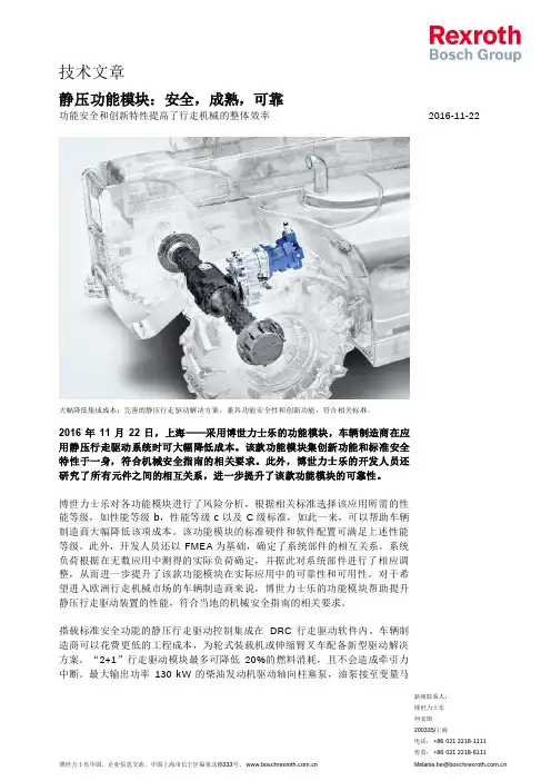
新闻联系人: 博世力士乐 2016-11-22静压功能模块:安全,成熟,可靠功能安全和创新特性提高了行走机械的整体效率大幅降低集成成本:完善的静压行走驱动解决方案,兼具功能安全性和创新功能,符合相关标准。
2016年11月22日,上海——采用博世力士乐的功能模块,车辆制造商在应用静压行走驱动系统时可大幅降低成本。
该款功能模块集创新功能和标准安全特性于一身,符合机械安全指南的相关要求。
此外,博世力士乐的开发人员还研究了所有元件之间的相互关系,进一步提升了该款功能模块的可靠性。
博世力士乐对各功能模块进行了风险分析,根据相关标准选择该应用所需的性能等级,如性能等级b ,性能等级c 以及C 级标准,如此一来,可以帮助车辆制造商大幅降低该项成本。
该功能模块的标准硬件和软件配置可满足上述性能等级。
此外,开发人员还以FMEA 为基础,确定了系统部件的相互关系。
系统负荷根据在无数应用中测得的实际负荷确定,并据此对系统部件进行了相应调整,从而进一步提升了该款功能模块在实际应用中的可靠性和可用性。
对于希望进入欧洲行走机械市场的车辆制造商来说,博世力士乐的功能模块帮助提升静压行走驱动装置的性能,符合当地的机械安全指南的相关要求。
搭载标准安全功能的静压行走驱动控制集成在DRC 行走驱动软件内。
车辆制造商可以花费更低的工程成本,为轮式装载机或伸缩臂叉车配备新型驱动解决方案。
“2+1”行走驱动模块最多可降低20%的燃料消耗,且不会造成牵引力中断。
最大输出功率130 kW 的柴油发动机驱动轴向柱塞泵,油泵接至变量马新闻联系人: 博世力士乐 2016-11-22达和定量马达。
驱动范围自动调节,可实现最高40 km/h 的行驶速度。
控制单元集成的软件可避免牵引力为零的情况出现,显著提升操作人员的舒适度。
该功能模块适合工作重量6~16吨,牵引力不超过120 kN 的行走和农业机械。
“动力换档”功能满足 DIN EN ISO 13849标准的安全要求,对手动和自动切换进行控制。
德国原装REXROTH泵使用材料说明REXROTH力士乐,REXROTH不仅是世界前100强公司,也是世界高科技企业之一,50多年来,BoschRexroth集团及BoschRexroth公司的业务部门致力开发专业型液压传动领域高科技产品,产品和品牌已享誉全球。
力士乐的产品是独特的,因为在世界市场上,目前没有其他的品牌能向顾客提供所有传动与控制技术,专门化与一体化并举。
正因如此,博世-力士乐在液压传动、控制及移动技术等领域成为了世界性的榜样。
力士乐(Rexroth)为工业及工厂自动化、行走机械、以及可再生能源等领域的客户提供传动、控制与移动解决方案;作为全球超过50万客户的共同选择,力士乐正不断为客户提供高质量的电控、液压、气动以及机电一体化元件和系统。
Rexroth-力士乐气动产品大量应用在钻修设备的气路上,以及Caterpillar 卡特匹勒与Allison艾里逊变速箱的配合中以实现动力的操作和控制。
以Rexroth-力士乐高性能的液压产品为依托,Rexroth向钢铁行业提供连铸、连轧等生产线的全套液压系统和液压元件。
BoschRexroth博世-力士乐在船舶和海洋钻井平台的液压和气动传动系统及控制方面具有渊博的经验,产品应用在钻井平台、推进系统、舵机系统、发动机控制系统等等业务部门行走机械:建筑机械、物料搬运设备、农业与林业机械、商用/公路汽车机械应用与工程、工厂自动化:运动机构、汽车工业、采矿业、石油和天然气钻探(地面)、舞台技术、化工业、印刷与纸张处理、能源技术、物料输送、玻璃机械制造、橡胶加工、半导体和电子工业、木工行业、水平定向钻机、发动机、塑料机械和拉磨机、冶金、矿山设备、组装与装卸、挖泥船、近海工程、加工与包装、测试技术、回收和垃圾处理、船舶工程、运动模拟技术、太阳能、机床(切削)、水利工程、盾构机、金属成形机床和压机、传送技术、流体动力研究、船厂设备、水泥工业、制糖工业、纸浆和造纸机械。
原装REXROTH轴向柱塞泵产品说明书力士乐柱塞泵是液压系统的动力机构,它将原动机(电动机、内燃机等)的机械能转变为液体的压力能。
力士乐柱塞泵可以分为容积式和非容积室(蜗轮式)两种。
力士乐柱塞泵非容积式有离心泵、轴流泵等,利用高速旋转的叶轮使进口产生真空吸入液体,并在出口连续输出压力液体。
这种泵进口与出口相通,效率随液体粘度增加而降低,并且输出液体量随出口压力升高而显着减少。
BOSCH博世REXROTH力士乐柱塞泵技术参数:用矿物油工作有效;(如用HF-流体见RC 90223,用环保液压油见RC 90221)工作压力范围-进油侧S口(进口)的绝对压力Pabs min绝对压力分钟:0.8 barPabs max绝对压力大:30 bar工作压力范围-出口侧在B口的压力额定压力pN 280 bar峰值压力pmax 350 bar(压力资料符合DIN 24312)间歇工作在负载时间为10%时,压力可达315 bar。
溢流阀块能限制泵的输出压力大值,此溢流阀块直接装在连接法兰上,请根据样本活页RC 25 880和RC 25 890另行订货。
壳体泄油压力泄漏油(L,L1口)大允许压力:高可比S口的进口压力高0.5 bar,但不得高于2 bar绝对压力。
柱塞泵A4VG90HWD1/32R-NZF001S柱塞泵A4VTG90HW/32R-NLD10F001S轴向柱塞泵A4VSO125DR/PPB13NOO变量轴向柱塞泵A4VSO180DR/30R-PPB13N00变量轴向柱塞泵A4VSO125DR/30R-PPB13N00柱塞泵A4VS0125DR/10R-PPB13N00柱塞泵A4VS071DR/10R-PPB13N00柱塞泵A4VS0125DR/22R变量泵A4VSO250EO2/30R-VPB13N00-SO2柱塞泵A4VG125EP2MT1/32-NZF02F021SH-S柱塞泵A4VSO250EO2/30R-VPB13N00-SO2变量轴向柱塞泵A4VSO180DR/30R-PPB13N00变量轴向柱塞泵A4VSO125DR/30R-PPB13N00油泵A4VSO180DFR/30R-PPB13N00柱塞泵A4VS0180DR/30R-PPB13N00轴向柱塞泵主泵A4VS0125DRG/30R-PPB13N00油泵A4VS071DR/30R-PPB13N00德国力士乐A4VG-125泵的配件主轴080121-001#轴向柱塞泵E-A4VSO250EO2/30R-VPB25N00-SO3轴向柱塞泵E-A4VSO250EO2/30R-VPB25N00-SO3柱塞泵A4VSO180DR/30R-FPB13N00恒压变量泵E-A4VS0125DR/22R-VPB13N00柱塞泵A4VSO180DR/30R-FPB13N00柱塞泵A4VS0180LR2G/30R-PPB13NOO柱塞泵A4VSO250LR2D/30R-PPB13NOO柱塞泵A4VSO250DR/30R-PPB13NOO泵A4VG56EZ2DM1/32-NSC02F003F柱塞泵A4VS0250DR/30RPPB13N00阀柱塞泵A4VTG71HW/32R-NLD10F001S柱塞泵A4VSG750HD/22R-PPH10NOO轴向柱塞泵A4VS07IDR/3XR轴向柱塞泵A4VS0125DR/3XR柱塞泵A4VG90EP2DT1/32R-NAF02F00柱塞泵A4VSO-250E02/30R-PPB13N00柱塞泵A4VSO-250DR/30R-PPB13N00液压马达A4VG40EP4DMT1/32L-NSC02F015PHREXROTH轴向柱塞泵的工作原理1)斜盘式轴向柱塞泵组成:配油盘、柱塞、缸体、倾斜盘等工作原理:V密形成——柱塞和缸体配合而成右半周,V密增大,吸油V密变化,缸体逆转< 左半周,V密减小,压油吸压油口隔开—配油盘上的封油区及缸体底部的通油孔2)斜轴式轴向柱塞泵特点:传动轴轴线与缸体轴线倾斜一γ角。
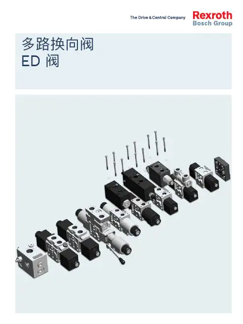
多路换向阀ED 阀2ED 多路阀 | | ED 多路阀 3博世力士乐推出“多路换向阀 — ED 多路阀手册”:根据具体应用,使用该手册可以简化多路阀元件选型。
我们的目标是制作一种非常方便查阅的材料(该材料不能代替产品样本)。
由于我们拥有完整的产品系列、清晰的型号体系以及各种可选项,该手册能有效指导用户选择所需的元件。
ED 多路阀可以替代传统的“六通换向阀”,同时 ED 多路阀元件可以“无限度”地进行组合,以满足用户的各种要求并提高设备的性能。
ED 多路阀手册的编写正是建立在这种 “ 片式 ED 多路阀”的理念基础之上。
ED 多路阀手册帮助用户完成多路阀元件的选型配置,构建控制执行机构(马达或油缸)的开关和比例电磁多路换向阀。
根据液压回路类别,参照该手册可以很容易地选择合适的多路阀元件以构建能够满足回路要求的系统。
手册中也包括了一些我们可以开发的适用于不同回路或应用的液压元件。
如果系统或应用对单联流量要求超过 80L/min,可以采用 ED 多路阀与 M4-12 / M4-15 阀组合使用的方案,构成“组合控制方案”。
应用:f 1. 随车起重机 f 2. 全路面起重机 f 3. 爬梯高空作业车 f 4. 车载高空作业车 f 5. 高空作业车 f 6. 叉车 f 7. 喷药车 f 8. 联合收割机 f 9. 伸缩臂叉车 f 10. 挖掘装载机 f 11. 挖掘机 f 12. 钻机 f 13. 垃圾车 f14. 扫地车简介应用及产品图片EDC 多路阀组合控制方案M4 + EDC + EDB 多路阀组合控制方案M4 + EDC + ED 多路阀EDD 多路阀图 1图 2从图 1 和图 2 中,我们可以看出 ED 多路阀与传统六通换向阀的区别。
对于传统控制阀(图 1),油泵通过阀的中位泄荷,而 ED 多路阀只有 4 个油口,因此需要专门的泄荷方法。
最常用的泄荷方法是采用如图 2 所示的 2 位 2 通电磁阀,或者使用逻辑元件。
2/52博世力士乐股份公司CS351/CC-CS351|3609929B45/2014-09CS351 | 3609929B45/2014-09博世力士乐股份公司3/54目录1关于本文档 (05)2一般安全说明 (06)3交付范围 (09)4产品说明 (10)5运输和存储 (31)6装配 (32)7调试 (34)8操作 (38)9维护和修理 (40)10废弃 (46)11拆卸和更换 (47)12处置 (48)13扩展和转换 (48)14故障诊断 (48)15技术数据 (49)16服务与销售 (52)语英4/54 博世力士乐股份公司CS351 | 3609929B45/2014-09以上所列数据仅用于对产品进行说明。
我们提供的信息不能作为对某种条件或某种应用适用性的声明。
所提供的信息不能免除用户自行判断和验证的义务。
请注意,我们的产品会经受自然磨损和老化。
© 本文档及其中所列的数据、规格和其它信息为博世力士乐股份公司独家所有。
未经许可,不得将其翻印或提供给第三方。
本文档以 PDF 文件的形式提供。
原始操作说明的翻译。
原始说明以德语制作。
CS351 | 3609929B45/2014-09 博世力士乐股份公司5/54关于本文档英语1关于本文档本手册包含有关 CS351/CC-CS351 紧凑型系统的安全和适当装配、运输、调试、操作、维护、拆卸以及简单故障诊断的重要信息。
有关紧凑型系统中使用的软件说明并不包含在这些说明中。
有关您可能需要的软件和操作的任何信息,请参阅 BS350 操作程序的联机帮助以及随附的 USB 系统记忆棒中的系统文档。
在使用紧凑型系统之前,请完整阅读这些说明,尤其是第 6 页的“一般安全说明”一章。
文档的范围此文档适用于 CS351 和 CC-CS351 紧凑型系统。
需要符合 VDI/VDE 2862 类别 A 文档的拧紧操作可以使用由 ErgoSpin 手持式拧紧机和 CS351E... 紧凑型系统组成的拧紧系统来执行。
Instruction ManualElectric Drives and ControlsPneumatics ServiceLinear Motion andAssembly TechnologiesHydraulicsRexroth IndraDrive Drive ControllersPower Sections HCS01R911325518Edition 06Rexroth IndraDrive Drive Controllers Power Sections HCS01Instruction ManualDOK-INDRV*-HCS01*UL***-IB06-EN-PRS-49e64cb2ef966abc0a6846a001598e31-8-en-US-2EditionRelease Date Notes DOK-INDRV*-HCS01*UL***-IB01-EN-P 09/2009First edition DOK-INDRV*-HCS01*UL***-IB02-EN-P 07/2010Corrected edition DOK-INDRV*-HCS01*UL***-IB03-EN-P 05/2011Corrected edition DOK-INDRV*-HCS01*UL***-IB04-EN-P 01/2012Corrected edition DOK-INDRV*-HCS01*UL***-IB05-EN-P 05/2012Corrected edition DOK-INDRV*-HCS01*UL***-IB06-EN-P05/2014Corrected editionPurpose of DocumentationThis documentation provides information on the installation and operation of the described products, by persons trained and qualified to work with electri‐cal installations.Copyright© Bosch Rexroth AG 2014This document, as well as the data, specifications and other information set forth in it, are the exclusive property of Bosch Rexroth AG. It may not be re‐produced or given to third parties without its consent.LiabilityThe specified data is intended for product description purposes only and shall not be deemed to be a guaranteed characteristic unless expressly stipulated in the contract. All rights are reserved with respect to the content of this docu‐mentation and the availability of the product.Published byBosch Rexroth AGBgm.-Dr.-Nebel-Str. 2 ■ 97816 Lohr a. Main, Germany Phone +49 9352 18 0 ■ Fax +49 9352 18 8400/DC-IA/EDY4 (CR)TitleType of Documentation Document Typecode Internal File ReferenceRecord of RevisionBosch Rexroth AGDOK-INDRV*-HCS01*UL***-IB06-EN-PRexroth IndraDrive Drive Controllers Power Sections HCS01Table of ContentsPage1Important Notes (3)1.1 Safety Instructions.................................................................................................................................. 31.1.1 General Information............................................................................................................................. 31.1.2 Protection Against Contact with Electrical Parts and Housings........................................................... 41.1.3 Battery Safety...................................................................................................................................... 51.2Appropriate Use (6)2Ratings and Dimensions (7)2.1 Data........................................................................................................................................................ 72.2Dimensional Drawings (11)3Documentations (15)3.1Motors (15)4Instructions for Use (17)4.1 Overcurrent Protection.......................................................................................................................... 174.2 Connection............................................................................................................................................ 184.2.1 Connection Diagram.......................................................................................................................... 184.2.2Connection Points (19)5 Service and Support .................................................................................................... 21Index . (23)DOK-INDRV*-HCS01*UL***-IB06-EN-PRexroth IndraDrive Drive Controllers Power Sections HCS01Bosch Rexroth AG I/25Table of ContentsBosch Rexroth AG DOK-INDRV*-HCS01*UL***-IB06-EN-P II/25Rexroth IndraDrive Drive Controllers Power Sections HCS011Important Notes1.1Safety Instructions1.1.1General Information●Do not attempt to install and operate the components of the electric drive and control system without first reading all documentation provided with the product. Read and understand these safety instructions and all user documentation prior to working with these components. If you do not have the user documentation for the components, contact your re‐sponsible Rexroth sales partner. Ask for these documents to be sent im‐mediately to the person or persons responsible for the safe operation of the components.●If the supplied documents contain some information you do not under‐stand, it is absolutely necessary that you ask Rexroth for explanation before you start working at or with the components.●If the component is resold, rented and/or passed on to others in any oth‐er form, these safety instructions must be delivered with the component in the official language of the user's country.●Only qualified persons may work with components of the electric drive and control system or within its proximity.In terms of this Instruction Manual, qualified persons are those persons who are familiar with the installation, mounting, commissioning and op‐eration of the components of the electric drive and control system, as well as with the hazards this implies, and who possess the qualifications their work requires. To comply with these qualifications, it is necessary,among other things,–to be trained, instructed or authorized to switch electric circuits and components safely on and off, to ground them and to mark them,–to be trained or instructed to maintain and use adequate safety equipment,–to attend a course of instruction in first aid.●The technical data, connection and installation conditions of the compo‐nents are specified in the respective application documentations and must be followed at all times.●If the components take the form of hardware, then they must remain in their original state, in other words, no structural changes are permitted.It is not permitted to decompile software components or alter source co‐des.●Do not mount damaged or faulty components or use them in operation.●Only use accessories and spare parts approved by Rexroth.●Follow the safety regulations and requirements of the country in which the electric components of the electric drive and control system are op‐erated.●Proper and correct transport, storage, mounting and installation, as well as care in operation and maintenance, are prerequisites for optimal and safe operation of the component.Improper use of these components, failure to follow the safety instructions in this document or tampering with the product, including disabling of safety de‐vices, could result in property damage, injury, electric shock or even death.DOK-INDRV*-HCS01*UL***-IB06-EN-PRexroth IndraDrive Drive Controllers Power Sections HCS01Bosch Rexroth AG 3/25Important Notes1.1.2Protection Against Contact with Electrical Parts and HousingsThis section concerns components of the electric drive and con‐trol system with voltages of more than 50 volts .Contact with parts conducting voltages above 50 volts can cause personal danger and electric shock. When operating components of the electric drive and control system, it is unavoidable that some parts of these components conduct dangerous voltage.High electrical voltage! Danger to life, risk of injury by electric shock or seri‐ous injury!●Only qualified persons are allowed to operate, maintain and/or repair the components of the electric drive and control system.●Follow the general installation and safety regulations when working on power installations.●Before switching on, the equipment grounding conductor must have been permanently connected to all electric components in accordance with the connection diagram.●Even for brief measurements or tests, operation is only allowed if the equipment grounding conductor has been permanently connected to the points of the components provided for this purpose.●Before accessing electrical parts with voltage potentials higher than 50 V, you must disconnect electric components from the mains or from the power supply unit. Secure the electric component from reconnec‐tion.●With electric components, observe the following aspects:Always wait 30 minutes after switching off power to allow live capacitors to discharge before accessing an electric component. Measure the elec‐trical voltage of live parts before beginning to work to make sure that the equipment is safe to touch.●Install the covers and guards provided for this purpose before switching on.●Never touch electrical connection points of the components while power is turned on.●Do not remove or plug in connectors when the component has been powered.●Under specific conditions, electric drive systems can be operated at mains protected by residual-current-operated circuit-breakers sensitive to universal current (RCDs/RCMs).●Secure built-in devices from penetrating foreign objects and water, as well as from direct contact, by providing an external housing, for exam‐ple a control cabinet.High housing voltage and high leakage current! Danger to life, risk of injury by electric shock!●Before switching on and before commissioning, ground or connect the components of the electric drive and control system to the equipment grounding conductor at the grounding points.Bosch Rexroth AGDOK-INDRV*-HCS01*UL***-IB06-EN-PRexroth IndraDrive Drive Controllers Power Sections HCS014/25Important Notes●Connect the equipment grounding conductor of the components of the electric drive and control system permanently to the main power supply at all times. The leakage current is greater than 3.5 mA.●Establish an equipment grounding connection with a minimum cross section according to the table below. With an outer conductor cross sec‐tion smaller than 10 mm 2 (8 AWG), the alternative connection of two equipment grounding conductors is allowed, each having the same cross section as the outer conductors.Cross section outer con‐ductorMinimum cross section equipment grounding conductorLeakage current ≥ 3.5 mA1 equipment groundingconductor2 equipment groundingconductors 1.5 mm 2 (16 AWG)10 mm 2 (8 AWG)2 × 1.5 mm 2 (16 AWG)2.5 mm 2 (14 AWG) 2 × 2.5 mm 2 (14 AWG)4 mm 2 (12 AWG) 2 × 4 mm 2 (12 AWG)6 mm 2 (10 AWG) 2 × 6 mm 2 (10 AWG)10 mm 2 (8 AWG)-16 mm 2 (6 AWG)16 mm 2 (6 AWG)-25 mm 2 (4 AWG)-35 mm 2 (2 AWG)-50 mm 2 (1/0 AWG)25 mm 2 (4 AWG)-70 mm 2 (2/0 AWG)35 mm 2 (2 AWG)-.........Tab. 1-1:Minimum Cross Section of the Equipment Grounding Connection1.1.3 Battery SafetyBatteries consist of active chemicals in a solid housing. Therefore, improper handling can cause injury or property damage.Risk of injury by improper handling!●Do not attempt to reactivate low batteries by heating or other methods (risk of explosion and cauterization).●Do not attempt to recharge the batteries as this may cause leakage or explosion.●Do not throw batteries into open flames.●Do not dismantle batteries.●When replacing the battery/batteries, do not damage the electrical parts installed in the devices.●Only use the battery types specified for the product.DOK-INDRV*-HCS01*UL***-IB06-EN-PRexroth IndraDrive Drive Controllers Power Sections HCS01Bosch Rexroth AG 5/25Important NotesEnvironmental protection and disposal! The batteries contained inthe product are considered dangerous goods during land, air, andsea transport (risk of explosion) in the sense of the legal regula‐tions. Dispose of used batteries separately from other waste. Ob‐serve the national regulations of your country.1.2 Appropriate UseThis product may only be used for the mentioned applications under thespecified application, ambient and operating conditions.This product is exclusively intended for use in machines and systems in anindustrial environment. This is to be understood as applications according toIEC 60204-1 "Safety of machinery, Electric equipment of machines" andNFPA 79 "Electrical Standard for Industrial Machinery".Components of the Rexroth IndraDrive Cs system are products ofcategory C3(with limited availability) according to IEC 61800‑3.To ensure that this category (limit values) is maintained, suitableline filters must be used in the drive system.These components are not provided for use in a public low-volt‐age network supplying residential areas with power. If these com‐ponents are used in such a public network, high-frequency inter‐ference is to be expected. This can require additional measuresof radio interference suppression.Bosch Rexroth AG DOK-INDRV*-HCS01*UL***-IB06-EN-PRexroth IndraDrive Drive Controllers Power Sections HCS01 6/25Important Notes2Ratings and Dimensions2.1DataUL Ratings and DimensionsDescriptionSymbolUnitHCS01.1E -W0003-_-02HCS01.1E -W0006-_-02HCS01.1E -W0009-_-02HCS01.1E -W0013-_-02HCS01.1E -W0018-_-02Listing in accordance with UL standardUL 508C Listing in accordance with CSA standard C22.2 No. 14-10UL files E134201Pollution degree2Ambient temperature with nominal dataT amax °C 40Ambient temperature with reduced nominal data T amax_red°C 55Massm kg 0,721,70Device height 1)H mm 215268Device depth 2)T mm 196Device width 3)B mm 5070Minimum distance on the top of the device 4)d top mm 90Minimum distance on the bottom of the device 5)d bot mm 90Horizontal spacing on the device 6)d hor mm 10Rated control voltage input 7)U N3V 24 ± 20%Rated power consumption control voltage input at U N38)P N3W 272834Short circuit current rating SCCR A rms 42000Rated input voltage, power 9)U LN_nennV 1 or 3 x AC 110 (230)Tolerance U LN %± 10Mains frequencyf LNHz 50...60Tolerance input frequency Hz± 2Rated input currentI LNA1.8 or 0.62.8 or 1.2 5.0 or 2.38.3 or 4.512.8 or 9.6Branch circuit protection fuse 10)2.5 or 1.03.5 or 2.07.0 or 3.012.0 or 5.017.5 or15.0Last modification: 2013-12-12DOK-INDRV*-HCS01*UL***-IB06-EN-PRexroth IndraDrive Drive Controllers Power Sections HCS01Bosch Rexroth AG 7/25Ratings and DimensionsDescriptionSymbol UnitHCS01.1E -W0003-_-02HCS01.1E -W0006-_-02HCS01.1E -W0009-_-02HCS01.1E -W0013-_-02HCS01.1E -W0018-_-02Required wire size in accordancewith NFPA 79 and UL 508 A (in‐ternal wiring);11)A LN AWGAWG 14Field wiring material (material;conductor temperature; class)Cu; 60/75 °C; 1Output voltage U out V 3 x AC 0 (230)Output currentI out A 1,12,03,04,57,6Output frequency range 12)f out Hz 0...1600Power dissipation at continuous current and continuous DC bus power respectively 13)P Diss_contW8,0010,0012,0020,0070,00Last modification: 2013-12-121) 2) 3)Housing dimension; see also related dimensional drawing 4) 5) 6)See fig. "Air Intake and Air Outlet at Device"7)Observe supply voltage for motor holding brakes8)HMS, HMD, HCS: Plus motor holding brake and control sec‐tion; HCS01: Incl. control section, plus safety option; KCU:Max. power consumption from 24V supply; KSM: Incl. motor holding brake (if available), plus power consumption of exter‐nally connected inputs/outputs, plus safety option; KMS: Plus motor holding brake, plus power consumption of externally connected inputs/outputs, plus safety option9)Mains input L1, L2, L3 (for HMV and HCS only); For use on a solidly grounded wye source only.10)Use listed AC input line fuses (class J; 600 V AC). Suitable for use on a circuit capable of delivering not more than 42000 rms symmetrical amperes, 500 Volts maximum (HMV and HCS04.2480 Volts maximum). If using inverse-time circuit breakers or type E combination motor controllers instead of recommended fuses, see UL 508C section 45.8.2.11)Copper wire; PVC-insulation (conductor temperature 90 °C;T a ≤ 40 °C) in accordance with NFPA 79 chapter 12 and UL 508A chapter 2812)Depending on switching frequency which was set in parameter P‑0‑000113)Plus dissipation of braking resistor and control sectionTab. 2-1:HCS - UL Ratings and DimensionsUL Ratings and DimensionsDescriptionSymbolUnitHCS01.1E -W0005-_-03HCS01.1E -W0008-_-03HCS01.1E -W0018-_-03HCS01.1E -W0028-_-03HCS01.1E -W0054-_-03Listing in accordance with UL standardUL 508C Listing in accordance with CSA standardC22.2 No. 14-10Last modification: 2013-12-12Bosch Rexroth AGDOK-INDRV*-HCS01*UL***-IB06-EN-PRexroth IndraDrive Drive Controllers Power Sections HCS018/25Ratings and DimensionsDescription Symbol UnitHCS01.1E -W0005-_-03HCS01.1E -W0008-_-03HCS01.1E -W0018-_-03HCS01.1E -W0028-_-03HCS01.1E -W0054-_-03UL files E134201Pollution degree2Ambient temperature with nominaldataT amax °C 40Ambient temperature with reduced nominal data T amax_red°C 55Massm kg 0,721,704,22Device height 1)H mm 215268Device depth 2)T mm 196Device width 3)B mm 5070130Minimum distance on the top of the device 4)d top mm 90Minimum distance on the bottom of the device 5)d bot mm 90Horizontal spacing on the device 6)d hor mm 10Rated control voltage input 7)U N3V 24 ± 20%Rated power consumption control voltage input at U N38)P N3W 27283445Short circuit current rating SCCR A rms 42000Rated input voltage, power 9)U LN_nennV 3 x AC 200 (500)Tolerance U LN %± 10Mains frequencyf LNHz 50...60Tolerance input frequency Hz± 2Rated input currentI LNA1,52,55,010,028,0Branch circuit protection fuse 10)24101530Required wire size in accordance with NFPA 79 and UL 508 A (in‐ternal wiring);11)A LNAWGAWG 14AWG 10Field wiring material (material;conductor temperature; class)Cu; 60/75 °C; 1Output voltage U out V 3 x AC 0 (500)Output currentI out A 1,72,77,611,521,0Output frequency range 12)f out Hz 0...1600Power dissipation at continuous current and continuous DC bus power respectively 13)P Diss_contW37,0046,0080,00120,00400,00Last modification: 2013-12-121) 2) 3)Housing dimension; see also related dimensional drawingRexroth IndraDrive Drive Controllers Power Sections HCS01Ratings and Dimensions4) 5) 6)See fig. "Air Intake and Air Outlet at Device"7)Observe supply voltage for motor holding brakes8)HMS, HMD, HCS: Plus motor holding brake and control sec‐tion; HCS01: Incl. control section, plus safety option; KCU:Max. power consumption from 24V supply; KSM: Incl. motor holding brake (if available), plus power consumption of exter‐nally connected inputs/outputs, plus safety option; KMS: Plus motor holding brake, plus power consumption of externally connected inputs/outputs, plus safety option9)Mains input L1, L2, L3 (for HMV and HCS only); For use on a solidly grounded wye source only.10)Use listed AC input line fuses (class J; 600 V AC). Suitable for use on a circuit capable of delivering not more than 42000 rms symmetrical amperes, 500 Volts maximum (HMV and HCS04.2480 Volts maximum). If using inverse-time circuit breakers or type E combination motor controllers instead of recommended fuses, see UL 508C section 45.8.2.11)Copper wire; PVC-insulation (conductor temperature 90 °C;T a ≤ 40 °C) in accordance with NFPA 79 chapter 12 and UL 508A chapter 2812)Depending on switching frequency which was set in parameter P‑0‑000113)Plus dissipation of braking resistor and control sectionTab. 2-2:HCS - UL Ratings and DimensionsDistancesA Air intakeB Air outletC Mounting surface in control cabinet d top Distance top d bot Distance bottom d horDistance horizontalFig. 2-1:Air Intake and Air Outlet at DeviceRexroth IndraDrive Drive Controllers Power Sections HCS01Ratings and Dimensions2.2 Dimensional DrawingsHCS01.1E-W0003/5/6/8/9/13Standard mounting:A Minimum mounting clearanceB Boring dimensions CMounting surfaceFig. 2-2:Dimensional Drawing HCS01.1E-W0003/5/6/8/9/13 (Standard Mount‐ing)Left-hand or right-hand mounting:A Minimum mounting clearanceB Boring dimensions CMounting surfaceFig. 2-3:Dimensional Drawing HCS01.1E-W0003/5/6/8/9/13 (Left-Hand or Right-Hand Mounting)Rexroth IndraDrive Drive Controllers Power Sections HCS01Ratings and DimensionsHCS01.1E-W0018/28Standard mounting:A Minimum mounting clearanceB Boring dimensions CMounting surfaceFig. 2-4:Dimensional Drawing HCS01.1E-W0018/28 (Standard Mounting)Left-hand or right-hand mounting:A Minimum mounting clearanceB Boring dimensions CMounting surfaceFig. 2-5:Dimensional Drawing HCS01.1E-W0018/28 (Left-Hand or Right-Hand Mounting)Rexroth IndraDrive Drive Controllers Power Sections HCS01Ratings and DimensionsHCS01.1E-W0054Standard mounting:A Minimum mounting clearanceB Boring dimensions CMounting surfaceFig. 2-6:Dimensional Drawing HCS01.1E-W0054 (Standard Mounting)Left-hand or right-hand mounting:A Minimum mounting clearanceB Boring dimensions CMounting surfaceFig. 2-7:Dimensional Drawing HCS01.1E-W0054 (Left-Hand or Right-Hand Mounting)Rexroth IndraDrive Drive Controllers Power Sections HCS01Ratings and DimensionsRexroth IndraDrive Drive Controllers Power Sections HCS01Rexroth IndraDrive Drive Controllers Power Sections HCS01Documentations 3 Documentations3.1 Motors1)In the document typecodes, "xx" is a wild card for the currentedition of the documentation (example: PR01 is the first editionof a Project Planning Manual)Tab. 3-1:Documentations – MotorsRexroth IndraDrive Drive Controllers Power Sections HCS01Rexroth IndraDrive Drive Controllers Power Sections HCS01Instructions for Use 4 Instructions for Use4.1 Overcurrent ProtectionProtect the components against overcurrent:●Branch circuit protection has to be provided externally●Dimension the branch circuit protection according to the data "Branchcircuit protection fuse" (see Ratings and Dimensions)4.2Connection4.2.1Connection Diagram*Optional**ECONOMY = sercos III; BASIC = Multi-Ethernet; ADVANCED = sercos III cross communication (CCD)***Only available at HCS01.1E-W00**-A-0*-A-CC (ADVANCED)devicesX6.1, X6.2T1 and T2 are not available at MSM motors. For proper func‐tion of the motor thermal management connect the motor ther‐mal sensor as described in the wiring diagram. Otherwise mo‐tor overtemperature sensing is not provided by the drive. For Rexroth motors with data memory in the motor encoder, such as MSK, the motor overload protection level is set automatical‐ly while connecting the motor to the drive. There is no adjust‐ment necessary. Otherwise refer to the Rexroth firmware docu‐mentation.X31No standard assignment preset; make the assignment bymeans of firmware documentation (see Functional Description,index entry "Digital inputs/outputs")X47.1, X47.2For the "ready for operation" message of the device, the Bb re‐lay contact (X47.1, X47.2) must be wiredX47.3…6Module bus only available at HCS01.1E-W00xx-x-03 devices X77DC bus connection (L+, L-) only available atHCS01.1E‑W00xx‑x‑03 devicesFig. 4-1:Connection DiagramRexroth IndraDrive Drive Controllers Power Sections HCS01Instructions for Use4.2.2 Connection PointsSymbols used to describe the connection pointsScrew ter‐minal blockSpring ter‐minalD-SubRJ-45IndustrialMini I/OThread Max. con‐nectioncross sec‐tionStrippedlengthMax. tighten‐ing torqueTab. 4-1:SymbolsConnection point HCS01mm2 (AWG)mm NmA, B, C M5-5 X3 A 1)2,5 (14)80,6B 2)6,0 (10)100,8C 3)10,0 (8)141,7X4A, B, C---X5A2,5 (14)80,6B6,0 (10)100,8C10,0 (8)141,7 X6A, B, C1,5 (16)10-X8A, B, C---X9A, B, C- 5)---X13A, B, C2,5 (14)10-X22 P2, X23 P1A, B, C---X24 P2, X25 P1A, B, C---X26A, B, C---X30A, B, C---X31A, B, C1,5 (16)10-X32A, B, C1,5 (16)10-X37A, B, C1,5 (16)10-X38A, B, C1,5 (16)10-X41A, B, C1,5 (16)10-X42, X43A, B, C---X47A, B, C1,5 (16)10-X49A, B, C1,5 (16)8-DOK-INDRV*-HCS01*UL***-IB06-EN-PRexroth IndraDrive Drive Controllers Power Sections HCS01Bosch Rexroth AG19/25Instructions for UseConnection point HCS01mm2 (AWG)mm Nm X61A, B, C---X77 D 4) 6 (8)15-1)A: HCS01.1E-W0003…W0013-x-02, -W0005-x-03,‑W0008‑x‑032)B: HCS01.1E-W0018-x-02, -W0018-x-03, -W0028-x-033)C: HCS01.1E-W0054-x-034)D: HCS01.1E-W00xx-x-035)Connector available at braking resistorTab. 4-2:Connection PointsBosch Rexroth AG DOK-INDRV*-HCS01*UL***-IB06-EN-PRexroth IndraDrive Drive Controllers Power Sections HCS01 20/25Instructions for Use5 Service and SupportOur worldwide service network provides an optimized and efficient support.Our experts offer you advice and assistance should you have any queries.You can contact us 24/7.Service GermanyOur technology-oriented Competence Center in Lohr, Germany, is responsi‐ble for all your service-related queries for electric drive and controls.Contact the Service Helpdesk & Hotline under:Phone:+49 9352 40 5060Fax:+49 9352 18 4941E-mail:***************************Internet:Additional information on service, repair (e.g. delivery addresses) and training can be found on our internet sites.Service worldwide Outside Germany, please contact your local service office first. For hotline numbers, refer to the sales office addresses on the internet.Preparing informationTo be able to help you more quickly and efficiently, please have the following information ready:●Detailed description of malfunction and circumstances resulting in the malfunction●Type plate name of the affected products, in particular type codes and serial numbers●Your contact data (phone and fax number as well as your email ad‐dress)DOK-INDRV*-HCS01*UL***-IB06-EN-PRexroth IndraDrive Drive Controllers Power Sections HCS01Bosch Rexroth AG 21/25Service and SupportBosch Rexroth AG DOK-INDRV*-HCS01*UL***-IB06-EN-P 22/25Rexroth IndraDrive Drive Controllers Power Sections HCS01IndexAAdditional documentations (15)Ambient conditions (7)Appropriate use (6)C Connection (18)Connection diagram (18)Connection pointsHCS01 (19)DDataHCS01, dimensional drawings (11)HCS01, dimensions (11)Dimensional drawingHCS01.1E-W0003/5/6/8/9/13 (11)HCS01.1E-W0018/28 (12)HCS01.1E-W0054 (13)Dimensional drawingsHCS01 (11)Dimensions (7)HCS01.1E-W0003/5/6/8/9/13 (11)HCS01.1E-W0018/28 (12)HCS01.1E-W0054 (13)Distances (10)DocumentationAdditional documentations (15)Motors (15)Overview (15)Reference documentations (15)HHCS01Dimensional drawings (11)Dimensions (11)Technical data (7)IInstructions for use (17)MMotorDocumentation (15)OOperating conditions (7)Overcurrent protection (17)PPower consumption (7)R Ratings..................................................................7Reference documentations (15)SSafety instructions (3)SupportSee service hotline (21)TTechnical data (7)UUL ratings (7)UseAppropriate (6)Instructions (17)VVoltage load capacity (7)XX3 (19)X4 (19)X5 (19)X6 (19)X8 (19)X9 (19)X13 (19)X22, X23 (19)X24, X25 (19)X26 (19)X30 (19)X31 (19)X32 (19)X37 (19)X38 (19)X41 (19)X42, X43 (19)X47 (19)X49 (19)X61 (19)X77 (19)DOK-INDRV*-HCS01*UL***-IB06-EN-PRexroth IndraDrive Drive Controllers Power Sections HCS01Bosch Rexroth AG23/25Index。
版本号:MN-0003前言感谢您选用博世力士乐电子传动与控制(深圳)有限公司的CVF-MN3系列迷你型单相小功率变频调速器。
为充分发挥本产品的卓越性能及确保使用者和设备的安全,在您使用之前,请详细阅读本手册。
本手册为随机发送的附件,使用后务请妥善保管,以备对变频器进行检修和维护时使用。
如对本变频器的使用存在疑难或有特殊要求,请随时联络本公司的各地办事处或经销商,也可直接与本公司售后服务中心联系。
本手册内容如有变动,恕不另行通知。
欢迎选用本公司的其它系列变频调速器:CVF - G3/G2 系列通用型变频调速器CVF - P3/P2 系列风机、水泵专用型变频调速器CVF - ZS 系列注塑机专用型变频调速器CVF - ZC 系列注塑一体化柜机CVF - LS1 系列拉丝机专用型变频调速器CVF - LY1 系列络筒机/印花机专用型变频调速器CVF - S1 系列单相小功率变频调速器CVF - V1 系列高性能矢量型变频调速器目录Array1. 注意事项 ........................................1.1 安全注意事项...............................1.2 使用范围...................................1.3 使用注意事项...............................1.4 报废注意事项...............................2.购入检查及变频器的型号与规格....................2.1 购入检查...................................2.2 变频器型号说明.............................2.3 变频器的铭牌数据...........................2.4 系列型号说明...............................2.5 产品技术指标及规格..........................3.变频器的安装....................................3.1 安装环境要求...............................3.2 安装方向与空间.............................3.3 盖板的拆卸和安装............................3.4 变频器的安装尺寸............................4.变频器的配线....................................4.1 配线注意事项...............................4.2 控制回路端子...............................4.3 主回路端子台配线图.........................4.4 推荐使用电器规格............................4.5 系统配线图 ................................4.6 变频器的基本配线图.........................5.面板操作........................................5.1 名词术语说明...............................5.2 面板布局...................................5.3 面板功能说明...............................5.4 键盘操作方法...............................6.变频器的运行....................................6.1 变频器的初始设置...........................6.2 变频器的简单运行...........................7.功能参数一览表...................................7.1 基本运行参数(b参数)......................7.2 中级运行参数(L参数)......................7.3 高级运行参数(H参数).....................7.4 状态监控参数一览表..........................8. 功能详细说明 ....................................8.1 基本运行参数(b参数).....................8.2 中级运行参数(L参数).....................8.3 高级运行参数(H参数).....................9. 故障诊断与对策 ..................................9.1 保护功能及对策.............................9.2 故障记录查询...............................9.3 故障复位...................................10. 维护与保养 .....................................10.1 日常检查与保养.............................10.2 易损部件的检查与更换.......................10.3 存放及保修.................................11. 使用范例 .......................................11.1 面板控制起、停,面板电位器设置频率..........11.2 外部控制方式、外部电压设定频率..............11.3 多段速运行、外部控制方式...................11.4 可编程多段速控制...........................11.5 多台变频器的连动运行(群组控制)...........附录RS485通讯协议.......................................1. 注意事项为确保您的人身、设备及财产的安全,在使用变频器之前,请您务必阅读本章内容,并在以后的搬运、安装、运行、调试与检修过程中遵照执行。
Bosch Rexroth AG目录目录页数1 使用手册简介 (1)2 电气传动和控制设备的安全说明 (2)2.1 术语定义 (2)2.2 警示词和安全提示符号说明 (3)2.3 总则 (4)2.3.1 安全说明的使用和传递 (4)2.3.2 安全使用要求 (4)2.3.3 使用不当引发的危险 (5)2.4 针对特殊危险的说明 (5)2.4.1 与电气元件和外壳接触的防护 (5)2.4.2 保护性特低压防止电击 (6)2.4.3 危险动作的防护 (6)2.4.4 在操作和安装期间对磁场和电磁场的防护 (7)2.4.5 与高温部件接触的防护 (7)2.4.6 搬运与安装时的防护 (8)3 重要的使用说明 (9)3.1 正确的使用 (9)3.2 不正确的使用 (9)4 供货与保存 (10)4.1 产品识别 (10)4.1.1 检查外包装箱铭牌信息 (10)4.1.2 检查机身铭牌信息 (11)4.1.3 检查机器外观 (11)4.2 供货范围 (12)4.3 设备的运输 (13)4.4 设备的存放 (13)5 安装与配线 (14)5.1 EFC 3600变频器外型 (14)5.2 EFC 3600尺寸 (16)5.3 EFC 3600安装 (17)5.4 标准配线图 (20)5.5 主回路配线注意事项 (21)5.6 主回路基本配线图 (22)Bosch Rexroth AG目录页数5.7 主回路端子 (23)5.8 主回路端子说明 (23)5.9 熔断器和电缆规格 (24)5.9.1 选择标准 (24)5.9.2 推荐电缆规格 (25)5.9.3 熔断器设计推荐 (26)5.10 主回路配线步骤 (26)5.11 内置EMC滤波器接地螺钉的移除 (27)5.12 控制回路配线注意事项 (28)5.13 控制回路端子 (28)5.14 控制回路端子说明 (29)5.15 数字输入NPN/PNP开关SW (30)5.16 NPN/PNP模式 (31)5.17 模拟输入端子(+10V, Vr1, GND, +I) (32)5.18 控制回路配线推荐 (32)5.19 控制回路配线步骤 (33)6 操作面板 (34)6.1 操作面板图示及说明 (34)6.2 数码管显示 (34)6.3 LED指示灯 (35)6.4 菜单结构 (36)6.5 操作方式说明 (37)6.6 操作示例 (37)7 试运行 (38)7.1 试运行前的检查和准备 (38)7.2 试运行过程 (39)7.3 基本运行参数快捷设定 (40)7.4 恢复为出厂参数 (41)7.5 试运行中简单故障的对策 (41)8 参数设置 (42)8.1 b0组:系统参数 (42)8.1.1 密码及访问控制参数 (42)8.1.2 系统配置参数 (44)8.1.3 变频器配置参数 (45)8.1.4 监视显示参数 (46)8.1.5 系统信息参数 (48)Bosch Rexroth AG目录页数8.2 b1组:基本参数 (49)8.2.1 基本运行控制参数 (49)8.2.2 加/减速控制参数 (55)8.2.3 起动配置参数 (57)8.2.4 停机配置参数 (60)8.3 S0组:V/F控制参数 (63)8.3.1 V/F曲线参数 (63)8.3.2 增强V/F控制参数 (66)8.3.3 无跳闸控制参数 (70)8.4 S2组:电机参数 (72)8.4.1 电机铭牌参数 (72)8.4.2 电机物理数据参数 (73)8.4.3 电机热保护参数 (74)8.5 S3组:运行参数 (76)8.5.1 点动参数 (76)8.5.2 跳跃频率参数 (77)8.5.3 掉电再起动参数 (78)8.5.4 制动斩波器控制参数 (79)8.5.5 其它运行控制参数 (80)8.6 E0组:输入端子参数 (82)8.6.1 多功能开关量输入端子参数 (82)8.6.2 模拟输入通道增益参数 (88)8.6.3 模拟输入滤波时间参数 (88)8.6.4 模拟输入曲线配置参数 (88)8.7 E1组:输出端子参数 (91)8.7.1 多功能输出端子参数 (91)8.7.2 频率检测参数 (94)8.7.3 过载预保护参数 (95)8.7.4 外部信号计数器参数 (96)8.7.5 模拟输出端子参数 (97)8.8 E2组:多段速和简易PLC (98)8.8.1 加/减速时间2、3和4 (98)8.8.2 多段速频率参数 (98)8.8.3 简易PLC基本控制参数 (100)8.8.4 简易PLC阶段控制参数 (101)8.9 E3组:PID功能 (103)8.9.1 PID基本配置参数 (103)8.9.2 PID控制参数 (104)Bosch Rexroth AG目录页数8.10 E4组:保护与故障参数 (107)8.10.1 保护配置参数 (107)8.10.2 故障复位参数 (112)8.10.3 故障代码存储参数 (113)8.10.4 最近一次故障时系统状态 (113)8.11 H0组:通讯参数 (114)9 诊断 (116)9.1 起动设备时的诊断 (116)9.2 参数备份时的诊断 (116)9.3 下电/电压暂降诊断 (117)9.3.1 停机状态 (117)9.3.2 运行状态 (117)9.4 警告诊断 (117)9.5 故障诊断 (118)9.5.1 故障说明与解决方案 (118)9.5.2 故障时变频器的响应 (127)9.5.3 清除故障信息 (127)9.5.4 故障存储器 (127)9.5.5 故障自动复位 (127)10 技术数据 (128)10.1 一般技术参数 (128)10.2 电气参数 (130)10.3 电气参数的降额 (130)10.3.1 降额与环境温度 (130)10.3.2 降额与电源电压 (131)10.3.3 降额与输出电流 (131)11 电磁兼容性(EMC) (132)11.1 EMC要求 (132)11.1.1 概述 (132)11.1.2 驱动系统的抗干扰度 (132)11.1.3 驱动系统的辐射 (135)11.2 确保满足EMC要求 (138)11.3 EMC设计与安装措施 (140)11.3.1 具有驱动控制器的设备符合EMC要求的设计准则 (140)11.3.2 在设施和控制柜内的EMC-优化安装 (141)11.3.3 根据干扰区域典型分布安装控制柜 (143)Bosch Rexroth AG目录页数11.3.4 控制柜的无干扰区域(A区域)的设计和安装 (144)11.3.5 控制柜易受干扰区域(B区域)的设计和安装 (145)11.3.6 控制柜极易受干扰区域的设计和安装(C区域) (146)11.3.7 接地连接 (146)11.3.8 安装信号线路和电缆 (147)11.3.9 继电器、接触器、开关、扼流圈、感应负载的无线电干扰抑制的常规措施 14812 附件 (149)12.1 输入电抗器 (149)12.1.1 输入电抗器选型 (149)12.1.2 尺寸 (149)12.1.3 电气数据 (153)12.2 EMC滤波器 (154)12.2.1 EMC滤波器的作用 (154)12.2.2 EMC滤波器选型 (154)12.2.3 技术数据 (154)12.3 制动电阻 (159)12.3.1 制动电阻简介 (159)12.3.2 制动电阻选型 (160)12.3.3 铝壳制动电阻 (162)12.4 输出电抗器 (164)12.4.1 输出电抗器选型 (164)12.4.2 尺寸 (165)12.4.3 电气数据 (167)12.5 通讯附件 (167)12.5.1 RS485/RS232接口适配器 (167)12.5.2 接口适配器连接电缆 (167)12.6 控制柜安装附件 (167)12.6.1 控制柜安装托盘 (167)12.6.2 控制柜安装用操作面板连接电缆 (170)12.7 屏蔽电缆连接附件 (170)13 通讯协议 (172)13.1 简介 (172)13.2 ModBus通讯协议 (172)13.2.1 协议说明 (172)13.2.2 ModBus接口方式 (174)13.2.3 协议功能和信息格式 (175)13.2.4 通讯映射寄存器地址分布 (182)Bosch Rexroth AG目录页数13.2.5 ModBus通讯控制示例 (185)13.2.6 注意事项 (185)13.2.7 通讯网络组建 (186)13.3 PROFIBUS通讯协议 (187)13.3.1 PROFIBUS简介 (187)13.3.2 PROFIBUS功能 (187)13.3.3 PROFIBUS接口方式 (188)13.3.4 PROFIBUS链路电缆的要求 (188)13.3.5 通讯速率与电缆的关系 (189)13.3.6 EMC措施 (189)13.3.7 周期性数据通讯 (190)13.3.8 通讯参数配置 (195)14 维护 (196)14.1 安全说明 (196)14.2 日常检查 (196)14.3 定期检查 (197)14.4 操作面板的拆卸与安装 (198)14.5 风扇的拆卸与安装 (200)15 服务和支持 (202)16 环境保护与废弃物处理 (203)16.1 环境保护 (203)16.2 废弃物处理 (203)17 附录 (204)17.1 附录一:缩写 (204)17.2 附录二:参数列表 (204)17.2.1 参数表“属性”栏标记符号说明 (204)17.2.2 b0组-系统参数 (205)17.2.3 b1组-基本参数 (207)17.2.4 S0组-V/F控制参数 (210)17.2.5 S2组-电机参数 (212)17.2.6 S3组-运行参数 (213)17.2.7 E0组-输入端子参数 (215)17.2.8 E1组-输出端子参数 (217)17.2.9 E2组-多段速和简易PLC (219)17.2.10 E3组-PID功能 (221)目录页数17.2.11 E4组-保护与故障参数 (222)17.2.12 H0组-通讯参数 (224)17.2.13 d组-监视参数 (225)17.3 附录三:类型编码 (226)17.3.1 EFC 3600变频器类型编码 (226)17.3.2 EFC 3600变频器功能模块类型编码 (227)17.3.3 EFC 3600变频器附件类型编码 (228)17.4 附录四:认证 (235)17.4.1 CE (235)17.4.2 UL (236)17.4.3 RCM (237)索引 (239)使用手册简介1 使用手册简介对应用、机器和安装的不当操作将导致人身伤害或财产损失!在没有阅读、完全理解产品使用手册之前,请不要试图安装或操作该设备!如果您需要其他语言的使用手册,请与您的Bosch Rexroth分销商取得联系。
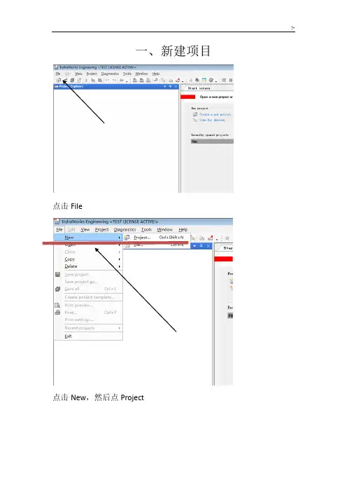
一、新建项目
点击File
点击New,然后点Project
这里
输入
选14V16 文件
名
都选完之后单机OK
二、组态设备
右键
Project
然后点击ADD
点击ADD
后,选
IndraMoti
on MLC,
之后选我
圈的这个
单机
NEXT
注意这个
IP地址一
定要改成
192.168.1.1
然后单击
NEXT
选LD,梯
形图,之
后点击
NEXT
一直点击NEXT,最后FINISH
右击
S20_I_O
后点击
ADD
点击S20-DI-16/1然后点ADD,用此方法依次添加S20-DI-16/1,S20-DO-8/2-2A,S20-AI16-AO2-SSI2,全部添加完毕后点Close
双击打开
点开后选+/-10V,然后那Analog
Output2-Outputrange改为+/-10A
双击打开Library
Manager
点击Add library添加
库文件
在上面输入
RAMP_INT,然后点
击RAMP_INT点击
OK
双击PlcProg
(PRG)进入编程
页面
三、plc编程
一般指令所有PLC都一样,我在这里就介绍下这个PLC与别的PLC不同的。
1、PLC的计时器与计数器地址不用自己写,系统自动分配,只需要注意地址不重复。
2、关于中间变量,可以选择分配M区或者直接定义变量名,就可以使用。
3、上升沿下降沿,可以使用R-TRIG和N-TRIG,代替上升沿和下降沿也可以先插入一个常开触点,之后再右击Edge Detection,第一次切换为上升沿,第二次点击切换为下降沿,再次点击变回常开触点
4、斜坡
插入斜坡指令
插入空指令框
在线圈位置输入RAMP_INT
IN目标值ASCEND上坡时间DESCEND下坡时间TIMEBSASE斜坡时基RESET接通时OUT保持不变OUT为实际输出值。