德力西JS11系列时间继电器(新版)-说明书20170720(1)
- 格式:pdf
- 大小:3.75 MB
- 文档页数:1
三、技术特征3.1 额定绝缘电压Ui :AC380V3.2 额定冲击耐受电压Uimp :AC2.5kV 3.3 额定控制电源电压Us :见表13.4 使用类别下各个额定工作电压Ue /额定工作电流Ie :AC -15 Ue :AC380V ,Ie :0.95A ;Ue :AC240V ,Ie :1.5A ;Ue :AC120V ,Ie :3A ;DC -13 Ue :DC250V ,Ie :0.55A ;Ue :DC125V ,Ie :1.1A 3.5 约定发热电流Ith :5A3.6 触点容量:AC250V 3A ;(阻性);3.7 污染等级:33.8 整定误差:≤1%;3.9 重复误差:≤1%;3.10 机械寿命:≥100万次;3.11 电寿命:≥10万次;3.12 与短路保护器(SCPD )的协调配合:推荐使用SCPD 为RT16-00,6A 的熔断器,基本保护类型"1"型协调配合,即继电器在短路条件下不应对人及设备引起危害,在未修理或更换零件前,不允许继续使用。
在选用不同型号规格的熔断器保护器时,原有的协调配合可能失效。
一、概 述JS S 48 A -□/□额定控制电源电压Us:见表1规格代号:见表1数码管显示设计序号数字式时间继电器本时间继电器由外壳、设定面板、电子线路板和上插组成。
采用专用可编程数字集成电路,LED 发光数码管显示,数字按键开关预置,具有工作稳定可靠、精度高、延时范围宽、功耗低、外形美观、安装使用方便等优点。
1.1 适用范围执行标准:GB/T 14048.51.2 型号定义JSS48A -R 、2ZR 系列时间继电器,适用在交流50Hz /60Hz 和直流控制电路中,交流电压至220V 或直流电压至110V 的控制电路中作时间控制元件,按预定时间接通或分断电路。
是普通时间继电器升级产品,具有RS485接口,可实现与后台设备的通信,实现远程监控功能。

要求█ 关于工作环境:z 关于时间继电器的工作环境的温度、湿度。
请勿超过各产品的说明书上额定值z 存在贮存温度规定范围内的地方。
当在-10℃以下的地方贮存后使用,请先在常温下放置3小时以上然后再通电。
z 请不要多尘埃,腐蚀气体和直接日照的环境中使用z 当在有静电环境中使用时,时间继电器要离开静电发生源。
z 请注意时间继电器的外壳会被有机溶剂,强碱,强酸物质侵蚀█ 继电器使用情况:z 时间继电器内部的继电器在使用时请勿超过允许的电流电压。
否则会造成绝缘不良,接点融化,接触不良及继电器破损烧毁。
如果负载超过允许的电流电压,请使用中间继电器,接触器等。
z 时间继电器为非防爆型产品请勿在有易燃,易爆的气体场合使用。
继电器开关产生的电弧可能引发火灾和爆炸。
█ 无接点输出z 无接点输出请勿超过允许的电流电压,否则会造成短路等故障z 在使用直流感性负载时请使用续流二极管。
正确配线z 强电与弱电应分开配线,长度要短,弱电线请使用屏蔽导线,屏蔽网应接地。
因为如果把弱电线与电源线动力线,高压线配在同一管道或是绞合配线就会产生干扰,有可能产生误动作。
这是电子式时间继电器配线的最基本要求。
█在有变频器的场合虽然时间继电器内部已经有较强的抗干扰措施,但不当的配线仍然会影响时间继电器的正常工作,为保障时间继电器的工作稳定请采取以下措施z 变频器使用单独电源分路z 变频器与其他电器使用同一电源时请加装变频器用的滤波器或隔离变压器z 为防止辐射干扰请加装金属屏蔽z 时间继电器的弱电线应采用隔离屏蔽绞线,屏蔽网应正确接地,并远离变频器及其线路z 时间继电器0V 可接地。
接地线应尽量短电 源z 时间继电器电源必须使用继电器或开关迅速加入,不要电压缓慢上升的加入,或在加入电源时接点接触不稳定,不断的接通断开z 电压的波动范围必须符合时间继电器的电压要求。
负载与电寿命z 在额定的电压电流范围内使用。
时间继电器所标的电压电流均为最大值,时间继电器内部的控制继电器所标的电流为阻性负载时的最大电流,在使用感性负载或是灯电流时分别按30%,20%折算。
二、结构特征与工作原理光管状态指示,电磁继电器触点输出,具有工作稳定可靠、精度高、延时范围宽、功耗低、外形美观、体积小、安装使用方便等优点。
1.3 正常工作条件及安装条件1.3.1 使用环境:海拔高度不超过2000米;周围环境温度不高于+40℃及不低于-5℃;额定控制电源电压变化范围为85%-110%额定电压;在无严重震动和爆炸危险的介质中,且介质中无足以腐蚀金属和破坏绝缘的气体与尘埃;在雨雪侵袭不到的地方。
1.3.2 垂直或水平35mm 卡轨安装安装。
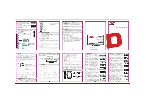
1.1 适用范围CDT18-JM 系列脉冲型时间继电器,适用于交流50/60Hz,电压380V及以下或直流240V的控制电路中作延时元件,按设定的时间接通或分断电路,起自动控制作用。
---主要用于延时并产生一个脉冲,用于给某个负载延迟接通一段时间。
具有单独的延时时间和脉冲宽度设定,可设置不同的延时时间。
执行标准:GB/T 14048.51.2 型号定义一、概 述3.1 额定绝缘电压Ui:AC380V3.2 额定冲击耐受电压Uimp:AC2.5kV3.3 额定控制电源电压Us:3.4 延时时间:延时3.6 使用类别下各个额定工作电压Ue/额定工作电流Ie:3.7 约定发热电流Ith:10A3.8 触点容量:AC250V 16A;(阻性);3.9 污染等级:33.10 整定误差:≤10%;3.11 重复误差:≤0.2%;3.12 温度波动误差:0.05%/℃at=20℃(0.05%℉,at=68℉)AC/DC12V 、AC220V 、、AC380V 、AC/DC24V~240V0.1s ~100d 3.5 延时方式:循环AC-15:Ue/Ie:AC240V/3A, AC380V/1.9A; DC-13:Ue/Ie:DC250V/1.1A, DC125V/2.2A;AC230V 三、技术参数电压变换器整流稳压LED 指示输出继电器MCU 单片机旋钮电位器设定工作原理方框图七、安装、使用操作说明3.13 机械寿命:≥100万次;3.14 电寿命:≥10万次;3.15 与短路保护器(SCPD )的协调配合:推荐使用SCPD 为RT16-00,10A 的熔断器,基本保护类型“1”型协调配合,即继电器在短路条件下不应对人及设备引起危害,在未修理或更换零件前,不允许继续使用。

Cast Current TransformerUser ManualStandard: GB/T 20840.1&2□Please carefully read this User Manual before installing and operating the product, and keep this manual properly for future referenceI. Overview1.1 LMZJ1-0.5, LMZJ1-0.66, LM Z3-0.66, and LM-0.5 series of current transformers are indoor devices, and they are used in the AC line with a rated frequency of 50Hz and a rated voltage 0.66kV and below for current, electric energy measurement and relay protection.1.2 Product standard: GB/T 20840.1&2II. Available Environment Conditions of Transformer2.1 The altitude at the installation site does not exceed 1000m;2.2 The ambient medium temperature is -5~+40°C;2.3 The relative humidity of air is not greater than 80%;2.4 Installed in a place where there is no dirt or aggressive and explosive medium that seriously affects the insulation of the transformer.III. Technical Parameters3.1 The meanings of the transformer model is described as follows:Rated voltage (kV)Design No.Large capacityCast insulationBusbar typeCurrent transformer3.2 Rated voltage: 0.5kV ~ 0.66kV;3.3 Rated frequency: 50Hz;3.4 Rated secondary current: 5A;3.5 Accuracy grade: Grade 1, Grade 0.5, Grade 0.2, Grade 0.5S, Grade 0.2S.3.6 Insulation requirements: The primary winding to the secondary winding and ground and the secondary winding to the ground can withstand a short-time power frequency withstand voltage of 3kV for one minute, and the insulation resistance is ≥ 100MQ.3.7 For current transformer with a load of 5VA or 10VA, the lower limit is 3.75VA, and the power factor is cosφ= 0.8 (except for customized products)IV. Key Components and StructureThe unsaturated resin is used in the transformer as main insulating material, the iron core is made of silicon steel sheet or amorphous crystalline material in the coiled way, and the secondary winding is wound with enameled round wire.V. Installation, Operation and Maintenance5.1 The transformer can be installed vertically or horizontally;5.2 The copper section of the connection line connected to the secondary instrument and relay is not less than 2.5mm2, and the secondary terminal is marked with S1 and S2. When the current flows from P1 to the P2 end, the secondary current flows to the S2 from S1 through the external circuit, and the transformer is in the subtractive polarity state;5.3 When the primary winding is powered with current, the open circuit of the secondary winding is strictly prohibited to prevent high voltage;5.4 The transformer storage site shall be kept dry and well ventilated, and the transformer shall be stored in the paper carton or wooden box for long-term storage; If the storage period of the product exceeds one year, the product shall be subject to the insulation resistance and power frequency withstand voltage test, and shall be dried if changed;5.5 The transformer shall be periodically verified, and any product failed to pass the verification shall be repaired or replaced.5.6 For bus type transformer, when it is used as a transformer with small transformation ratio, the window can be wound several times according to the data speci fied on the product nameplate to meet the user’s requirements. For details, see Table 1.VI. Outline and Installation DimensionsThe outline and installation dimensions of the transformer are illustrated in Table 2 and attached figures 1 ~ 10Fig. 1 (LMZ1-0.5 30-1200/5A) Fig. 2 (LM-0.5 30-600/5A)Fig. 3 (LMZJ1-0.5 750-3000/5A) Fig. 4 (LMZJ1-0.5 30-600/5A)Fig. 5 (LMZ1-0.66250-1200/5A) Fig. 6 (LMZJ1-0.66 150-2500/5A)Fig. 7 (LMZJ1-O.66 3000/5A) Fig. 8 (LMZJ1-0.66 type Grade 0.5, 120-50general assembly drawing) Fig. 9 (LMZ3-0.66 150-250/5A) Fig. 10 (LMZ3-0.66 300-2500/5A)Fig. 11 (LMZ3-0.66 3000/5A)H: High; W: Wide; D: Thickness; φd: Inner diameter;a: Window height; b: Window width;L1: Leg length; L2: installation width;VII. Company’s commitmentOur company will provide repair and replacement service free of charge for any damage or abnormal operation of the product due to poor manufacture quality within 24 months from the production date under the premise that users follow the use and storage conditions and the product are well sealed. A paid repair will be provided if the warranty period expires. For any damage due to one of the following situations, a paid repair will be given even if within the warranty period:(1)Improper operation, maintenance, or storage;(2)Modified and inappropriate repair without permission;(3)Damage due to falling off or during installation after purchase;(4)Force majeure such as earthquakes, fires, lightning strikes, abnormal voltages, and secondary disasters.If you have any question, please contact our dealer or our company’s customer service department.Customer service hotline:400-826-8008CertificateDELIXI GROUP CO., LTD.Manufacturer: Delixi Group Co., Ltd.Address: No. 155, Zhandong Road, Liushi Town, Yueqing City, Zhejiang P.C: 325604Tel: (86-577) 6177 8888Fax: (86-577) 6177 8000Customer Service Hotline: 400-826-8008。
![时间继电器js11s[1]](https://uimg.taocdn.com/57ca2629915f804d2b16c10f.webp)
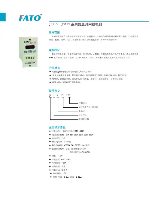
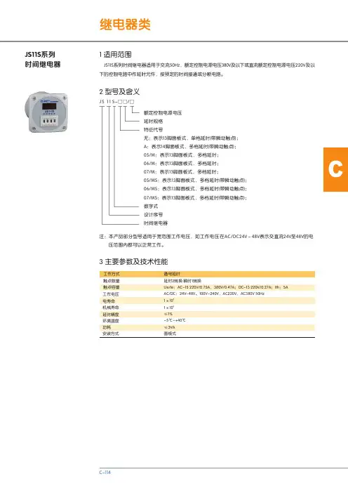
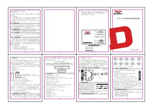
2 型号及含义JS11S系列时间继电器 JS11S系列时间继电器适用于交流50Hz,额定控制电源电压380V及以下或直流额定控制电源电压220V及以下的控制电路中作延时元件,按预定的时间接通或分断电路。
额定控制电源电压延时规格特征代号无:表示13脚面板式,单档延时(带瞬动触点);A:表示14脚面板式,多档延时(带瞬动触点);05/M:表示13脚面板式,多档延时;06/M:表示13脚面板式,多档延时;07/M:表示13脚面板式,多档延时;05/MS:表示13脚面板式,多档延时(带瞬动触点);06/MS:表示13脚面板式,多档延时(带瞬动触点);07/MS:表示13脚面板式,多档延时(带瞬动触点);数字式设计序号时间继电器注:本产品部分型号适用于宽范围工作电压,如工作电压在AC/DC24V~48V表示交直流24V至48V的电压范围内都可以正常工作。
1 适用范围J S 11 S-□□/□CAC/DC:24V~48V、100V240V,AC220V,AC380V 50Hz51×1061×10≤1%-5℃~+40℃≤3VA面板式~工作方式触点数量触点容量工作电压电寿命机械寿命延时精度环境温度功耗安装方式通电延时延时2转换 瞬时1转换3 主要参数及技术性能Ue/Ie:AC-15 220V/0.75A,380V/0.47A;DC-13 220V/0.27A;Ith:5A延时范围0.1s~9.9s,0.1s~99.9s,1s 99s,1s~999s,1s~9999s,1s~9min59s,1s~99min59s,~1min~99min,1min~999min,1min~9h59min,1min~99h59min,0.01s~99.99s 0.01s~99.99s,1s~99min99s,1min~99h99min 0.1s~99.9s,1s~999s 1s~999s,10s~9990s 10s~9990s,1min~999min型号JS11S JS11S-A JS11S-05/M(s)JS11S-06/M(s)JS11S-07/M(s)4 接线图5 外形及安装尺寸续上表C。
继电器的使用说明第一节继电器原理知识首先,继电器的定义是一种自动控制装置,当输入量(电、磁、声、光、热)达到一定值时,输出量会发生飞跃性的变化。
继电器是具有隔离功能的自动开关元件。
它广泛应用于遥控、遥测、通信、自动控制、机电一体化和电力电子设备。
它是最重要的控制元素之一。
.继电器通常具有感应机制(输入部件),可以反映某些输入变量(如电流、电压、功率、阻抗、频率、温度、压力、速度、光等)。
);有一个致动器(输出部分),可以控制受控电路的“开”和“关”;在继电器的输入部分和输出部分之间,还有一个连接和隔离输入量、处理功能和驱动输出部分的中间机构(驱动部分)。
作为控制元件,继电器具有以下功能:.1)扩大控制范围。
例如,当多触点继电器的控制信号达到一定值时,多电路可以根据触点组的不同形式同时接通、断开和接通。
.2)放大。
例如,灵敏继电器、中间继电器等。
可以用很小的控制量来控制大功率电路。
.3)集成信号。
例如,当多个控制信号以规定的形式输入到多绕组继电器时,通过比较和合成实现预定的控制效果。
4)自动、远程控制和监控。
例如,自动装置上的继电器与其他电器一起,可以形成程序控制电路来实现自动操作。
第二,继电器的工作原理如图所示。
当控制电路中的开关K闭合时,电磁铁将具有磁性,吸引衔铁使继电器触点接通,连接到触点的电源电路将接通。
当控制开关K关闭时,电磁铁的磁性被消除,继电器触点弹簧打开,电源电路也关闭。
第三,继电器的继电器特性当电枢开始拉入时,继电器的输入信号X从零连续增加到动作值xx,并且继电器的输出信号立即从y=0跳到y=ym,也就是说,常开触点从关到开。
一旦触点闭合,输入量x继续增加,并且输出信号y不会再次改变。
当输入值x从大于xx的值下降到xf时,继电器开始释放,常开触点断开(如图1所示)。
我们把继电器的这种特性称为继电器特性,也叫继电器输入——首先,继电器的定义是一种自动控制装置,当输入量(电、磁、声、光、热)达到一定值时,输出量会发生飞跃性的变化。
二、结构特征与工作原理数码管状态显示,电磁继电器触点输出,具有工作稳定可靠、精度高、延时范围宽、功耗低、外形美观、体积小、安装使用方便等优点。
1.3 正常工作条件及安装条件1.3.1 使用环境:海拔高度不超过2000米;周围环境温度不高于+40℃及不低于-5℃;额定控制电源电压变化范围为85%-110%额定电压;在无严重震动和爆炸危险的介质中,且介质中无足以腐蚀金属和破坏绝缘的气体与尘埃;在雨雪侵袭不到的地方。
1.3.2 垂直或水平35mm 卡轨安装安装。
1.1 适用范围CDT18-S 系列数显式时间继电器,适用于交流50/60Hz,电压380V及以下或直流240V的控制电路中作延时元件,按设定的时间接通或分断电路,起自动控制作用。
---可用于工业设备、照明控制、加热元件控制、马达、风机控制等。
具有20种延时模式,延时范围0.1秒~99天。
执行标准:GB/T 14048.51.2 型号定义一、概 述3.1 额定绝缘电压Ui:AC380V3.2 额定冲击耐受电压Uimp:AC2.5kV3.3 额定控制电源电压Us:3.4 延时时间:AC/DC12V 、AC220V 、、AC380V 、AC/DC24V~240V0.1s ~99d (24小时)3.5 延时方式:01通电延时、02延时断开、03循环延时(O FF 开始)、04循环延时(ON 开始)、05脉冲输出、06通过外部控制的通电延时、07延时断开(S 下降沿触发开始)、08延时断开(S 上升沿触发开始)、09 S 下降沿触发闭合,延时断开、10 接通/断开延时、11脉冲转换、12通过外部控制的循环延时(O FF 开始)、13通过外部控制的循环延时(On 开始)、14通过外部控制的脉冲输出、15通过外部控制的延时启动和停止、16通过外部控制的双延时断开、17通过外部控制延时启动、18通过外部控制延时闭合、19一直闭合、20一直断开AC230V 三、技术参数电压变换器整流稳压数码管显示输出继电器MCU 单片机按键开关设定工作原理方框图七、安装、使用操作说明四、产品外形、安装尺寸及接图线单位:(mm)(1) 因使用、维护、保管不当的;(2) 自行改装、不适当修理的;(3) 购买后由于摔落及安装过程中发生损坏的;(4) 地震、火灾、雷击、异常电压及二次灾害等不可抗力的;(5) 产品使用电寿命超过10万次;机械寿命超过100万次的。
二、结构特征与工作原理、精度高、延时范围宽、功耗低、外形美观、体积小、安装使用方便等优点。
1.3 正常工作条件及安装条件1.3.1 使用环境:海拔高度不超过2000米;周围环境温度不高于+40℃及不低于-5℃;额定控制电源电压变化范围为85%-110%额定电压;在无严重震动和爆炸危险的介质中,且介质中无足以腐蚀金属和破坏绝缘的气体与尘埃;在雨雪侵袭不到的地方。
1.3.2 垂直或水平35mm 卡轨安装安装。
1.1 适用范围CDT18-2T 系列双延时时间继电器,适用于交流50/60Hz,电压380V及以下或直流240V的控制电路中作延时元件,按设定的时间接通或分断电路,起自动控制作用。
---双延时时间继电器可设定2组通电延时时间,可用于重负 载分时投入,防止主回路电流峰值过大。
---特定场合可取代2只时间继电器,节省成本。
执行标准:GB/T 14048.51.2 型号定义一、概 述3.1 额定绝缘电压Ui:AC380V3.2 额定冲击耐受电压Uimp:AC2.5kV3.3 额定控制电源电压Us:3.4 延时时间:延时3.6 使用类别下各个额定工作电压Ue/额定工作电流Ie:3.7 约定发热电流Ith:10A3.8 触点容量:AC250V 16A;(阻性);3.9 污染等级:33.10 整定误差:≤10%;3.11 重复误差:≤0.2%;3.12 温度波动误差:0.05%/℃at=20℃(0.05%℉,at=68℉)3.13 机械寿命:≥100万次;AC/DC12V 、AC220V 、、AC380V 、AC/DC24V~240V0.1s ~10d 3.5 延时方式:通电AC-15:Ue/Ie:AC240V/3A, AC380V/1.9A; DC-13:Ue/Ie:DC250V/1.1A, DC125V/2.2A;AC230V 三、技术参数电压变换器整流稳压LED 指示输出继电器MCU 单片机旋钮电位器设定工作原理方框图七、安装、使用操作说明3.14 电寿命:≥10万次;3.15 与短路保护器(SCPD )的协调配合:推荐使用SCPD 为RT16-00,10A 的熔断器,基本保护类型“1”型协调配合,即继电器在短路条件下不应对人及设备引起危害,在未修理或更换零件前,不允许继续使用。