硼酸酯型汽车制动液的研制
- 格式:doc
- 大小:190.50 KB
- 文档页数:10
汽车制动液1.制动液的定义:汽车制动液又称刹车油,是用于汽车液压制动系统中传递压力的液体。
2.制动液的分类:汽车制动液一般分为如下3类:醇型、矿油型、合成型。
1)醇型制动液醇型制动液的基本组成是蓖麻油45%~55%和醇55%~45(百分数指质量分数)进行调配,产品润滑性好,原料易得,低温粘度大,工艺简单,但低温性能差,平衡回流沸点低,易产生气阻,与水互溶性差,使用过程中易氧化变质,不能保证安全行车。
2)矿油型制动液矿油制动液是以精制的柴油馏分经深度脱腊后的组分做为基础油,加入增粘剂、抗氧化剂、防锈剂、染色剂等调合而成。
这类制动液的温度适应范围宽、低温性能好,对金属无腐蚀作用。
但不能与水及合成制动液混溶,进入少量水后在高温下水气化而产生气阻,影响制动效果,对天然橡胶有溶胀作用,必须使用耐油橡胶密封件。
3)合成型制动液合成型制动液是目前使用最多的制动液,可分为3类:醇醚型、酯型和硅型。
(1)醇醚型制动液由润滑剂、稀释剂和添加剂组成,常用的润滑剂有乙二醇、聚丙二醇、环氧乙烷加成物、环氧丙烷的聚合物等,常用的稀释剂有二甘醇醚、三甘醇醚,四甘醇醚等。
常用的添加剂有抗氧剂、抗腐蚀剂、防锈剂、抗磨剂、PH值调整剂等。
产品性能较为稳定,成本较低,用量最大。
其缺点是平衡回流沸点不大高,及湿性强,低温性能差,而且在湿热气候条件下使用时,制动器部件易锈蚀。
(2)酯型制动液其基础液为羧酸酯与硼酸酯,加入量(质量分数)大约为总量的20%~50%,常用的衡释剂为聚乙二醇的单烷基醚等,常用的添加剂有抗氧化剂、抗腐蚀剂、PH值调整剂等。
性能比前者有很大改善。
(3)硅型制动液一般为烷撑聚醚硅酸酯如聚烷撑乙二醇硅酸酯等,并加有橡胶抗溶胀剂和其他添加剂。
这类制动液性能较好,但价格昂贵。
现在我们用的一般都是合成型的制动液,具体型号在车辆的使用手册上面,在车的制动液加注口上面或旁边也会有明显的标注。
一定要按标注的型号购买和使用,不得随意提高或降低标准,因为涉及到和活塞皮碗的性能匹配问题。
有机碱作用于硼酸酯型制动液中的影响探究随着汽车性能不断提高和车辆制动系统结构的不断完善,对汽车制动液性能要求也越来越高。
本文分别介绍脂肪胺类二正丁胺、醇胺类二乙醇胺、酰胺类二甲基甲酰胺三类调节剂对硼酸酯型制动液各性能的影响。
关键字:醇醚硼酸酯制动液;有机碱;硼酸酯;醇醚0 前言以目前汽车行业的快速发展对制动液性能推到新高度,传统工艺的制动液已满足不了大多数车辆的使用要求。
汽车制动液可以按照其生产原料的不同分为三种类型:醇型、矿物油型和合成型制动液[1],合成硼酸酯型制动液是当前市场占有率较高的一类制动液,各项质量指标要求较醇型、矿物油型更加严苛。
其优越的性能表现在具有更高的干、湿平衡回流沸点,不易产生气阻而造成刹车滞后;更低的低温运动粘度,在温度低的环境下硼酸酯型制动液流动性具佳,避免行车制动过程中刹车失灵;对制动系统中各种金属配件的腐蚀性小,橡胶适应性强,处于整个制动系统中不会影响配件的正常工作;抗氧化性能优越,高温下合成硼酸酯型制动液难以被氧化,原有的基本性能不易发生改变;蒸发损失小,合成硼酸酯型制动液长时间处于行车制动工作状态下,高温蒸发量小保证了制动液长期工作下不需要频繁添加。
现以硼酸酯为主体,醇醚为稀释剂和各种添加剂调和而成的合成硼酸酯型制动液,满足以上优越性能还需进行原材料筛选实验,市场上现有的硼酸酯、醇醚、复合剂复配调和后的制动液,在其它指标合格的前提下PH值不达标,将在本文讨论筛选出合适的PH调节剂以满足合成硼酸酯型制动液各项质量指标。
1 试验部分1.1 试样实验所需材料有:(1)多丁醚硼酸酯、四乙二醇甲醚硼酸酯、三乙二醇甲醚硼酸酯;(2)四乙二醇甲醚、三乙二醇甲醚、二乙二醇甲醚;(3)聚醚、二甘醇;(4)复合剂;(5)二正丁胺、二乙醇胺、二甲基甲酰胺,除以上主要材料外还需辅助材料有蒸馏水、无水乙醇、PH缓冲溶液、0.1mol/L氢氧化钠溶液。
1.2 试验条件取上述材料中的多丁醚硼酸酯、四乙二醇甲醚硼酸酯、三乙二醇甲醚硼酸酯、四乙二醇甲醚、三乙二醇甲醚、二乙二醇甲醚、聚醚、二甘醇、复合剂依次测出其干、湿平衡回流沸点、-40℃低温运动粘度以及PH值这三项重要基本指标,筛选出质量指标较优的硼酸酯和醇醚稀释剂。
机动车制动液的选择和使⽤(最新整理)机动车制动液的选择和使⽤⼀、机动车制动液的作⽤:制动液是保证机动车制动系统稳定、灵敏操作和机动车⾏驶安全的重要物质,是机动车⽤特种液之⼀,其在制动系统中的作⽤表现在以下四个⽅⾯:1.传递能量作⽤:传递制动能量,驱动制动装置正常可靠的⼯作。
2.冷却降温作⽤:制动装置执⾏制动刹车时,摩擦零部件温度会迅速升⾼,制动液可在⼀定程度上起到冷却降温作⽤。
3.防锈防腐作⽤:制动系统的⾦属件在空⽓中很容易产⽣锈蚀,防腐蚀性能优良的制动液可以延缓⾦属件的锈蚀。
4.润滑作⽤:制动液可以对制动泵的运动部件起到润滑作⽤。
⼆、机动车制动液的性能:刹车泵⼀般装在较密封的车轮内,空⽓流动不好,在机动车⾼速⾏驶时使⽤刹车,制动液要承受很⾼的温度。
⾼温可能会使制动液汽化⽽产⽣⽓阻,使刹车失灵。
如果制动液⾼温时黏度太低,会造成机械磨损和泄露,在低温时黏度过⾼,会导致传动不良、刹车失灵,因此制动液要有合适的⾼低温黏度。
对制动液具备的性能要求如下:1.较⾼的沸点,较低的蒸发损失。
2.适宜的⾼低温黏度,良好的低温流动性和润滑性。
3.良好的混容性和橡胶适应性,制动液要与刹车系统中的各种⾦属零部件及橡胶密封件具有很好的相容性。
4.良好的热安定性、⽔解安定性和化学稳定性。
5.良好的润滑性和防腐蚀性。
三、机动车制动液的分类:机动车制动液⾃从20世纪30年代开始使⽤,其发展经历了3个品种类型:醇型、矿物油型、合成型。
1.醇型:醇型制动液的基本组成是蓖⿇油和醇类如甲醇、丁醇等。
该型制动液润滑性好,原料易得,⼯艺简单,较好的满⾜了早期机动车制动系统的要求,但因其存在低温性能差、⽔溶性差、平衡回流沸点低等⽅⾯的缺陷,不能满⾜现代机动车制动系统的需要逐渐被淘汰。
我国已经于1990年强制淘汰了该型制动液。
2.矿物油型:矿物油型制动液是以精致的柴油馏分经深度脱蜡后的成分为基础油,加⼊增粘剂、抗氧化剂、防锈剂等调和⽽成。
矿物油型制动液有⾼温质量稳定,低温流动性好,对⾦属⽆腐蚀作⽤,消耗少,经济效益好等优点。
SAE Technical Standards Board Rules provide that: “This report is published by SAE to advance the state of technical and engineering sciences. The use of this report is entirely voluntary, and its applicability and suitability for any particular use, including any patent infringement arising therefrom, is the sole responsibility of the user.”SAE reviews each technical report at least every five years at which time it may be reaffirmed, revised, or cancelled. SAE invites your written comments and suggestions.Copyright © 2003 SAE InternationalAll rights reserved. No part of this publication may be reproduced, stored in a retrieval system or transmitted, in any form or by any means, electronic, mechanical, photocopying,recording, or otherwise, without the prior written permission of SAE.TO PLACE A DOCUMENT ORDER:Tel: 877-606-7323 (inside USA and Canada)Tel: 724-776-4970 (outside USA)Fax: 724-776-0790Email: custsvc@SAE WEB ADDRESS: J1Borate Ester Based Brake Fluids1.Scope—This SAE Recommended Practice was prepared to provide engineers, designers, and manufacturersof motor vehicles with a set of minimum performance standards which covers the next level of performanceproperties above those of the present SAE J1703 brake fluid standard. These fluids are not intended for useunder arctic conditions or in braking systems requiring the use of mineral oil based hydraulic fluid.These fluids are designed for use in braking systems fitted with rubber cups and seals made from naturalrubber (NR), styrene-butadiene rubber (SBR), or a terpolymer of ethylene, propylene, and a diene (EPDM).These fluids are not designed to operate in a pumped or a clutch braking system, especially those hydraulicsystems requiring a mineral oil based fluid.2.References 2.1Applicable Publications—The following publications form a part of this specification to the extent specifiedherein. The latest issue of SAE publications shall apply.2.1.1SAE P UBLICATIONS —Available from SAE, 400 Commonwealth Drive, Warrendale, PA 15096-0001.SAE J527—Brazed Double Wall Low Carbon Steel TubingSAE J1703—Motor Vehicle Brake Fluid 2.1.2ASTM P UBLICATIONS —Available from ASTM, 100 Barr Harbor Drive, West Conshohocken, PA 19428-2959.ASTM D 91—Test Method for Precipitation Number of Lubricating OilsASTM D 395—T est Methods for Rubber Property—Compression SetASTM D 412—T est Methods for Rubber Properties in TensionASTM D 445—T est Method for Kinematic Viscosity of T ransparent and Opaque Liquids (and theCalculation of Dynamic Viscosity)ASTM D 664—T est Method for Neutralization Number of Potentiometric TitrationASTM D 746—T est Method for Brittleness Temperature of Plastics and Elastomers by ImpactASTM D 865—T est Method for Rubber—Deterioration by heating in Air (Test T ube Enclosure)ASTM D 1120—Method of Test for Boiling Point of Engine CoolantsASTM D 1209—Test Method for Color of Clear Liquids (Platinum-Cobalt Pigments)ASTM D 1364—Test Method for Water in Volatile Solvents (Fischer Reagent Titration Method)ASTM D 1415—Method of Test for International H ardness of Vulcanized Natural Rubber and SyntheticRubbersASTM D1613—T est Method for Acidity in Volatile Solvents and Chemical Intermediates Used in Paint, Varnish, Lacquer, and Related ProductsASTM D 2240—Method of T est for Indentation Hardness of Rubber and Plastics by Means of a Durometer ASTM D3182—Recommended Practice for Rubber-Materials, Equipment, and Procedures for Mixing Standard Compounds and Preparing Standard Vulcanized SheetsASTM D3185—Methods for Rubber-Evaluation of SBR (Styrene-Butadiene Rubber) including Mixtures with OilASTM E 1—Specification for ASTM ThermometersASTM E 145—Specification for Gravity-Convection and Forced-Ventilation Ovens2.2Related Publications—The following publications are provided for information purposes only and are not arequired part of this document.2.2.1ASTM P UBLICATIONS—Available from ASTM, 100 Barr Harbor Drive, West Conshohocken, PA 19428-2959.ASTM D 344—Method of Test for Relative Dry Hiding Power of PaintsASTM E 260—Standard Recommended Practice for General Gas Chromatography ProcedureASTM E 298—Evaluation of Benzoyl Peroxides3.Materials—The quality of the materials used shall be such that the resulting product will conform to therequirements of these specifications and ensure uniformity of performance.4.Requirements4.1Equilibrium Reflux Boiling Point (ERBP)—Brake fluid when tested by the procedure specified in5.1 shallhave an equilibrium reflux boiling point not less than 230 °C (446 °F).4.2Wet Equilibrium Reflux Boiling Point—Brake fluid when tested by the procedure specified in5.2 shall have awet equilibrium reflux boiling point not less than 155 °C (311 °F).4.3Viscosity—Brake fluid when tested by the procedure specified in5.3 shall have the following kinematicviscosities:4.3.1A T –40 °C (–40 °F)—Not more than 1800 mm2/s (1800 cSt)4.3.2A T 100 °C (212 °F)—Not less than 1.5 mm2/s (1.5 cSt)4.4pH Value—Brake fluid when tested by the procedure specified in5.4 shall have a pH value not less than 7.0and not more than 11.5.4.5Fluid Stability4.5.1H IGH-T EMPERATURE S TABILITY—When tested by the procedure specified in 5.5.1, the equilibrium refluxboiling point of the brake fluid shall not change by more than 5 °C (9 °F) increase or decrease.4.5.2C HEMICAL S TABILITY—When tested by the procedure specified in 5.5.2 the test fluid mixture shall show nochemical reversion as evidenced by a change in recorded temperature of more than 5 °C (9 °F) increase or decrease.-2-标准分享网 免费下载-3-4.6Corrosion—See T able 1.4.6.1D RY F LUID (AS RECEIVED )—Brake fluid, when tested by the procedure specified in5.6.1, shall not causecorrosion exceeding the limits shown in Table 1. The metal strip outside of the area where the strips are in contact shall neither be pitted nor roughened to an extent discernible to the naked eye, but staining or discoloration is permitted. The fluid at the end of the test shall show no jelling at 23 °C ± 5 °C (73.4 °F ±9°F). No crystalline-type deposit shall form and adhere to either the glass walls or the surface of the metal strips. The fluid shall not contain more than 0.10% sediment by volume.The rubber specimens at the end of the test shall show no disintegration, as evidenced by blisters or sloughing indicated by carbon black separation on the surface of the rubber cup.4.6.2B RAKE F LUID WITH WATER —The brake fluid containing water, when tested by the procedure specified in5.6.2,shall not cause corrosion exceeding the limits shown in Table 1. The metal strip outside of the area where the strips are in contact shall neither be pitted nor roughened to an extent discernible to the naked eye, but staining or discoloration is permitted. The fluid/water mixture at the end of the test shall show no jelling at 23°C ± 5 °C (73.4 °F ± 9 °F). No crystalline-type deposit shall form and adhere to either the glass walls or the surface of the metal strips. The fluid/water mixture shall not contain more than 0.10% sediment by volume. The fluid/water mixture shall have a pH of not less than 7.0 and not more than 11.5.The rubber test specimens at the end of the test shall show no disintegration, as evidenced by blisters or sloughing indicated by carbon black separation on the surface of the rubber cup. The hardness of the SBR cup shall not decrease by more than 15 IRHD and the hardness of the EPDM rubber specimen shall not decrease by more than 10 IRHD. The SBR rubber cup shall not decrease in volume and shall not increase in volume by more than 16%. The EPDM rubber specimen shall not decrease in volume and shall not increase in volume by more than 10%.4.7Fluidity and Appearance at Low Temperatures 4.7.1A T –40 °C (–40 °F)—When brake fluid is tested by the procedure specified in 5.7.1, the fluid shall show nostratification, sedimentation, or crystallization. Upon inversion of the sample bottle, the air bubble shall travel to the top of the fluid in not more than 10 s. Cloudiness is permissible, but on warming to room temperature 23 °C ± 5 °C (73.4 °F ± 9 °F), this fluid shall regain its original unformity, appearance, and clarity.4.7.2A T –50 °C (–58 °F)—When brake fluid is tested by the procedure specified in 5.7.2, the fluid shall show no stratification, sedimentation, or crystallization. Upon inversion of the sample bottle, the air bubble shall travel to the top of the fluid in not more than 35 s. Cloudiness is permissible, but on warming to room temperature 23 °C ± 5 °C (73.4 °F ± 9 °F), the fluid shall regain its original unformity, appearance , and clarity.TABLE 1—CORROSION TEST STRIPS AND WEIGHT CHANGESTest Strips (1)1.Obtainable from the Society of Automotive Engineers, 400 Common-wealth Drive, Warrendale, P A 15096-0001.RM Number Maximum PermissibleWeight Change(mg/cm 2 of surface area)Tinned Iron6A 0.2Steel70.2Aluminum80.1Cast Iron90.2Brass100.4Copper 110.44.8Water Tolerance4.8.1A T –40 °C (–40 °F)—When the humidified brake fluid is tested by the procedure specified in5.8.1, the blackcontrast lines on a hiding power chart shall be clearly discernible when viewed through the fluid in the centrifuge tube. The fluid shall show no stratification or sedimentation. Upon inversion of the centrifuge tube, the air bubble shall travel to the top of the fluid in not more than 10 s.4.8.2A T 60 °C (140 °F)—When brake fluid is tested by the procedure specified in5.8.2, the fluid shall show nostratification, and sedimentation shall not exceed 0.05% by volume after centrifuging when fluid is tested for qualification, or shall not exceed 0.15% by volume for a commercial packaged fluid.4.9Compatibility4.9.1A T –40 °C (–40 °F)—When brake fluid is tested by the procedure specified in5.9.1, the black contrast lineson a hiding power chart shall be clearly discernible when viewed through the fluid in the centrifuge tube. The fluid shall show no stratification or sedimentation.4.9.2A T 60 °C (140 °F)—When brake fluid is tested by the procedure specified in5.9.2, the fluid shall show nostratification, and sedimentation shall not exceed 0.05% by volume after centrifuging.4.10Resistance to Oxidation—When the humidified brake fluid is tested by the procedure specified in5.10, itshall not cause the metal strips outside the areas in contact with the tinfoil to be pitted or roughened to an extent discernible to the naked eye, but staining or discoloration is permitted. No more than a trace of gum shall be deposited on the test strips outside of the areas in contact with the tinfoil. The aluminum strips shall not change in mass by more than 0.05 mg/cm2 and the cast iron strips shall not change in mass by more than0.3 mg/cm2.4.11Effect on Rubber4.11.1Rubber brake cups (RM-3a) subjected to brake fluid as specified in5.11.1 shall show no increase inhardness, shall not decrease in hardness by more than 10 IRH D, and shall show no disintegration as evidenced by blisters or sloughing indicated by carbon black separation on the surface of the rubber cup.Volume increase shall not be less than 1% or greater than 16%.4.11.2Rubber brake cups (RM-3a) subjected to brake fluid as specified in5.11.2 shall show no increase inhardness, shall not decrease in hardness by more than 15 IRH D and shall show no disintegration as evidenced by blisters or sloughing indicated by carbon black separation on the surface of the rubber cup.Volume increase shall not be less than 1% or greater than 16%.4.11.3Rubber slab stock (RM-69) subjected to brake fluid, as specified in5.11.3, shall show no increase inhardness, shall not decrease in hardness by more than 10 IRH D, and shall show no disintegration as evidenced by blisters or sloughing indicated by carbon black separation on the surface of the test specimens.The test specimens shall not decrease in volume and the increase in volume shall not exceed 10%.4.11.4Rubber slab stock (RM-69) subjected to brake fluid, as specified in5.11.4, shall show no increase inhardness, shall not decrease in hardness by more than 15 IRH D, and shall show no disintegration as evidenced by blisters or sloughing indicated by carbon black separation on the surface of the test specimens.The test specimens shall not decrease in volume and the increase in volume shall not exceed 10%.-4-标准分享网 免费下载5.Test Procedures5.1Equilibrium Reflux Boiling Point—Determine the equilibrium reflux boiling point of the fluid by ASTM D 1120with the following exceptions:5.1.1 A PPARATUS5.1.1.1 4.4 Thermometer—ASTM E 1, 76 mm immersion, calibrated. Use ASTM 3C or 3F thermometer. Forfluids boiling below 300 °C, ASTM 2C or 2F thermometer may be used.5.1.1.2 4.5 Heat Source—Use a suitable variac-controlled 100 mL heating mantle designed to fit the flask, capableof supplying the heat required to conform to the specified heating and reflux rates. (Supplier: GLAS COL Apparatus Co., Terre Haute, IN. Serial number: 135464. 230 W, 135 V [max.])5.1.1.3Boiling Point Stones RM-755.1.1.4Preparation of Apparatus—6.4 Thoroughly clean and dry all glassware before use. Attach the flask to thecondenser. Place the mantle under the flask and support it with a suitable ring clamp and laboratory-type stand, holding the whole assembly in place by a clamp.NOTE—Place the whole assembly in an area free from drafts or other types of sudden temperature changes.5.1.2P ROCEDURE—7.1 When everything is in readiness, turn on the condenser water and apply heat to the flask atsuch a rate that the fluid is refluxing in 10 min ± 2 min at a rate in excess of 1 drop/s. Immediately adjust heat input to obtain a specified equilibrium reflux rate of 1 to 2 drops/s over the next 5 min ± 2 min period.Maintain a timed and constant equilibrium reflux rate of 1 to 2 drops/s for an additional 2 min; record the average value of four temperature readings taken at 30 s intervals as the equilibrium reflux boiling point.5.1.2.1Report the boiling point to the nearest degree Celsius. Duplicate runs which agree within 3 °C areacceptable for averaging (95% confidence level).5.2Wet Equilibrium Reflux Boiling Point—Humidify the fluid and determine the boiling point.5.2.1H UMIDIFICATION P ROCEDURE—Lubricate the ground-glass joint of a 250 mm ID bowl-form desiccator havingmatched tubulated glass cover and fitted with a No. 8 rubber stopper. Pour 450 mL ± 10 mL of distilled water into the dessicator and insert a perforated porcelain plate (Coors No. 60456 or equivalent). Immediately place one open RM-49 corrosion test jar containing 350 mL ± 5 mL of the test brake fluid into the dessicator.Place a second open RM-49 corrosion test jar containing 350 mL ± 5 mL of TEGME (triethylene glycol monomethyl ether, brake fluid grade - Appendix E) (RM-71) into the same desiccator. The water content of the TEGME control fluid at the start of exposure shall have been adjusted to 0.50% ± 0.05% by weight (Karl Fischer analysis or equivalent). Replace desiccator cover and insert at once into an ASTM E 145, Type II A, forced ventilation oven set at 50 °C ± 1 °C (122 °F ± 1.8 °F).Periodically, during oven humidification, remove the rubber stopper from the desiccator and, using a long needle hypodermic syringe, quickly sample the control fluid and determine its water content. When the water content of the control fluid has reached 3.70% ± 0.05% by weight, remove the dessicator from the oven and seal the test jar promptly using a screw-cap lid (RM-63). Allow the sealed jar to cool for 60 to 90 min at 23 °C ± 5 °C (73.4 °F ± 9 °F).5.2.2W ET E QUILIBRIUM R EFLUX B OILING P OINT—Humidify the fluid as described in 5.2.1 and determine the boilingpoint as described in 5.1.-5-5.3Viscosity—Determine the kinematic viscosity of the fluid by ASTM D 445.5.3.1Report the viscosity to the nearest mm2/s (centistoke). Duplicate runs which agree within 1.2% relative areacceptable for averaging (95% confidence level).5.4pH Value—Mix the fluid with an equal volume of an 50% ethanol/50% distilled water mixture neutralized to apH of 7. Determine the pH of the resulting solution electrometrically at 23 °C ± 5 °C (73.4 °F ± 9 °F) using a pH meter equipped with a calibrated full range (0 to 14) glass electrode and a calomel reference electrode, as specified in ASTM D 664.5.5Fluid Stability5.5.1H IGH T EMPERATURE S TABILITY—Heat a new sample of the original test brake fluid to a temperature of 185 °C± 2 °C (365 °F ± 3.6 °F) by the procedure specified in 5.1 and maintain at that temperature for 2 h. Then determine the boiling point of this brake fluid as specified in 5.1. The difference between this observed boiling point and that previously determined in 5.1 shall be considered as the change in boiling point of the brake fluid.5.5.2C HEMICAL S TABILITY—Mix 30 mL of brake fluid with 30 mL of SAE Compatibility Fluid described in AppendixB (RM-66-05). Determine the equilibrium reflux boiling point of this fluid mixture by use of the test apparatusspecified in 5.1, applying heat to the flask at such a rate that the fluid is refluxing in 10 min ± 2 min at a rate in excess of 1 drop/s. The reflux rate shall not exceed 5 drops/s. Record the maximum fluid temperature observed during the first minute after the fluid begins refluxing at a rate in excess of 1 drop/s. Over the next15 min ± 1 min, adjust and maintain the rate of reflux to 1 to 2 drops/s. Maintain a timed and constantequilibrium reflux rate of 1 to 2 drops/s for an additional 2 min; record the average value of four temperature readings taken at 30 s intervals as the final equilibrium reflux boiling point. Chemical reversion is evidenced by the decrease in temperature between the maximum fluid temperature recorded and the final equilibrium reflux boiling point.5.6Corrosion5.6.1D RY F LUID (AS RECEIVED)—Prepare two sets of strips from each of the metals listed in Table 1, each striphaving a surface area of 25 cm2 ± 5 cm2 (approximately 8 cm long, 1.3 cm wide, and not more than 0.6 cm thick). Drill a hole between 4 and 5 mm in diameter and about 6 mm from one end of each strip. With the exception of the tinned iron strips, clean the strips by abrading them on all surface areas with 320A (RM-29) or P400 waterproof carborundum paper and isopropanol or ethanol until all surface scratches, cuts, and pits are removed from the strips, using a new piece of carborundum paper for each different type of metal. Wash the strips, including the tinned iron, with isopropanol or ethanol and dry the strips with a clean lint-free cloth and place strips in a desiccator containing desiccant maintained at 23 °C ± 5 °C (73.4 °F ± 9 °F) for at least1 h.Handle the strips with clean forceps after polishing to avoid fingerprint contamination.Weigh each strip to the nearest 0.1 mg and assemble each set of strips on an uncoated steel bolt (RM-61) in the order tinned iron, steel, aluminum, cast iron, brass, and copper, so that the strips are in electrolytic contact. Bend the strips, other than cast iron, so that there is a separation of at least 3 mm between adjacent strips for a distance of about 6 cm from the free end of the strips. (Immerse strip assemblies in isopropanol or ethanol to eliminate fingerprints and then handle only with clean forceps.)Use two SBR cups (RM-3a) and two 25.4 mm x 25.4 mm (1 in x 1 in) EPDM rubber slab stock (RM-69) test specimens as described in Appendix C and Appendix D, respectively.-6-标准分享网 免费下载Obtain two straight-sided round glass jars, having a capacity of approximately 475 mL and inner dimensions of approximately 100 mm in height and 75 mm in diameter (RM-49). T o the RM-49 corrosion test jar, apply four wrappings of 19 mm (3/4 in) Teflon tape around the jar threads allowing a 3 mm (1/8 in) height above the top of the jar. Place one SBR cup (RM-3a) with lip edge facing up, in each of the two glass jars. Use only tinned steel lids vented with a hole 0.8 mm ± 0.1 mm in diameter (RM-64).Insert a metal strip assembly inside each cup with the bolted end in contact with the concavity of the cup and the free end extending upward in the jar. Place one EPDM rubber slab stock (RM-69) test specimen flat on the bottom of the test jar.Add 400 mL of fluid to cover the metal strip assembly in each jar. Tighten the lid and place the jars in an oven maintained at 100 °C ± 2 °C (212 °F ± 3.6 °F) for 120 h ± 2 h. Allow the jars to cool at 23 °C ± 5 °C(73.4 °F ± 9 °F) for 60 to 90 min. Immediately following the cooling period, remove the metal strips from thejars by use of a forceps, removing loose adhering sediment by agitation of the metal strip assembly in the fluid in the jar. Examine test strips and test jars for adhering crystalline deposit, disassemble the metal strips, removing adhering fluid by flushing with water, and clean individual strips by wiping with a cloth wetted with isopropanol or ethanol. Examine the strips for evidence of corrosion and pitting. Place strips in a desiccator containing a desiccant maintained at 23°C ± 5 °C (73.4 °F ± 9 °F) for at least 1 h. Weigh each strip to the nearest 0.1 mg.Determine the difference in weight of each metal strip and divide the difference by the total surface area of the metal strip measured in square centimeters. Average the measured quantities of the duplicates. In the event of a marginal pass on inspection, or of a failure in only one of the duplicates, another set of duplicate test samples shall be run. Both repeat samples must meet all the requirements of 4.6.Immediately following the cooling period, remove the rubber cups from the jars by use of a forceps, removing loose adhering sediment by agitation of the cup in the fluid in the jar.Rinse the rubber specimens in isopropanol or ethanol and air dry cups. Examine the rubber specimens for evidence of sloughing, blisters, and other forms of disintegration.Examine the fluid in the jars for jelling. Agitate the fluid in the jars to suspend and uniformly disperse sediment and transfer a 100 mL portion of this fluid to an ASTM cone-shaped centrifuge tube and determine percent sediment as described in 5.2 of ASTM D 91.Measure the pH value of the corrosion test fluid by the procedure specified in 5.4.5.6.2C ORROSION T EST ON B RAKE F LUID WITH W ATER—Same test procedure as 5.6.1 except the test is performedon a brake fluid containing 5% by volume water.Prepare two sets of strips from each of the metals listed in Table 1 (see Appendix A), each strip having a surface area of 25 cm2 ± 5 cm2 (approximately 8 cm long, 1.3 cm wide, and not more than 0.6 cm thick). Drilla hole between 4 and 5 mm in diameter and about 6 mm from one end of each strip. With the exception ofthe tinned iron strips, clean the strips by abrading them on all surface areas with 320A or P400 waterproof carborundum paper (RM-29) and isopropanol or ethanol until all surface scratches, cuts, and pits are removed from the strips, using a new piece of carborundum paper for each different type of metal. Wash the strips, including the tinned iron, with isopropanol or ethanol and dry the strips with a clean lint-free cloth and place strips in a desiccator containing desiccant maintained at 23 °C ± 5 °C (73.4 °F ± 9 °F) for at least 1 h.Handle the strips with clean forceps after polishing to avoid fingerprint contamination.-7-Weigh each strip to the nearest 0.1 mg and assemble each set of strips on an uncoated steel bolt (RM-61) in the order tinned iron, steel, aluminum, cast iron, brass, and copper, so that the strips are in electrolytic contact. Bend the strips, other than cast iron, so that there is a separation of at least 3 mm between adjacent strips for a distance of about 6 cm from the free end of the strips. (Immerse strip assemblies in isopropanol or ethanol to eliminate fingerprints and then handle only with clean forceps.)Use two SBR cups (RM-3a) and two 25.4 mm x 25.4 mm (1 in x 1 in) EPDM rubber slab stock (RM-69) test specimens as described in Appendix C and Appendix D, respectively.Determine the weight of the cups and rubber slab stock in air (m1) to the nearest 1 mg then determine the apparent weight of the cup and slab stock immersed in distilled water at room temperature (m2). Quickly dip each specimen in alcohol and then blot dry with filter paper free of lint and foreign matter. Measure the hardness of each specimen by the procedure specified in ASTM D 1415 using the Standards Tester.NOTE—ASTM D 2240 may be used for quality control and routine tests when a type A durometer is equipped with a fixture for keeping the plane of the pressure foot on the durometer parallel to the plane of the cup face during measurement.Obtain two straight-sided round glass jars, having a capacity of approximately 475 mL and inner dimensions of approximately 100 mm in height and 75 mm in diameter (RM-49). T o the RM-49 corrosion test jar, apply four wrappings of 19 mm (3/4 in) Teflon tape around the jar threads allowing a 3 mm (1/8 in) height above the top of the jar. Place one SBR cup (RM-3a) with lip edge facing up, in each of the two glass jars. Use only tinned steel lids vented with a hole 0.8 mm ± 0.1 mm in diameter (RM-64).Insert a metal strip assembly inside each cup with the bolted end in contact with the concavity of the cup and the free end extending upward in the jar. Place one EPDM rubber slab stock (RM-69) test specimen flat on the bottom of the test jar.Mix 760 mL of fluid with 40 mL of distilled water.Add 400 mL of the mixture to cover the metal strip assembly in each jar. Tighten the lid and place the jars in an oven maintained at 100 °C ± 2 °C (212 °F ± 3.6 °F) for 120 h ± 2 h. Allow the jars to cool at 23 °C ± 5 °C (73.4 °F ± 9 °F) for 60 to 90 min. Immediately following the cooling period, remove the metal strips from the jars by use of a forceps, removing loose adhering sediment by agitation of the metal strip assembly in the fluid in the jar. Examine test strips and test jars for adhering crystalline deposit, disassemble the metal strips, removing adhering fluid by flushing with water, and clean individual strips by wiping with a cloth wetted with isopropanol or ethanol. Examine the strips for evidence of corrosion and pitting. Place strips in a desiccator containing a desiccant maintained at 23 °C ± 5 °C (73.4 °F ± 9 °F) for at least 1 h. Weigh each strip to the nearest 0.1 mg.Determine the difference in weight of each metal strip and divide the difference by the total surface area of the metal strip measured in square centimeters. Average the measured quantities of the duplicates. In the event of a marginal pass on inspection, or of a failure in only one of the duplicates, another set of duplicate test samples shall be run. Both repeat samples must meet all the requirements of 4.6.Immediately following the cooling period, remove the rubber cups from the jars by use of a forceps, removing loose adhering sediment by agitation of the cup in the fluid in the jar.Rinse the rubber specimens in isopropanol or ethanol and air dry cups. Examine the rubber specimens for evidence of sloughing, blisters, and other forms of disintegration.Within 15 min after removal from the fluid, weigh each specimen in air (m3), again to the nearest milligram, then reweigh immersed in room temperature distilled water (m4) to determine the volume change after hot fluid immersion.-8-标准分享网 免费下载。
2-甲基-1,3-丙二醇双环有机硼酸酯的合成及表征高鹏杰;梁淑琴;于秀丽;毛桢东;李惠萍【摘要】以2-甲基-1,3-丙二醇(MPO)和硼酸为主要原料,改进型铝酸盐为非酸催化剂,一锅法合成了新型双环有机硼酸酯2,2'-(2-甲基三亚甲基二氧基)双[5-甲基-1,3,2-二氧杂硼烷](简称MPO双环有机硼酸酯),经正交实验和单因素实验筛选,得到最佳工艺条件:n(MPO)/n(硼酸)=1.4∶1,催化剂/总物料=0.1%,甲苯/MPO=30%(V/V),反应温度220℃,收率可达95.3%,产物结构经IR,13C NMR和1H NMR确证.合成的双环硼酸酯具有强水解稳定性(120 h),该合成方法采用非酸催化,具有操作简便、产率高等特点.【期刊名称】《应用化工》【年(卷),期】2016(045)006【总页数】4页(P1070-1072,1077)【关键词】2-甲基-1,3-丙二醇(MPO);非酸催化剂;双环有机硼酸酯;结构表征;水解稳定性【作者】高鹏杰;梁淑琴;于秀丽;毛桢东;李惠萍【作者单位】郑州大学化工与能源学院,河南郑州 450001;郑州大学化工与能源学院,河南郑州 450001;郑州大学化工与能源学院,河南郑州 450001;郑州大学化工与能源学院,河南郑州 450001;郑州大学化工与能源学院,河南郑州 450001【正文语种】中文【中图分类】TQ341.22硼酸酯类化合物属于特种表面活性剂,具有无毒无臭、环境适应性好和极佳的抗磨减摩特性[1-2],在表面活性剂[3-4]、偶联剂[5-6]、汽车制动液[7]等方面均有广泛的应用,因而它的合成与性能研究一直受到人们的重视。
鉴于一锅法合成环状硼酸酯的可行性[8],本研究以2-甲基-1,3-丙二醇(MPO)和硼酸为主要原料,酯化合成了一种新型双环有机硼酸酯2,2’-(2-甲基三亚甲基二氧基)双(5-甲基-1,3,2-二氧杂硼烷)(简称MPO双环有机硼酸酯),考察了其水解稳定性。
pd催化硼酸酯制备
PD催化硼酸酯的制备方法如下:
材料:
1.苯甲醇
2.硼酸
3.苯甲酸
4.氯化钠
5.氯化苄基镁
操作步骤:
1.准备苄基镁试剂,将氯化苄基镁和苯甲醇在干燥的惰性气体下反应制备得到。
2.在反应瓶中加入苯甲酸和硼酸,搅拌均匀。
3.将苯甲醇逐渐滴加到反应瓶中,同时加入一定量的氯化钠,并加入苄基镁试剂,加入PD催化剂进行催化反应。
4.反应结束后,将反应溶液过滤并进行蒸汽蒸馏,得到硼酸酯产物。
注意事项:
1.一定要保持反应环境干燥无水,避免水分的干扰。
2.加PD催化剂后反应温度应控制在60℃左右,否则会影响反应的产率和选择性。
3.反应过程中需要不断搅拌,以保证试剂充分反应。
![基于正丁基锂制备硼酸酯的方法[发明专利]](https://uimg.taocdn.com/8ccff6c59f3143323968011ca300a6c30c22f1a3.webp)
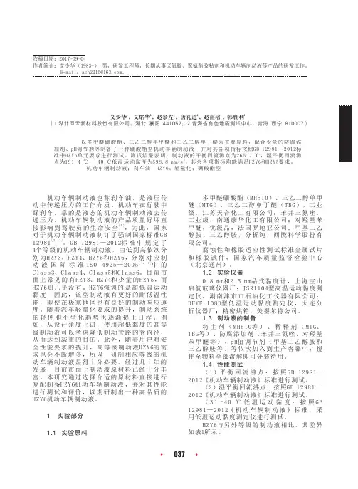
(19)中华人民共和国国家知识产权局(12)发明专利申请(10)申请公布号 (43)申请公布日 (21)申请号 201811521227.5(22)申请日 2018.12.12(71)申请人 苏州大学地址 215137 江苏省苏州市相城区济学路8号(72)发明人 薛明强 徐晓娟 颜丹丹 郑煜 武振杰 沈琪 (74)专利代理机构 苏州创元专利商标事务所有限公司 32103代理人 孙周强 陶海锋(51)Int.Cl.C07F 5/04(2006.01)(54)发明名称基于正丁基锂制备硼酸酯的方法(57)摘要本发明涉及正丁基锂的应用,具体涉及基于正丁基锂制备硼酸酯的方法。
依次将催化剂、硼烷和羧酸搅拌混合均匀,反应40~50分钟,暴露于空气中终止反应,反应液减压除去溶剂,得到不同取代基的硼酸酯。
本发明公开的正丁基锂可以在室温条件下高活性的催化羧酸和硼烷的硼氢化反应,催化剂用量仅为羧酸摩尔量的0.5mol%,与已有的催化体系相比,利用了商业化试剂正丁基锂,反应条件温和,在限定条件下不同取代基的硼酸酯的产率可达99%。
权利要求书1页 说明书6页CN 109438493 A 2019.03.08C N 109438493A1.基于正丁基锂制备硼酸酯的方法,包括以下步骤,在惰性气体氛围下,将硼烷和芳香族羧酸混合,再加入催化剂正丁基锂,然后进行硼氢化反应得到硼酸酯。
2.根据权利要求1所述基于正丁基锂制备硼酸酯的方法,其特征在于,所述硼烷为频哪醇硼烷。
3. 根据权利要求1所述基于正丁基锂制备硼酸酯的方法,其特征在于,所述芳香族羧酸和硼烷的用量摩尔比为 1:3~1:7。
4.根据权利要求1所述基于正丁基锂制备硼酸酯的方法,其特征在于,所述硼氢化反应的温度为室温。
5.根据权利要求1所述基于正丁基锂制备硼酸酯的方法,其特征在于,硼氢化反应结束后,接触空气中止反应,反应液减压除去溶剂,得到不同取代的硼酸酯。
6.根据权利要求1所述基于正丁基锂制备硼酸酯的方法,其特征在于,所述芳香族羧酸为苯甲酸、4-溴苯甲酸、4-氟苯甲酸、1-萘甲酸、2-甲氧基苯甲酸、邻羧基苯乙酸、3-吲哚乙酸、2-苯基丁酸、2-甲基-5-溴-苯甲酸、4-叔丁基苯甲酸、2-溴苯甲酸、4-碘苯甲酸、3-苯丙酸或者二苯基乙酸。
硼酸酯型润滑油添加剂的研究进展丛玉凤;纪灵娴;王德;陈鹏;黄玮【摘要】简要地阐述了硼酸酯润滑添加剂的发展现状和国内外研究动态。
将硼酸酯按分子中所含活性元素及主要官能团的种类进行了分类,并对其几种制备方法进行了总结,重点对其性能和作用机理的研究进行了分析和归纳,展望了其发展前景。
%The research situation and tendency of boric acid ester as lubricant additive at home and abroad were reviewed. Borate esters were classified according to active element and main functional group in borate ester molecule, and some preparation methods were summarized. Antiwear and extreme-pressure mechanism of boron-containing lubricant additives were researched emphatically, and its development prospect was descussed.【期刊名称】《当代化工》【年(卷),期】2013(000)002【总页数】4页(P181-183,186)【关键词】硼酸酯;极压抗磨;润滑;添加剂【作者】丛玉凤;纪灵娴;王德;陈鹏;黄玮【作者单位】辽宁石油化工大学化学与材料科学学院,辽宁抚顺 113001;辽宁石油化工大学化学与材料科学学院,辽宁抚顺 113001;辽宁石油化工大学化学与材料科学学院,辽宁抚顺 113001;辽宁石油化工大学化学与材料科学学院,辽宁抚顺 113001;辽宁石油化工大学化学与材料科学学院,辽宁抚顺 113001【正文语种】中文【中图分类】TE624每年世界上大约有三分之一的能源消耗在摩擦上,因此润滑油的使用必不可少,而通过向润滑油中添加性能优良的润滑剂可以减少摩擦和磨损,提高机械效率,减少能源消耗,延长机械寿命[1]。
硼酸酯型汽车制动液的研制摘要:本作品研制出一种水解稳定性好的硼酸酯,并开发了一种以此硼酸酯为主体,含有润滑剂、稀释剂和添加剂的硼酸酯型制动液的生产工艺。
通过制动液的性能分析,表明所研制的制动液达到美国联邦机动车辆安全标准FMVSSNO.116DOT-5 的要求,为一新型高级合成制动液。
关键字:硼酸酯合成制动液添加剂硼酸酯型汽车制动液的研制前言:汽车制动液是液压式汽车制动系统中使用的传递制动能量的功能液体,其质量性能状况直接关系到车辆的行驶安全。
我国长期以来一直沿用的是质量低劣的醇醚型制动液,它的价格虽然低廉,但沸点低,易在刹车过程中因磨攘生热而产生高温气阻,致使刹车失灵,低温时粘度大,寒冷地区无法使用,每年因制动液而发生的交通事故屡见不鲜。
因此研制生产高等级合成制动液显得尤为重要。
自从20世纪30年代汽车开始使用制动液以来,制动液的发展经历了3个品种类型,即蓖麻油醇型制动液、矿物油型制动液和合成型制动液。
蓖麻油醇型制动液是汽车最初使用的制动液,因其平衡回流沸点只有80℃。
高、低温性能差,在高温条件下使用易产生气阻,在低温下使用易发生制动迟缓而导致刹车失灵]1[。
因此,美国早在30年代就淘汰了醇型制动液为了克服醇型制动液的缺点,又对矿物油型制动液进行了研究。
矿物油型制动液的优点是:高、低温性能好,不易产生气阻或低温制动失灵;防锈性能好,不腐蚀金属;润滑性能好,制动灵活但其缺点也很明显:该产品对天然橡胶皮碗适应性差,容易胀裂而发生事故;与水分不相容,少量水进入后,在高温条件下容易汽化产生气阻,可导致刹车故障。
因此,我国和其他许多国家已不再使用矿物油型制动液。
鉴于醇型和矿物油型制动液产品存在性能上的缺陷,合成制动液应运而生,国内外开展了大量研究工作。
目前,合成制动液主有3类,即醇醚型、酯型和硅油型。
其中,酯型制动液又分为羧酸酯型和硼酸酯型制动液;硅油型制动液分硅酮型和硅酯型制动液]2[。
在合成制动液中,醇醚型DOT5、SA.E J1703制动液属于中、低级产品;酯型DOT4、SA.E J1704、超级DOT4制动液属于中、高级产品;硼酸酯型DOT5和硅油型制动液属高级产品。
本作品根据国内外合成制动液现状以及发展趋势,制备质量等级较高的硼酸酯型合成制动液。
一般制动液的性能应满足高沸点、低挥发性,夏天高温时不易产生气阻;适当的低温粘度性能,在寒冷的地区能保证其低温流动性;良好的防腐蚀性能,对任何金属无腐蚀和锈蚀作用;对橡胶皮碗不溶胀、不收缩;好的化学稳定性、抗氧化性及热稳定性。
此外,随着汽车的材质、类型、使用方式和气候条件的不同,还要求汽车制动液具备其他的一些性能。
而硼酸酯型制动液除了具有以上特点外,还具有环保、无毒、平衡回流沸点高,较低的低温粘度,良好的橡胶胶适应性能和对金属零部件腐蚀性较低等等优点。
同时和醇醚型制动液具有较好的相容性。
1实验部分1.1仪器与材料真空泵,Y 型管,分流柱,恒温干燥箱,抽滤瓶,圆底单口烧瓶,分液漏斗,布氏漏斗,电磁搅拌器,粘度计(内径0.6mm ),温度计,电加热套,干湿沸点测定仪,酸度计,电子天平,恒温干燥箱,电磁搅拌器,干燥器等。
乙二醇,硼酸,双酚A ,三乙二醇单丁醚,三乙二醇单甲醚,四乙二醇单甲醚,乙醇胺等。
1.2硼酸酯的合成硼酸酯的合成装置见图1。
a —温度计;b —冷凝器进水口;c —冷凝器出水口;d —羊角管(连真空装置);e —圆底烧瓶(接收反应中产生的水);f —反应烧瓶;g —分馏头图1合成反应装置图 取多聚乙二醇醚加入适量的硼酸酯于圆底烧瓶(f )内,加入磁子开启搅拌器,加热至80~120℃,使物料发生酯化反应。
酯化时使系统减压(真e空度为1300~8000Pa)以除去酯化生成的水及低分子量组分。
当系统残余水量小于0.2%时(温度在控制范围内,冷凝管不再有馏分析出),即为酯化终点。
最后得到酯化产品。
]18[1.3硼酸酯水解稳定性的测定方法硼酸酯的水解稳定性测定方法:将一杯蒸馏水在干燥器中放置8h以上,使干燥器保持水蒸气饱和环境,将约5g硼酸酯加入称量瓶中,尽快将试样放入干燥器中,观察液体开始变浑浊或出现沉淀的时间,以此时间做为判断硼酸酯水解稳定性的指标,实验温度为室温。
1.4制动液的制备在制动液的制备过程中,本实验分三步骤进行:第一步:控制添加剂的加入量不变,考察三个主要成分对制动液的平衡回流沸点,吸水性和运动粘度的影响,进而得出这三个性能都比较优良的配方。
第二步:以第一步中的出的优良配方为基础,保持三个主要成分配比不变,调节添加剂各组分的配比,从而使制动液的其他性能也得到优化。
第三部:在前两步的基础上,综合评价配方的性能,最终得出较优配方。
2结果与讨论2.1合成硼酸酯的IR图谱见图2。
350030002500200015001000500010203040506070透光率/%T 波数/cm -1图2 合成硼酸酯的IR 图谱(一)2.2制动液的性能分析分别进行制动液进行性能检验,采用金属叠片腐蚀检验方法评定制动液的高温性能,制动液蒸发损失检验法评定制动液的蒸发性能,制动液抗氧性检验法评定制动液的抗氧化特性,制动液橡胶皮碗适应性检验制动液及其原料对机动车辆液压制系统所用橡胶皮碗的适应性,制动液防锈性检验法评定制动液的防锈能力。
通过以上国标方法对制动液的性能进行表征,可以看出研制的制动液性能完全达到国标要求(附表一)的配方见表1,最终确定的配方见表2表1制动液配方的性能表征项 目 配方一 配方二外 观微黄;清澈透明;无沉淀。
微黄;清澈透明;无沉淀。
高温抗气阻性 干平衡回流沸点(℃) 240 233 湿平衡回流沸点(℃) 185 170运动黏度(mm2∕s)(-40℃)1300 1400 (50℃)748 835 (100℃)550 700橡胶皮碗实验根径%,120℃70h邵尔A下降2746 根径%70℃120h邵尔A下降4664金属腐蚀性质量变化(mg/cm2)镀锡铁皮+0.10 +0.11钢+0.11 +0.12铝-0.11 -0.09铸铁-0.10 -0.12黄铜-0.40 -0.41铜+0.32 +0.30PH值8 7.5蒸发率(100℃168h)(质量损失%)80 79(残余物倾点∕℃)-6 -8 残余物特征(手指捻摩)无颗粒无颗粒表2制动液配方组分名称合成硼酸酯/% 醇醚/% 多聚乙二醇/% 添加剂/%配方一23 62 13 2配方二16 65 17 23结论3.1硼酸酯的制备多聚醇醚硼酸酯的结构对于环状硼酸酯沸点的影响规律是:多聚醇醚链越长,其对应硼酸酯的沸点越低;对于链状硼酸酯的影响是:多聚醇醚链越长,其对应硼酸酯的沸点越高。
3.2制动液生产本作品考察了合成硼酸酯,多聚乙二醇醚和多聚乙二醇三大组分对制动液平衡回流沸点等性能的考察,并考察添加剂中的防腐剂,抗氧化剂等成分对制动液的各个性能的影响,最终得出硼酸酯型制动液的配方及生产工艺。
参考文献[1]刘自勇.汽车制动液[J].汽车维修技师,2009,(11):82.[2]张永斌,孙梅.制动液的品质要求与合理使用[J].农机使用与维修,2009(5):30[3]郭燕.有机硼酸酯应用现状及发展趋势[J].贵州化工,2009,34(2):26~28.[4]李洪波.机动车制动液的选择和使用[J].物探装备,2006,16(4):292~294.[5]李晓华,吴政清.制动液的全面认识及选用[J].润滑与密封,2004(2):87~88.[6]王洪武.正确选择和使用汽车制动液[J].汽车维护与修理,2008(1):59~60.[7]王海鹰,柴立元,史书阳,吕春绪.两组聚硼酸酯化合物的溶液缓蚀性能研究[J].日用化学工业,2009,39(5):301~304.[8]姜林.我国合成制动液的技术和质量状况[J].润滑油,2007,22(3):11~14.[9]赵晓晨,纪桂芬.国内外合成制动液的应用现状与发展趋势[J].炼油与化工,2008,19(14):7~8.[10]杨惠军,王成勇.解析新版ISO 4295:2005制动液国际标准[J].润滑油,2007,22(2):60~64.[11]李英奇,彭雨春.合成芳基硼酸及其酯的研究进展[J].化学试剂,2006,28(3):149~152.[12]傅俊红,胡丽天.咪唑啉硼酸酯的制备及其减摩抗磨机理研究[J].摩擦学学报,2007,27(1):29~34.[13]郑东东,刘志强.国内外汽车制动液的发展现状及趋势[J].润滑油,2009,24(4):1~4.[14]靳建平.ABS系统制动液的正确选用、更换及补充[J].实用汽车技术,2007(3):29.[15]王军,刘文彬,史爱峨.汽车用制动液、传动液及添加剂[M].北京:化学工业出版社,2006:118~121.[16]王海鹰,柴立元,吕春绪.新型聚硼酸酯的合成及其表面活性[J]石油化工,2009,38(8):884~887.[17]姚俊兵,润滑油脂抗磨极压添加剂研究进展[J].润滑油,2006,21(3):29~37.[18]张浩,涂政文,付尚发.含氮硼酸酯添加剂的合成及其摩擦学性能研究[J].润滑与密封,2008,33(8):94~97.[19]王海鹰,李斌栋,林卫娜,等.新型聚合硼酸酯表面活性剂PBE的合成及其性能[J].应用化学,2007,24(3):340~344.[20]Gtilsoy HO,Bilici M K,Bozkurt Y,et a1.Enhancing the wear properties of iron based powder metallurgy alloys by boron additions[J] .Mater Design,2007,28:2255~2259.[21]Levine JA,Wu S.Borate ester lubricant additives:EP,1625193[P].2006,(2):15.[22]Robinson Philipl,Blasser Janee.Method for treatingwoodUS2007087213[P] .2007,(4):19.[23]Jakle F.Lewis Acidic Organoboron Polym ers[J].Coord Chem Rev,2006,250:1107~1121.。