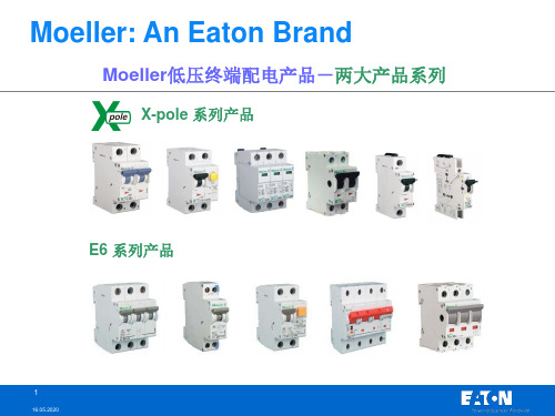
穆勒产品介绍---EASY电子式控制继电器
- 格式:ppt
- 大小:1.79 MB
- 文档页数:19

Eaton 197509Eaton Moeller® series EASY easyE4 control relay, basic unit (expandable, Ethernet), 100–240 VAC, 100–240 VDC (cULus: 100–110 VDC), digital inputs: 8, digital outputs: 4 relay, push-inSpécifications généralesEaton Moeller® series EASY Control relay197509401508194087558 mm 90 mm 72 mm 0.25 kg IEC/EN 61000-4-2 IEC 60068-2-27 IEC/EN 61000-4 EN 55011 EN 55022 IEC 60068-2-6 UL ListedUL Category Control No.: NRAQ, NRAQ7 IEC/EN 61131-2 IEC 60068-2-30 EN 61010 IEC/EN 61000-6-3 IEC/EN 61000-6-2 EN 50178UL File No.: E205091 DNV GL CEAccuracy of the real-time clock depending on ambient air temperature - fluctuations of up to ± 5 s/day (± 0.5 h ⁄year) are possibleEASY-E4-AC-12RCX1P Product NameCatalog Number EANProduct Length/Depth Product Height Product Width Product Weight Certifications Catalog NotesModel CodeExpandable Networkable (Ethernet)Relay outputTimerReal time clock IP2050/60 Hz (Digital inputs, at 115/230 V AC)50/60 Hz (Digital inputs, at 24 V DC)According to EN 50178, EN 61010-2-201, UL61010-2-201, CSA-C22.2 NO. 61010-2-20125,000 Operations (Fluorescent lamp load 1 x 58 W at 230/240 V AC, conventional, compensated)25,000 Operations (Fluorescent lamp load 10 x 58 W at 230/240 V AC, with upstream electrical device)25,000 Operations (Fluorescent lamp load 10 x 58 W at 230/240 V AC, uncompensated)25,000 Operations (Filament bulb load at 500 W, 115/120 V AC) 25,000 Operations (Filament bulb load at 1000 W, 230/240 V AC)1,000,000 OperationsTop-hat rail fixing (according to IEC/EN 60715, 35 mm)Screw fixing using fixing brackets ZB4-101-GF1 (accessories) Front build in possibleRail mounting possibleIII2Control relays easyE4MODBUSTCP/IP6 kV (contact-coil)5 % (transistor outputs)≤ 5 %Features Fitted with:Degree of protectionInput frequencyInsulation resistanceLifespan, electricalLifespan, mechanicalMounting methodOvervoltage categoryPollution degreeProduct categoryProtocolRated impulse withstand voltage (Uimp) Residual rippleEASYSOFT-SWLIC/easySoft70.5 Hz, Inductive load, Relay outputs 10 Hz, Relay outputs2 Hz, Resistive load/lamp load, Relay outputs easyE4 base device easyE4B 300 Light Pilot Duty, UL/CSA Control Circuit Rating Codes AC R 300 Light Pilot Duty, UL/CSA Control Circuit Rating Codes DC AC50 mm Drop height, Drop to IEC/EN 60068-2-310.3 mHorizontal Vertical15 g, Mechanical, according to IEC/EN 60068-2-27, Half-sinusoidal shock 11 ms, 18 Impacts According to IEC/EN 60068-2-6 10 - 57 Hz, 0.15 mm constant amplitude 57 - 150 Hz, 2 g constant acceleration795 - 1080 hPa (operation)-25 °C55 °C-40 °C70 °CClearance in air and creepage distances according to EN 50178, EN 61010-2-201, UL61010-2-201, CSA-C22.2 NO. 61010-2-201 Condensation: prevent with appropriate measures 5 - 95 % (IEC 60068-2-30, IEC 60068-2-78)ResolutionSoftwareSwitching frequencyTypeUsed with Utilization categoryVoltage type Drop and toppleHeight of fall (IEC/EN 60068-2-32) - max Mounting position Shock resistanceVibration resistanceAir pressureAmbient operating temperature - min Ambient operating temperature - max Ambient storage temperature - min Ambient storage temperature - max Environmental conditionsRelative humidityAir dischargeTerminal capacity1 min (Range H:M)1 s (Range M:S)5 ms (Range S)8 kV2 kV, Signal cable2 kV, Supply cableAccording to IEC/EN 61000-4-46 kV1 V/m at2 - 2.7 GHz (according to IEC EN 61000-4-3)10 V/m at 0.08 - 1.0 GHz (according to IEC EN 61000-4-3)3 V/m at 1.4 - 2 GHz (according to IEC EN 61000-4-3)10 V (according to IEC/EN 61000-4-6)Class B (EN 61000-6-3)1 kV, Supply cables, symmetrical, power pulses (Surge), EMC2 kV, Supply cables, asymmetrical, power pulses (Surge), EMC According to IEC/EN 61000-4-5 Level 410 ms 0.2 - 2.5 mm² (22 - 12 AWG), flexible with ferrule0.2 - 4 mm² (AWG 22 - 12), solid8 A4 W10 W200000 Operations at DC-13, 24 V DC, 1 A (500 Ops./h) 300000 Operations at AC-15, 250 V AC, 3 A (600 Ops./h)240 VMax. 300 V ACMax. 300 V DC85 - 264 V AC100/110/115/120/230/240 AC (-15 %/+10 %)50/60 Hz (± 5%)85 VAC264 VAC85 VDC264 VDC1 A DC, at R 300 (UL/CSA)10 A AC, at 240 V AC (UL/CSA)8 A DC, at 24 V DC (UL/CSA)5 A AC, max. thermal continuous current cos ϕ = 1 at B 300 (UL/CSA)Burst impulseContact dischargeElectromagnetic fieldsImmunity to line-conducted interference Radio interference classSurge ratingVoltage dips Conventional thermal current ith of auxiliary contacts (1-pole, open)Power consumptionPower lossRated breaking capacityRated insulation voltage (Ui)Rated operational voltageSupply frequencySupply voltage at AC, 50 Hz - minSupply voltage at AC, 50 Hz - maxSupply voltage at DC - minSupply voltage at DC - maxUninterrupted current≥ 1A (T), Fuse, Power supply Ethernet: RJ45 plug, 8-polePush in terminals10/100 MBit/sStatus indication of Power/RUNStatus indication of Ethernet: LED100 m (max. permissible per input I7 to I8), Digital inputs115/230 V AC40 m (max. permissible per input I1 to I6), Digital inputs 115/230 V ACCAT5± 2 s/day, Real-time clock to inputs (± 0.2 h⁄Year)± 1 %, Repetition accuracy of timing relays (of values)21 ms typ., Digital Inputs 100 - 240 V AC 60 Hz (I1 - I8), Delay time from 0 to 1, Debounce OFF21 ms typ., Digital Inputs 100 - 240 V AC 60 Hz (I1 - I8), Delay time from 1 to 0, Debounce OFF16⅔ ms, Digital inputs 115/230 V AC 60 Hz (I7, I8), Delay time from 1 to 0, Debounce OFF0.03 ms typ., Digital Inputs 100 - 240 V DC (I1 - I8), Delay time from 0 to 1, Debounce OFF0.03 ms typ., Digital Inputs 100 - 240 V DC (I1 - I8), Delay time from 1 to 0, Debounce OFF20 ms typ., Digital Inputs 100 - 240 V DC (I1 - I8), Delay time from 0 to 1, Debounce ON20 ms, Digital inputs 115/230 V AC 50 Hz (I7, I8), Delay time from 1 to 0, Debounce OFF20 ms typ., Digital Inputs 100 - 240 V DC (I1 - I8), Delay time from 1 to 0, Debounce ON2 x 6 mA (I7 - I8, at 230 V AC, 50 Hz, at signal 1)2 x 4 mA (I7 - I8, at 115 V AC, 60 Hz, at signal 1)6 x 0.25 mA (I1 - I8, at 115 V AC, 60 Hz, at signal 1)Condition 1: 79 - 264 V AC, Digital inputs, 115/230 V AC) Condition 0: 0 - 40 V AC, Digital inputs, 115/230 V AC)28/28 VA (DC, at R 300)3600/360 VA (AC, at B 300)Short-circuit protection Connection typeData transfer rateLED indicatorCable length Cable type AccuracyDelay timeInput currentInput voltageMaking/breaking capacity84VoltageRelay outputs in groups of 1> 500 mA (Relay outputs, Recommended for load: 12 V AC/DC) Current4 Relay OutputsNot permitted NoneBasic isolation: 600 V AC (Relay outputs)Between Analog inputs and Digital inputs: noBetween Relay outputs: yesBetween Digital inputs 115/230 V AC and Interface: yes Between Digital inputs 115/230 V AC and Memory card: noYesNone300 V AC, Between coil and contact, According to EN 50178 300 V AC, Between two contacts, According to EN 501784 W0 W0 W4 WMeets the product standard's requirements. Meets the product standard's requirements. Meets the product standard's requirements. Meets the product standard's requirements. Meets the product standard's requirements.eaton-electrical-timers-easy-control-relays-characteristic-curve-002.epsDA-DC-00004703.pdfDA-DC-00004708.pdfDA-CE-ETN.EASY-E4-AC-12RCX1PDA-MN-h1430deMN050009_FRMZ049014ENmz049001en.pdfVideo easy E4 control relayIL050020ZUDA-CD-uc_12rcx1DA-CS-uc_12rcx1Number of inputs (analog)Number of inputs (digital) Number of outputs (analog) Number of outputs (digital) OutputParallel switching Explosion safety category for gas Potential isolationProtection against polarity reversal Explosion safety category for dust Safe isolationEquipment heat dissipation, current-dependent PvidHeat dissipation capacity PdissHeat dissipation per pole, current-dependent PvidStatic heat dissipation, non-current-dependent Pvs10.2.2 Corrosion resistance10.2.3.1 Verification of thermal stability of enclosures10.2.3.2 Verification of resistance of insulating materials to normal heat10.2.3.3 Resist. of insul. mat. to abnormal heat/fire by internal elect. effects10.2.4 Resistance to ultra-violet (UV) radiation Characteristic curve Declarations of conformity eCAD modelGuide utilisateurInstallation videos Instructions d'installation mCAD modelDoes not apply, since the entire switchgear needs to be evaluated.Does not apply, since the entire switchgear needs to be evaluated.Meets the product standard's requirements.Meets the product standard's requirements.Meets the product standard's requirements.Does not apply, since the entire switchgear needs to be evaluated.Does not apply, since the entire switchgear needs to be evaluated.Is the panel builder's responsibility.Is the panel builder's responsibility.Is the panel builder's responsibility.Is the panel builder's responsibility.Is the panel builder's responsibility.The panel builder is responsible for the temperature rise calculation. Eaton will provide heat dissipation data for the devices.Is the panel builder's responsibility.Is the panel builder's responsibility.The device meets the requirements, provided the information in the instruction leaflet (IL) is observed.eaton-logic-relays-easy-control-relays-dimensions.eps 2723DIM-100eaton-modular-plc-easy-control-relays-3d-drawing-002.eps10.2.5 Lifting10.2.6 Mechanical impact10.2.7 Inscriptions10.3 Degree of protection of assemblies10.4 Clearances and creepage distances10.5 Protection against electric shock10.6 Incorporation of switching devices and components10.7 Internal electrical circuits and connections10.8 Connections for external conductors10.9.2 Power-frequency electric strength10.9.3 Impulse withstand voltage10.9.4 Testing of enclosures made of insulating material10.10 Temperature rise10.11 Short-circuit rating10.12 Electromagnetic compatibility10.13 Mechanical functionSchémasEaton Corporation plc Eaton House30 Pembroke Road Dublin 4, Ireland © 2023 Eaton. Tous droits réservés. Eaton is a registered trademark.All other trademarks areproperty of their respectiveowners./socialmedia。

超小型可编程序控制器easy的使用摘要:本文介绍了超小型可编程序控制器easy的主要资源、编程方法以及在中小型市政工程机械自动控制中的应用举例。
关键词:超小型可编程序控制器、编程示例、电机调速1 前目easy是德国穆勒(MOELLER)公司新推出的一种超小型可编程序控制器,也称控制继电器。
它可广泛应用在市政工程机械和水泥制品机械中,如商品混凝土搅拌站的自动控制,水泥制管机的调速控制等。
它小巧灵活,编程简单,性能价格比较高,适用于中小型设备。
与传统的可编程序控制器(PLC)相比,easy的突出优点是不需专用编程器。
easy面板自带编程按键和液晶显示屏,可以在面板上直接编程,使用非常方便。
easy有多种功能,如常规的继电器控制和时间继电器、计数器、实时时钟、定时器、脉冲信号发生器、掉电保持等。
有些型号的easy还有通信、文本显示、模拟量比较、扩展输入输出口等功能。
easy输出继电器的负载能力为:阻性负载8A,感性负载3A,可直接接交流接触器或电磁阀等小型负载。
easy基本型分为两个系列:easy 4系列主要特征为8路输入、4路输出;easy 6系列主要特征为12路输入、6路继电器或8路晶体管输出。
由于该器件问世不久,应用资料很少,译成中文的说明书又很简单。
本文以“easy619-AC-RC”为例,简要介绍easy的使用方法。
型号中AC表示电源及输入开关信号接交流110V~220V,R表示继电器输出,C表示带实时时钟。
文中所列程序,均经笔者验证。
2 easy 619的主要资源easy 619的主要资源见表1。
表1easy 619的接线图见图1。
图1注意:接线时接至easy输入端的均为常开触点。
原继电器控制电气原理图中的常闭触点可在easy编程时在开关符号处加上划线表示。
如easy的l号输人开关闭合,编程时11表示常开触点闭合,/1 1表示常闭触点断开(本文中“/I”即表示“i”,余类推)。
3.使用电路图编程easy的编程直接使用电路图,与常规的继电器控制原理图接近。

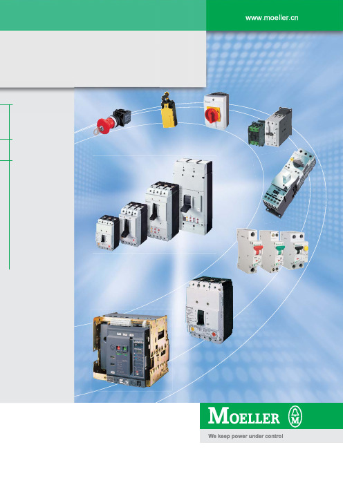
穆勒电气产品选型指南空气断路器和塑壳断路器围绕控制和显示的自动化产品、系统解决方案。
对机器设备高效地控制和显示。
穆勒电气工业自动化产品目 录空气断路器和塑壳断路器选型指南空气断路器IZM1,2,3空气断路器IZM58塑壳断路器NZM1-4E系列产品Xpole系列产品接触器和继电器电动机起动器按钮、指示灯凸轮开关和负荷隔离开关电子时间继电器限位开关控制继电器XI/ON模块低压终端配电产品选型指南工控产品选型指南2 - 15 页17 - 24 页26 - 33 页35 - 38 页40 - 47 页49 - 56 页57 - 59 页60 - 61 页62 - 64 页65 页65 - 67 页68 - 69 页70 页IZM1,2,3空气断路器型号含义X8: 可选的控制回路插接端X7: 可选的控制回路插接端X6: 标准的控制回路插接端X5: 可选的控制回路插接端远程复位XFR漏电互感器S2漏电互感器S1IZM-XW(C)N线互感器S2IZM-XW(C)N线互感器S1外部电压互感器公共端外部电压互感器L3外部电压互感器L2外部电压互感器L10VDC24VDC内部系统总线+内部系统总线-脱扣信号开关XHIA"储能弹簧已储能"信号XHIF电气合闸XEE第1个电压线圈脱扣信号开关第2个电压线圈脱扣信号开关第1个分励线圈XA标准辅助触点XHI-S1-"S"标准辅助触点XHI-S1-"B"合闸线圈XE"合闸准备就绪"辅助触点XHIB标准辅助触点XHI-S1-"S"标准辅助触点XHI-S1-"B"仅在XUV 作为"瞬时脱扣线圈"时使用端子13,14第二个电压线圈XE/A, XU, XUVXHI22: S3 "S"XHI22: S3 "B"XHI22: S4 "S"XHI22: S4 "B"可选的电机自动储能XM选择开关XMSIZM1,2,3 空气断路器控制回路端子分配图如果没有N极传感器采用短接端子输入UsUsUsUsUsUsIZM1,2,3 空气断路器脱扣单元-保护功能IZM1,2,3 空气断路器脱扣单元-保护功能注 1):若需数字型断路器的详细型号配置,请向Moeller 公司查询 IZM1,2,3空气断路器脱扣单元-功率、谐波测量,通讯功能,显示功能1) 注 1): 在IZM...-U...或IZM...-D...上选择测量、通讯功能、液晶显示器时,需同时配置24 VDC输入供电* 24 VDC输入接线端为X8.3与X8.4,请详见第30页接线端分配图**推荐使用 Moeller公司供电单元SN 4-050-B17,订货编号200034(输入:115V/230 V AC, 输出电压:24 - 3%V DC,输出电流:5A)2): 若需数字型断路器IZM...-D...的详细型号配置,请向 Moeller公司查询 IZM1,2,3空气断路器脱扣单元-功率、谐波测量,通讯功能,显示功能1) IZM1,2,3 空气断路器技术参数,框架1IZM1,2,3 断路器技术参数,框架1IZM1,2,3 空气断路器技术参数,框架2和3IZM1,2,3 空气断路器技术参数,框架2和3IZM1,2,3空气断路器接线图使用同一安装位置储能电机XM与电机自动储能选择开关XMS使用同一安装位置脱扣单元(含测量模块)说明:如果需要有关测量和通讯技术的进一步资料,请向MOELLER公司查询IZM58空气断路器选型指南空气断路器和塑壳断路器IZM58空气断路器保护&控制单元0.4-0.5-0.6-0.7-0.75-0.8-0.85-0.9-0.95-1.00.4-0.5-0.6-0.7-0.75-0.8-0.85-0.9-0.95-1.02.5 2.50.6-1.0-1.5-2-3-4-6-8-9-10(固定延时25ms)0.6-1.0-1.5-2-3-4-6-8-9-10I 2t OFF 20-100-200-300-400I 2t ON-20-100-200-300-400-OFF - 6-12-保护&控制单元 过载保护电流设置 (A), I r = I n x ... 延时, t r (s)于 6 x I r短路延时保护电流设置 (A), I sd = I n x ... 延时, t s (ms) 于10 x I n短路瞬时保护电流设置 (A), I i = I n x ... 热记忆LED 指示 电源接通 过载保护短路延时保护 短路瞬动保护 测试自诊断测试激活/阻止激活注 : 有此功能- 无此功能0.4-0.5-0.6-0.7-0.75-0.8-0.85-0.9-0.95-1.00.5-1-2-4-6-8-12-18-24-30OFF … 50% … 100%0.5-1-2-4-6-8-12-18-24-300.6-1.0-1.5-2-3-4-6-8-9-10I 2t OFF 20-100-200-300-400I 2t ON20-100-200-300-4001.5-2-3-4-5-6-8-10-12-MAX.24VDC0.4-0.5-0.6-0.7-0.75-0.8-0.85-0.9-0.95-1.00.5-1-2-4-6-8-12-18-24-30OFF … 50% … 100%0.5-1-2-4-6-8-12-18-24-300.6-1.0-1.5-2-3-4-6-8-9-1020-100-200-300-40020-100-200-300-4001.5-2-3-4-5-6-8-10-12-MAX.---保护&控制单元 过载保护电流设置 (A), I r = I n x ... 延时, t r (s) 于6 x I r 中性线过载保护电流设置 (A), I N = I r x ... 延时 (s)短路延时保护电流设置 (A), I sd = I n x ... 延时, t s (ms) 于10 x I n短路瞬时保护电流设置(A), I i = I n x ... 热记忆 LED 指示 电源接通 过载 短路 瞬动负荷百分比 单独的脱扣指示 过载短路/瞬动 辅助电源测试自诊断测试 注 有此功能 - 无此功能激活/阻止激活/阻止IZM58空气断路器保护&控制单元0.4-0.5-0.6-0.7-0.75-0.8-0.85-0.9-0.95-1.00.4-0.5-0.6-0.7-0.75-0.8-0.85-0.9-0.95-1.00.5-1-2-4-6-8-12-18-24-300.5-1-2-4-6-8-12-18-24-30OFF - 50% - 100%OFF - 50% - 100%0.5-1-2-4-6-8-12-18-24-300.5-1-2-4-6-8-12-18-24-300.6-1.0-1.5-2-3-4-6-8-9-100.6-1.0-1.5-2-3-4-6-8-9-10I 2t OFF 20-100-200-300-40020-100-200-300-400I 2t ON20-100-200-300-40020-100-200-300-4001.5-2-3-4-5-6-8-10-12-MAX. 1.5-2-3-4-5-6-8-10-12-MAX.0.2-0.3-0.4-0.5-0.60.2-0.3-0.4-0.5-0.6I 2t OFF 0.1-0.2-0.3-0.4-1.0-OFF 0.1-0.2-0.3-0.4-1.0-OFF I 2t ON0.1-0.2-0.3-0.40.1-0.2-0.3-0.4----24VDC激活/阻止激活/阻止保护&控制单元 过载保护电流设置 (A), I r = I n x ... 延时, t r (s) 于6 x I r 中性线过载保护电流设置 (A), I n = I r x ... 延时 (s)短路延时保护电流设置 (A), I sd = I n x ... 延时, t s (ms) 于10x I n短路瞬动保护电流设置(A), I i = I n x ... 接地保护电流设置 (A), I sd = I n x ... 延时, (s) tg热记忆 LED 指示 电源接通 过载 短路 瞬动接地故障 负荷百分比 单独的脱扣指示 过载短路/瞬动 接地故障 辅助电源 测试自诊断测试注 有此功能 - 无此功能IZM58空气断路器保护&控制单元负载L 1L 2L3脱扣器部分还可以安装以下两种脱扣器:IZM58空气断路器控制回路接线图IZM58空气断路器技术数据IZM58空气断路器技术数据最大空气断路器和塑壳断路器NZM1-4 塑壳断路器选型指南欠压线圈延时单元盒式端子防护盖电压 脱扣器数据管理界面数据插头通讯接口断路器端子盖相间隔板防护盖盒式端子盒式端子控制回路端子插拔式和抽屉式单元安装支架后部接线端子垫块脱扣指示辅助触点侧面操作手柄手柄锁定装置门联动旋转手柄用于柜体侧装的断路器旋转手柄旋转手柄延长杆远程操作机构绝缘柜外部警示牌NZM1-4塑壳断路器,隔离开关NZM1-4 塑壳断路器型号含义隔离开关型号说明NZM1-4 塑壳断路器脱扣器配置1. A(热磁脱扣器) 适用于NZM1,NZM2 断路器, 具有过载长延时保护和短路保护,整定值连续可调:过载长延时:I r = 0.8~1 x I n短路保护:I i = 6~10 x I n2. AE(电子脱扣器) 适用于NZM3,NZM4断路器,具有过载长延时,短路瞬时,整定值可调:过载长延时:I r = 0.5~1 x I n短路保护:I i = 2~11 x I n热记忆功能3. M(热磁脱扣器)电动机保护 适用于NZM1,NZM2 断路器,具有过载长延时保护和短路保护,整定值连续可调:过载长延时:I r = 0.8~1 x I n短路保护:I i = 8~14 x I n缺相保护4. VE(电子脱扣器)选择性保护 适用于NZM2, NZM3, NZM4断路器,整定值可调:过载长延时:I r = 0.5~1 x I n , Tr = 2~20s短路短延时保护:I sd = 2~10 x I n, T sd = 0~1000ms短路瞬时保护:I i = 2~12 x I n热记忆功能I2t可选5. ME(电子脱扣器)电动机保护 适用于NZM2,NZM3,NZM4断路器,整定值可调:过载长延时:I r = 0.5~1 x I n,Tr = 2~20s短路瞬时保护:I sd = 2~14 x I r热记忆功能缺相保护NZM1-4塑壳断路器主要参数表NZM1-4漏电保护器技术参数远程操作机构可以用于NZM 断路器 和 N 隔离开关,但不能用于 PN 隔离开关。

Eaton 198984Eaton Moeller® series Rapid Link - Speed controllers, 4.3 A, 1.5 kW, Sensor input 4, Actuator output 2, PROFINET, HAN Q4/2, with manual override switch, with braking resistanceGeneral specificationsEaton Moeller® series Rapid Link Speed controller1989844015081970421RASP5-4420PNT-412R100S1157 mm 270 mm 220 mm 3.62 kgIEC/EN 61800-5-1 UL 61800-5-1 CE RoHS UL approvalProduct NameCatalog NumberEANModel CodeProduct Length/Depth Product Height Product Width Product Weight Certifications Catalog Notes 3 fixed speeds and 1 potentiometer speedcan be switched over from U/f to (vector) speed control Connection of supply voltage via adapter480 VIs the panel builder's responsibility. The specifications for the switchgear must be observed.480 V AC, 3-phase400 V AC, 3-phaseMeets the product standard's requirements.1.5 kW500 VMeets the product standard's requirements.-40 °C380 VInternal DC linkControl unitBraking resistanceKey switch position OFF/RESETPTC thermistor monitoringBreaking resistanceIGBT inverterManual override switchKey switch position HANDSelector switch (Positions: REV - OFF - FWD)PC connectionTwo sensor inputs through M12 sockets (max. 150 mA) for quick stop and interlocked manual operation2 Actuator outputsKey switch position AUTOThermo-click with safe isolation0 Hz Generation Change RASP4 to RASP5Configuration to Rockwell PLC for Rapid LinkGeneration change from RA-SP to RASP 4.0Connecting drives to generator suppliesGeneration change from RA-MO to RAMO 4.0Generation change RAMO4 to RAMO5Electromagnetic compatibility (EMC)Generation Change RA-SP to RASP5Rapid Link 5 - brochureDA-SW-drivesConnect - installation helpDA-SW-Driver DX-CBL-PC-3M0DA-SW-drivesConnect - InstallationshilfeDA-SW-USB Driver PC Cable DX-CBL-PC-1M5DA-SW-drivesConnect USB Driver DX-COM-PCKITDA-SW-drivesConnectDA-SW-USB Driver DX-COM-STICK3-KITMaterial handling applications - airports, warehouses and intra-logisticsProduct Range Catalog Drives Engineering-ENProduct Range Catalog Drives EngineeringDA-DC-00004508.pdfDA-DC-00003964.pdfDA-DC-00004514.pdfDA-DC-00004184.pdfeaton-bus-adapter-rapidlink-speed-controller-dimensions-002.eps eaton-bus-adapter-rapidlink-speed-controller-dimensions-004.eps eaton-bus-adapter-rapidlink-speed-controller-dimensions-003.eps eaton-bus-adapter-rapidlink-speed-controller-dimensions-005.epsETN.RASP5-4420PNT-412R100S1.edzIL034093ZUMains voltage - max10.11 Short-circuit ratingRated operational voltage10.4 Clearances and creepage distancesOutput at quadratic load at rated output voltage - max Output voltage - max10.2.3.1 Verification of thermal stability of enclosures Ambient storage temperature - minMains voltage - minFitted with:Output frequency - min Application notes BrochuresCatalogs Certification reports DrawingseCAD model Installation instructions200 %, IH, max. starting current (High Overload), For 2 seconds every 20 seconds, Power section10 kA40 °CPROFINET, optional2 HP500 Hz8 kHz, 4 - 32 kHz adjustable, fPWM, Power section, Main circuitParameterization: drivesConnectParameterization: FieldbusParameterization: drivesConnect mobile (App) Parameterization: Keypad-10 °C≤ 0.6 A (max. 6 A for 120 ms), Actuator for external motor brakeDoes not apply, since the entire switchgear needs to be evaluated.4.3 ADoes not apply, since the entire switchgear needs to be evaluated.Does not apply, since the entire switchgear needs to be evaluated.Rapid Link 5DA-MN-MZ040045EN MZ040046_ENMN040003_ENMN034004ENrasp5_v31.stpramo5_v31.dwgStarting current - maxRated conditional short-circuit current (Iq)Ambient operating temperature - maxCommunication interfaceAssigned motor power at 115/120 V, 60 Hz, 1-phase Output frequency - maxSwitching frequencyFeaturesAmbient operating temperature - minBraking currentNumber of HW-interfaces (serial TTY)10.6 Incorporation of switching devices and components Nominal output current I2N10.2.6 Mechanical impact10.3 Degree of protection of assembliesProduct category Installation videos Manuals and user guidesmCAD modelSpeed controllerRadio interference classC1: for conducted emissions onlyC2, C3: depending on the motor cable length, the connected load, and ambient conditions. External radio interference suppression filters (optional) may be necessary.Heat dissipation capacity Pdiss0 WRated control voltage (Uc)24 V DC (-15 %/+20 %, external via AS-Interface® plug)Assigned motor power at 460/480 V, 60 Hz, 3-phase2 HPNumber of HW-interfaces (RS-422)Mains current distortion120 %ProtocolPROFINET IO10.9.2 Power-frequency electric strengthIs the panel builder's responsibility.Overvoltage categoryIIIDegree of protectionIP65NEMA 12Ambient storage temperature - max70 °CRated impulse withstand voltage (Uimp)2000 VConnectionPlug type: HAN Q4/2Overload currentFor 60 s every 600 sAt 40 °CFunctions3 fixed speeds4-quadrant operation possible1 potentiometer speedBrake chopper with braking resistance for dynamic brakingOutput at linear load at rated output voltage - max1.5 kWMains voltage tolerance380 - 480 V (-10 %/+10 %, at 50/60 Hz)Leakage current at ground IPE - max3.5 mAConverter typeU converter10.2.2 Corrosion resistanceMeets the product standard's requirements.Supply frequency50/60 Hz10.2.4 Resistance to ultra-violet (UV) radiationMeets the product standard's requirements.10.2.7 InscriptionsMeets the product standard's requirements.Shock resistance15 g, Mechanical, According to IEC/EN 60068-2-27, 11 ms, Half-sinusoidal shock 11 ms, 1000 shocks per shaftApplication in domestic and commercial area permittedYesNumber of inputs (analog)Number of phases (output)310.12 Electromagnetic compatibilityIs the panel builder's responsibility. The specifications for the switchgear must be observed.10.2.5 LiftingDoes not apply, since the entire switchgear needs to be evaluated.Number of HW-interfaces (RS-485)1Number of HW-interfaces (industrial ethernet)Efficiency98 % (η)System configuration typeCenter-point earthed star network (TN-S network)AC voltagePhase-earthed AC supply systems are not permitted.10.8 Connections for external conductorsIs the panel builder's responsibility.Switch-on threshold for the braking transistor765 VDCProtectionFinger and back-of-hand proof, Protection against direct contact (BGV A3, VBG4)Application in industrial area permittedYesClimatic proofingIn accordance with IEC/EN 50178< 95 %, no condensation10.9.3 Impulse withstand voltageIs the panel builder's responsibility.Overload current IL at 150% overload6.5 AInput current ILN at 150% overload4.1 ANumber of HW-interfaces (RS-232)Number of inputs (digital)4Current limitationAdjustable, motor, main circuit0.4 - 4.3 A, motor, main circuitCable lengthC2 ≤ 5 m, maximum motor cable lengthC3 ≤ 25 m, maximum motor cable lengthC1 ≤ 1 m, maximum motor cable length10.5 Protection against electric shockDoes not apply, since the entire switchgear needs to be evaluated.Mounting positionVerticalMains switch-on frequencyMaximum of one time every 60 seconds10.13 Mechanical functionThe device meets the requirements, provided the information in the instruction leaflet (IL) is observed.10.9.4 Testing of enclosures made of insulating materialIs the panel builder's responsibility.Heat dissipation per pole, current-dependent Pvid0 WElectromagnetic compatibility1st and 2nd environments (according to EN 61800-3)Resolution0.1 Hz (Frequency resolution, setpoint value)Assigned motor power at 460/480 V, 60 Hz2 HPRelative symmetric net voltage tolerance10 %Rated operational current (Ie)4.3 A at 150% overload (at an operating frequency of 8 kHz and an ambient air temperature of +40 °C)Number of outputs (analog)Rated operational power at 380/400 V, 50 Hz, 3-phase1.5 kWNumber of HW-interfaces (USB)Operating modeSensorless vector control (SLV)PM and LSPM motorsBLDC motorsSynchronous reluctance motorsU/f controlRated frequency - min45 HzDelay time< 10 ms, On-delay< 10 ms, Off-delayNumber of outputs (digital)2Power consumption46 W10.2.3.2 Verification of resistance of insulating materials to normal heatMeets the product standard's requirements.10.2.3.3 Resist. of insul. mat. to abnormal heat/fire by internal elect. effectsMeets the product standard's requirements.Number of HW-interfaces (other)Rated frequency - max66 HzVibrationResistance: 57 Hz, Amplitude transition frequency on accelerationResistance: 10 - 150 Hz, Oscillation frequencyResistance: 6 Hz, Amplitude 0.15 mmResistance: According to IEC/EN 60068-2-6Short-circuit protection (external output circuits)Type 1 coordination via the power bus' feeder unit, Main circuit10.7 Internal electrical circuits and connectionsIs the panel builder's responsibility.Braking torqueAdjustable to 100 % (I/Ie), DC - Main circuitRelative symmetric net frequency tolerance10 %10.10 Temperature riseThe panel builder is responsible for the temperature rise calculation. Eaton will provide heat dissipation data for the devices.Number of HW-interfaces (parallel)Assigned motor power at 230/240 V, 60 Hz, 1-phase2 HPInterfacesMax. total power consumption from AS-Interface® power supply unit (30 V): 250 mASpecification: S-7.4 (AS-Interface®)Number of slave addresses: 31 (AS-Interface®)Number of phases (input)Eaton Corporation plc Eaton House30 Pembroke Road Dublin 4, Ireland © 2023 Eaton. All Rights Reserved. Eaton is a registered trademark.All other trademarks areproperty of their respectiveowners./socialmedia332.3 W at 25% current and 0% speed 33.2 W at 25% current and 50% speed 35.2 W at 50% current and 90% speed 36.2 W at 50% current and 0% speed 37.6 W at 50% current and 50% speed 46.3 W at 100% current and 90% speed 48.7 W at 100% current and 0% speed 48.7 W at 100% current and 50% speed 2Max. 2000 mAbove 1000 m with 1 % performance reduction per 100 mHeat dissipation at current/speed Number of interfaces (PROFINET)Altitude。