D-Sub接插件面板安装开孔尺寸
- 格式:pdf
- 大小:686.79 KB
- 文档页数:1

552274-1IDC D-Sub Connectors, Plug, 26 – 24 AWG Solid Wire Size, .13 – .32 mm² Solid Wire Size, 24 AWG Stranded Wire, CHAMP Docking ConnectorsConnectors > D-Shaped Connectors > D-Sub Connectors > IDC D-Sub Connectors >IDC D-Sub: Plug Assembly, Signal, Cable to Cable, 2.16 mmStranded Wire Size:.33 mm²Solid Wire Size:.13 – .32 mm²Connector & Housing Type:PlugAll IDC D-Sub: Plug Assembly, Signal, Cable to Cable, 2.16 mm (26)FeaturesProduct Type Features Connector Classification IDC ProfileStandard Slot Type Letter Code BProduct CategoryConnectors Connector & Housing Type PlugConnector System Cable-to-Cable Connector Product Type Connector Assembly SealableNoConnector & Contact Terminates To Wire & CableConfiguration Features Number of Positions 36Number of Rows2Compatible With Wire & Cable Type Discrete Wire, Round Jacketed CableContact Features552274-1 ACTIVECHAMP TE Internal #:552274-1IDC D-Sub Connectors, Plug, 26 – 24 AWG Solid Wire Size, .13 – .32 mm² Solid Wire Size, 24 AWG Stranded Wire, CHAMP Docking ConnectorsView on >CHAMP Docking Connectors|Contact Mating Area Plating Thickness.76 µm[30 µin]Contact Mating Area Plating Material Gold, Gold Flash, Gold Flash overPalladium NickelContact Underplating Material Palladium NickelContact Base Material Copper AlloyContact Current Rating (Max) 3.5 AMechanical AttachmentFlange Thickness ThickMating Connector Lock WithMating Connector Lock Type ScrewlocksPanel Mount Feature WithoutConnector Mounting Type Cable Mount (Free-Hanging) Housing FeaturesHousing Material ThermoplasticHousing Color Dot Designation BlueHousing Color BlackCenterline (Pitch) 2.16 mm[.085 in]DimensionsInsulation Diameter (Max) 1.14 mm[.045 in]Solid Wire Size.13 – .32 mm²Stranded Wire Size.33 mm²Wire Size24 AWGUsage ConditionsOperating Temperature Range-40 – 75 °C[-40 – 167 °F] Operation/ApplicationShielded NoCircuit Application SignalPackaging FeaturesPackaging Method Box & Tray, Package Packaging Quantity100Product ComplianceFor compliance documentation, visit the product page on >EU RoHS Directive 2011/65/EU Compliant EU ELV Directive 2000/53/ECCompliantChina RoHS 2 Directive MIIT Order No 32, 2016No Restricted Materials Above Threshold EU REACH Regulation (EC) No. 1907/2006Current ECHA Candidate List: JUNE 2022 (224)Candidate List Declared Against: JUNE 2022 (224)Does not contain REACH SVHCHalogen ContentLow Bromine/Chlorine - Br and Cl < 900 ppm per homogenous material. Also BFR /CFR/PVC FreeSolder Process CapabilityNot applicable for solder process capabilityProduct Compliance DisclaimerThis information is provided based on reasonable inquiry of our suppliers and represents our current actual knowledge based on the information they provided. This information is subject to change. The part numbers that TE has identified as EU RoHS compliant have a maximum concentration of 0.1% by weight in homogenous materials for lead, hexavalent chromium, mercury, PBB, PBDE, DBP, BBP, DEHP, DIBP, and 0.01% for cadmium, or qualify for an exemption to these limits as defined in the Annexes of Directive 2011/65/EU (RoHS2). Finished electrical and electronic equipment products will be CE marked as required by Directive 2011/65/EU. Components may not be CE marked. Additionally, the part numbers that TE has identified as EU ELV compliant have a maximum concentration of 0.1% by weight in homogenous materials for lead, hexavalent chromium, and mercury, and 0.01% for cadmium, or qualify for an exemption to these limits as defined in the Annexes of Directive 2000/53/EC (ELV). Regarding the REACH Regulation, the information TE provides on SVHC in articles for this part number is based on the latest European Chemicals Agency (ECHA) ‘Guidance on requirements for substances in articles’ posted at this URL: https://echa.europa.eu/guidance-documents/guidance-on-reachTE Part #230238-1EXTRACTORTE Part #229384-1TOOL, INSERTION, HAND, T-GRIPTE Part #229378-1ASSY, MI-1 TOOL,STD 14-50 POSNTE Part #CAT-357-D601IDC D-Sub: Receptacle Assembly, Signal, 2.16 mmCompatible PartsAlso in the Series CHAMP Docking ConnectorsTE Part #3-1437685-13TK2-48=SNAP TRACK,TERMINAL BLTE Part #3-6450820-5MBXL VERT HDR 3ACP + 4S + 2PTE Part #1-1939638-7DYNAMIC 1100D HDR ASSY H 34P XBLACK GOLDTE Part #171825-3POST HEADER ASSY EI SRS 3POSTE Part #3-640601-202P MTA156 CONN ASSY 22AWG LFTE Part #1-770166-002P MINI-UMNL ASSY VO SNNI*TE Part #3-640428-404P MTA156 CONN ASSY 22AWG REDTE Part #206306-123-37 RECEPT REV SEXTE Part #164163-2PIN ASSYTE Part #206430-2CPC 11-4 Free Hanging ReceptaclePCB D-Sub Connectors(1)IDC D-Sub Connectors(79)Docking Connectors(31)Docking Connector Guide Hardware(5)D-Sub Locking & Mounting(29)D-Sub Covers(28)Customers Also BoughtDocumentsProduct DrawingsASSY, PLUG, 36 POS, B SLOT EnglishCAD FilesCustomer View ModelENG_CVM_552274-1_M.3d_igs.zip EnglishCustomer View ModelENG_CVM_552274-1_M.3d_stp.zip EnglishCustomer View ModelENG_CVM_552274-1_M.2d_dxf.zip English3D PDFEnglishTerms and Conditions By downloading the CAD file I accept and agree to the of use. Product Specifications Application SpecificationEnglishProduct Environmental Compliance TE Material DeclarationEnglishAgency ApprovalsUL ReportEnglishUL ReportEnglish。
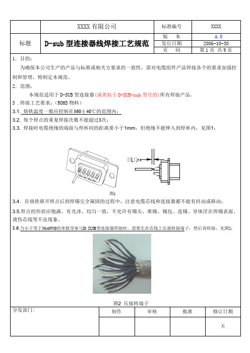
图2 压接转端子
制作审核
图3 包铜箔1
图5 焊接铜箔
方式二、先用双面导电的铜箔将后翻的编织屏蔽层导体缠绕至少一周,然后将铜箔间的接缝处用焊锡焊。
在内模包完铜箔后,将铜箔与连接器的铁壳360°均匀焊接,然后将包在内模上的铜箔和包在编织屏蔽层导体上的铜箔之间的接缝用焊锡360°均匀焊接,见图
图6 在编织上先包铜箔
图7 焊接铜箔
)、建议包铜箔前要先在内模上包一层隔热胶纸来防止芯线在焊铜箔或注塑外模时被烫伤;)、包覆的铜箔不允许有开缝或破损;
)、完全包完铜箔后,从任何角度观察都不允许看到有内模或芯线外露;
)、不允许出现焊锡溶入内模与连接器的缝隙以及焊锡渗入内模的隔热胶纸的现象。
>90°
°
9
图11 导线紧贴焊杯后壁
.如果焊接需要吹缩热缩管,套管应该完全套装焊接端子,且套装在电缆芯线上的长度应该为芯线
)焊点不湿润,或湿润角应大于90度,参见图9的第三张图面;
)无焊料或锡量不足,锡量不足指焊锡在焊杯中填充度小于75%为不合格;参见图
线材
图13焊杯上残留锡尖
)对于连接器中存在有单板的焊接,要求焊锡爬在导体上的高度小于导体直径的
)焊点存在扰动现象,即焊锡未充分融化下发生的操作动作造成的,例如明显的锡拉尖、锡包(锡过多)或者桥接等现象,不符合焊点间距的最小电气间隙的要求,可参见图14
图14 锡包
图15 焊接导体裸露过长
)导线的焊接未贴紧连接器焊杯后壁进行焊接,且电缆芯线歪斜影响后续相关操作为不合格,参见图
图16 导线焊接歪斜影晌后续操作。

关键字:接插件耳机插座 USB DC电源输入插座串口母口这篇文章集合了包括:耳机插座,DC电源输入插座,USB B型母头,DB9 串口母口插座,SD卡插座的尺寸和管脚资料。
是一篇实用性很强的技术文。
以下是正文部分:工程师画PCB的时候,难免会遇到一些连接器件,在中国,由于一些原因,很多时候,这些连接器件很难像国外那样,能向厂家索要机械尺寸文档,所以很多时候,都需要手拿游标卡尺去量。
这样就造成,一来我们不知道连接器的管脚接线,很容易连接错误;二来自己测量的,总有误差,最后画出来的PCB接插件按不上去。
接插件的标准化与否和尺寸标准图是否完全,我看这就是中国与国外的差距之一。
不单在芯片方面,而是在这些细节方面我们做得也不好。
耳机插座尺寸这是我们在电子市场上买到的3.5mm立体声耳机插座。
它的机械尺寸如下:从耳机插座底面的管脚旁边会有①②③④⑤的编号,对应尺寸图。
一般来说耳机采用3段式的插头,插头直径一般有3.5mm和2.5mm,不同直径的插头对应不同直径孔的耳机插座,所以“公”和“母”要对应.根据三段式的耳机插头的接线,就可以确定耳机插座的连接:1 脚接地,2脚接右声道(Right),5脚接左声道(Left)。
在耳机接头没插入插座的时候,2脚和3脚,4脚和5脚是接在一起的,而一旦接头插入插座的时候,2脚和3脚,4脚和5脚会分开。
所以从系统可靠性的角度来说,3脚和4脚应该接地,这样的话,耳机没插的时候,左右声道输入接地,系统输入为0。
很多时候,我们都会把不用的3脚4脚悬空,那么2脚和5脚也是悬空的,这样带来的风险就是,万一会从外界串入一个大电流,会从2脚和5脚传到板子上,从而会烧毁芯片。
本耳机插座的尺寸图:/Upload/2010/4/7/cd62f3f2-81e3-4a3e-b394-dc4 583c8af26.rar耳机接头除了有三段式之外,还有四段式,四段式比三段式加多了一个话筒/接听键,国标(大部分手机)从头到尾(尾巴是有线那边)的定义是:左声道、右声道、MIC、地。

32路通用继电器隔离数字输出模块(端子板控制柜装配的革命性变化,使接线变得异常简单1、简介XS-32DO 32路多功能通用继电器隔离数字输出模块(端子板,主要是配合DCS 数字量输出卡或PLC 数字输出模块使用。
可用来控制现场的电动机、电动门、电磁阀等装置。
可配西门子PLC 322-1BL00\1BH02等模块。
2、技术指标通道数 32 信号类型开关量输出隔离型式继电器隔离触点操作次数大于10万次最大触点操作频率 1800次/小时触点供电类型 AC220V\DC24V 可选特殊要求需定制阻性负载 24VDV 5A , 240VAC 5A 触点容量感性负载 24VDV 2A , 240VAC 2A线包供电 24V DC线包接法共阴\共阳任意设置外部供电电源 AC220V/DC24V 回路保险便捷拔插式LED 指示电源:红色\回路:绿色\保险熔断:红色内部接口形式 D-SUB 25P 母头冗余配置外部接线形式整体可拔插螺钉端子M3.5 PLC 模块供电DC24V 3A 功耗每点约0.6W 工作温度 0℃~60℃安装形式支架螺钉安装安装孔465*101 外形尺寸482*152mm3、使用说明n 主要功能信号隔离和驱动、回路供电、模块供电;输入型式:线圈侧共阴共阳选择,可适用各种DCS 、PLC 及控制仪表接入模式; 输出型式:可拼接为AC220V 或DC24V 有源输出、无源常开接点、无源常闭接点输出; 指示:绿色LED 指示动作情况、红色LED 作为保险熔断报警指示;保护:电源回路采取了过压、过流、反接保护措施;各回路均配备方便拔插的保险,兼具电源开关功能;接线:输入侧为标准D-SUB 25P 母头接插件,冗余配置(DB1-1和DB1-2冗余,DB2-1和DB2-2冗余;输出侧为拔插式螺钉端子。
n 接线端子说明输入侧输出接线输入侧输出接线回路号 DB1 TM1回路号 DB2 TM2 1 2 1A 1B 17 2 17A 17B 2 3 2A 2B 18 3 18A 18B 3 4 3A 3B 19 4 19A 19B 4 5 4A 4B 20 5 20A 20B 5 6 5A 5B 21 6 21A 21B 6 7 6A 6B 22 7 22A 22B 787A 7B23823A23B8 9 8A 8B 24 9 24A 24B9 12 9A 9B 25 12 25A 25B10 13 10A 10B 26 13 26A 26B11 14 11A 11B 27 14 27A 27B12 15 12A 12B 28 15 28A 28B13 16 13A 13B 29 16 29A 29B14 17 14A 14B 30 17 30A 30B15 18 15A 15B 31 18 31A 31B16 19 16A 16B 32 19 32A 32B内供电+ 1/11 24V+ 内供电+ 1/11 24V+内供电- 10/20 0V 内供电- 10/20 0V外部供电L(+ N(- 外部供电L(+ N(- n跳线说明输出型式从下列任选其一:无源常开输出(有保险、无源常开输出(无保险、无源常闭输出、DC24V有源共阴输出(有保险、AC220V有源共阴输出(有保险、DC24V有源共阴输出(无保险、AC220V有源共阴输出(无保险。
T ABLE O F C ONTENTSPage 1Description PageIC Socket/PGA Socket/PLCC/Screw Machine Pin 2~16IC Socket Technology Information22.54mm IC Sockets / IC Socket Adapter 31.778mm IC Socket / IC Socket Adapter 42.54mm PIN Connectors52.54mm SIP Socket (Mating Pin 0.76mm) 62.54mm SIP Socket (Mating Pin 0.47mm)72.54mm SIP Socket & PIN Connectors (Ultra Low)82.00mm SIP Socket / PIN Connectors 91.778mm SIP Socket / PIN Connectors 101.27mm SIP Socket 111.27mm Pin Connectors122.54mm Pin Grid Arrays & Adapter 13Chip Carrier Sockets for PLCC14Screw Machine Pin - Printed Circuit Pins 15Screw Machine Pin - Pin Receptacles 16PIN Header17~261.00mm Pin Header171.27mm Pin Header Straight DIP 181.27mm Pin Header Right Angle Type 191.27mm Pin Header S.M.T Type 202.00mm Pin Header Straight DIP 212.00mm Pin Header Right Angle Type 222.00mm Pin Header S.M.T Type 232.54mm Pin Header Straight DIP 242.54mm Pin Header Right Angle Type 252.54mm Pin Header S.M.T Type26Female Header27~381.00mm Female Header271.27mm Female Header S.M.T Type 281.27mm Female Header W/P S.M.T Type 291.27mm Female Header Straight DIP Type301.27 x 2.54mm Female Header Straight DIP Type 312.00mm Female Header S.M.T Type322.00mm Female Header Straight DIP Type 332.00mm Female Header Right Angle Type 342.00mm Female Header Bottom Entry Type352.54mm Female Header Straight / Right Angle Type 362.54mm Female Header DIP / S.M.T Type 372.54mm Female Header Bottom Entry Type 38Box Header / Ejector Header / I.D.C 39~441.27 x 1.27mm Box Header 391.27 x 2.54mm Box Header 402.00mm Box Header 412.00mm Ejector Header42Description Page2.54mm Box Header / Ejector Header 43I.D.C Socket:1.27 / 2.00 / 2.54mm 44DIN 41612 Eurocard Connector 45~48DIN 41612 Eurocard Connector 3-96 Pin 45DIN 41612 Eurocard Connector 3-48 Pin 46DIN 41612 Eurocard Connector 2-64 Pin 47DIN 41612 Eurocard Connector 2-32 Pin 48Board Mount Telephone Modular Jacks 49~55 49 50 51 52S 53 54 55USB / Mini USB Connector 56~57USB Type-A Receptacle Connector 56Mini USB Receptacle Connector 57HDMI Connector 58~59HDMI Connector (With Flange) 58HDMI Connector (Without Flange) 59D subminiature Connector 60~66High Density Right Angle DIP Solder D-Sub 60High Density Cup Solder D-Sub 61High Density DIP Solder D-Sub 628.10mm Footprint Right Angle DIP Solder D-Sub 63Straight Cup Solder D-Sub 64Straight DIP Solder D-Sub 65DVI Right A ngle Digital Connector 66FFC / FPC Connector 67~690.5mm SMT ZIF FFC/FPC Downside Type Conn. 670.5mm SMT ZIF FFC/FPC Vertical Type Conn. 681.0mm DIP LIF FFC/FPC Top Entry Connector 69Wire to Board Connector 70~761.25mm Wire to Board Connector 702.00mm Wire to Board Connector 712.00mm Wire to Board Connector 722.50mm Wire to Board Connector 732.54mm Wire to Board Connector 743.96mm Wire to Board Connector 753.96mm Wire to Board Connector 76Optional Panel Ground Out Shield, Contacts: 8,10 Right Angle / Straight, Shield, Contacts: 8,10Right Angle /Straight, Contacts: 4, 6, 8Right Angle, Contacts: 4, 6, 8traight, Contacts: 4, 6, 8Right Angle, Contacts: 4, 6Right Angle, Ports: 1, 2, 4, 6, 8IC socket / PCB Connectors/ PGA Socket / PLCC SocketPitch:2.54mm / 2.00m / 1.778mm /1.27mm / 1.00mmDue to technical progress, all the information provided is subject to change without prior notice. Page 2IC SocketPitch:2.54mmIC Solder AdapterSolder Type, SMT Type, Wire-WrapTechnical Specs:Insulator: Black glass filled polyester PBT-GF30-FR Flammability: UL 94V-OPIN(Sleeve): Brass CuZn36Pb3 (C36000)Contact clip (4 finger): Beryllium copper (C17200)Accepted pin : 0.40 to 0.56 mmForces(IC Socket): (polished steel gauge 0.43 mm) -- Insertion 2 N typ. -- Withdrawal 1 N typ.Mechanical life: min 500 cycles Rated current: 1 AContact resistance: max 10 mDielectric strength: min 1000 V RMS5263.5022.8666.0425.4081.286478.7422.8625.402833.0215.2435.5640.6445.7250.8053.3460.9663.5066.0463.50525048503640423258.4260.9663.5060.9615.2422.8615.2415.2438.1043.1848.2650.8015.2415.2415.2415.2440.6430.48322438.1027.9410.1615.2417.7817.7825.4017.7817.7817.7817.7817.7817.7812.7017.78Dim A Contact Dim B Dim CDim D IC SocketWire - WrapPage 3Due to technical progress, all the information provided is subject to change without prior notice.Technical Specs:Insulator: Black glass filled polyester PBT-GF30-FR Flammability: UL 94V-OPIN (Sleeve): Brass CuZn36Pb3 (C36000)Rated current: 1 AContact resistance: max 10 m1000 V RMSAccepted pin :0.40 to 0.56 mmForces: (polished steel gauge 0.43 mm)-- Insertion 2 N typ.-- Withdrawal 1 N typ.Mechanical life: min 100 cyclesIC Socket:Poles A B C16 14.6 7.62 10.128 25.2 10.16 12.730 27.0 10.16 12.732 28.8 10.16 12.748 43.1 10.16 12.720 18.1 15.24 17.6424 21.7 15.24 17.6428 25.2 15.24 17.6440 35.8 15.24 17.6442 37.7 15.24 17.6448 43.1 15.24 17.6452 46.7 15.24 17.6456 50.2 15.24 17.6464 57.3 15.24 17.6468 60.9 15.24 17.6464* 57.3 19.05 21.5 IC Socket Adapter:IC Socket - Solder Type Pitch:1.778mmIC Socket Adapter - Solder Type Pitch:1.778mmPage 4Due to technical progress, all the information provided is subject to change without prior notice.Flammability: UL 94V-OContact: Brass CuZn36Pb3 (C36000)Connecting pins : 0.47 mmMechanical life: min 500 cycles Rated current: 3 ADielectric strength: min1000 V RMSPage 5Due to technical progress, all the information provided is subject to change without prior notice.Flammability: UL 94V-OSleeve: Brass CuZn36Pb3 (C36000)Contact clip (6 finger): Beryllium copper (C17200)Mating pins:0.70 to 0.90 mm, 0.635 mm Forces: (polished steel gauge 0.76 mm)-- Insertion 2 N typ.-- Withdrawal 1 N typ.Mechanical life: min 500 cycles Rated current: 3 AContact resistance: max 10 mDielectric strength: min 1000 V RMSCoplanarity SMD max 0.1 mm (measured on terminations: 25 mmlong connectors)Page 6Due to technical progress, all the information provided is subject to change without prior notice.2Number of Contacts:Single row = 01 to 40Double row=02 to 803Dip Spacing:0=Single row 1=Double rowOrdering Code2XX 3X 4X 576X 7XX11411Series No.:141=SIP Socket6Plated(Sleeve / Contact):0 = Tin 200u" / Tin 200u"1 = Tin 200u" / Gold Flash 2 = Tin 200u" / Gold 5u"3 = Tin 200u" / Gold 15u"4 = Tin 200u" / Gold 30u"5 = Gold Flash / Gold Flash 5Insulator Height 7=7.00mm4Tail & Mounting Style:S=Straight DIP Type M=Straight S.M.T Type R =Right A ngle Type 7Pin TypeSee Page 15~16Flammability: UL 94V-OSleeve: Brass CuZn36Pb3 (C36000)Contact clip (6 finger): Beryllium copper (C17200)Mating pins:0.40 to 0.56 mmForces: (polished steel gauge 0.43 mm)-- Insertion 2 N typ.-- Withdrawal 1 N typ.Mechanical life: min 500 cycles Rated current: 3 AContact resistance: max 10 mDielectric strength: min 1000 V RMSCoplanarity SMD max 0.1 mm (measured on terminations: 25 mmlong connectors)Page 7Due to technical progress, all the information provided is subject to change without prior notice.2Number of Contacts:Single row = 01 to 40Double row=02 to 803Dip Spacing:0=Single row 1=Double rowOrdering Code2XX 3X 4X 5X 6X 7XX11411Series No.:141=SIP Socket6Plated(Sleeve / Contact):0 = Tin 200u" / Tin 200u"1 = Tin 200u" / Gold Flash 2 = Tin 200u" / Gold 5u"3 = Tin 200u" / Gold 15u"4 = Tin 200u" / Gold 30u"5 = Gold Flash / Gold Flash 5Insulator Height 3=3.00mm4Tail & Mounting Style:S=Straight DIP Type M=Straight S.M.T T ype R =Right A ngle Type 7Pin TypeSee Page 15~16Flammability: UL 94V-OSleeve: Brass CuZn36Pb3 (C36000)Contact clip (6 finger): Beryllium copper (C17200)Mating pins:0.40 to 0.56 mmForces: (polished steel gauge 0.43 mm)-- Insertion 2 N typ.-- Withdrawal 1 N typ.Mechanical life: min 500 cycles Rated current: 3 AContact resistance: max 10 mDielectric strength: min1000 V RMSPage 8Due to technical progress, all the information provided is subject to change without prior notice.2Number of Contacts:Single row = 01 to 40Double row=02 to 803Dip Spacing:0=Single row 1=Double rowOrdering Code2XX 3X 4X 5X 6X 7XX11411Series No.:141=SIP Socket6Plated(Sleeve / Contact):0 = Tin 200u" / Tin 200u"1 = Tin 200u" / Gold Flash 2 = Tin 200u" / Gold 5u"3 = Tin 200u" / Gold 15u"4 = Tin 200u" / Gold 30u"5 = Gold Flash / Gold Flash 5Insulator Height 1=1.30mm 2=1.90mm4Tail & Mounting Style:S=Straight DIP Type M=Straight S.M.T Type R =Right A ngle Type 7Pin TypeSee Page 15~16Flammability: UL 94V-OSleeve: Brass CuZn36Pb3 (C36000)Contact clip (6 finger): Beryllium copper (C17200)Mating pins:0.40 to 0.56 mmForces(SIP Socket): (polished steel gauge 0.43 mm) -- Insertion 2 N typ. -- Withdrawal 1 N typ.Mechanical life: min 500 cycles Rated current: 3 AContact resistance: max 10 mDielectric strength: min1000 V RMSPage 9Due to technical progress, all the information provided is subject to changewithout prior notice.Flammability: UL 94V-OSleeve: Brass CuZn36Pb3 (C36000)Contact clip (6 finger): Beryllium copper (C17200)Mating pins:0.40 to 0.56 mmForces(SIP Socket): (polished steel gauge 0.43 mm) -- Insertion 2 N typ. -- Withdrawal 1 N typ.Mechanical life: min 500 cycles Rated current: 3 AContact resistance: max 10 mDielectric strength: min1000 V RMSPage 10Due to technical progress, all the information provided is subject to change without prior notice.2Number of Contacts:Single row = 01 to 40Double row=02 to 803Dip Spacing:0=Single row 1=Double rowOrdering Code2XX 3X 4X 536X 7XX11X71Series No.:147=SIP Socket Pitch:1.778mm137=PIN Connectors Pitch:1.778mm6Plated(Sleeve / Contact):0 = Tin 200u" / Tin 200u"1 = Tin 200u" / Gold Flash 2 = Tin 200u" / Gold 5u"3 = Tin 200u" / Gold 15u"4 = Tin 200u" / Gold 30u"5 = Gold Flash / Gold Flash 6 = Gold 3u" / Gold 3u"7 = Gold 5u" / Gold 5u"8 = Gold 10u" / Gold 10u"5Insulator Height 3=3.00mm 4Tail & Mounting Style:S=Straight DIP Type M=Straight S.M.T Type R =Right A ngle Type 7Pin TypeSee Page 15~16Flammability: UL 94V-OSleeve: Brass CuZn36Pb3 (C36000)Contact clip (6 finger): Beryllium copper (C17200)Mating pins:0.38 to 0.50 mmForces: (polished steel gauge 0.41 mm) -- Insertion 0.5 N typ. -- Withdrawal 0.2 N typ.Mechanical life: min 500 cycles Rated current: 1 AContact resistance: max 20 m Dielectric strength: min 500 V RMSCoplanarity SMD max 0.1 mm (measured on terminations: 25 mmlong connectors)Page 11Due to technical progress, all the information provided is subject to change without prior notice.Flammability: UL 94V-OContact: Brass CuZn36Pb3 (C36000)Contact pin:•0.41mm Mechanical life: min 500 cycles Rated current: 1 ADielectric strength: min 1000 V RMS Coplanarity SMDterminations: max 0.1 mm (measured on 25 mm longconnectors)Page 12Due to technical progress, all the information provided is subject to change without prior notice.2Number of Contacts:Single row = 01 to 40Double row=02 to 803Dip Spacing:0=Single row 1=Double rowOrdering Code2XX 3X 4X 546X 7XX11331Series No.:133=PIN Connectors Pitch:1.27mm5Insulator Height 2=2.20mm 2=1.90mm 4Tail & Mounting Style:S=Straight DIP Type M=Straight S.M.T T ype R =Right A ngle Type 7Pin TypeSee Page 15~166PIN Plated:0 = Tin 200u" / Tin 200u"5 = Gold Flash / Gold Flash 6 = Gold 3u" / Gold 3u"7 = Gold 5u" / Gold 5u"8 = Gold 10u" / Gold 10u"Pin grid array Socket & AdapterPitch:2.54mmSolder TypeTechnical Specs:Insulator: Black glass filled polyester PBT-GF30-FRFlammability: UL 94V-OSleeve: Brass CuZn36Pb3 (C36000)Contact clip (4 finger): Beryllium copper (C17200)Accepted pin: 0.40 to 0.56 mmForces: (polished steel gauge 0.46 mm)-- Insertion 0.7 N typ.-- Withdrawal 0.4 N typ.Mechanical life: min 100 cyclesRated current: 1 AContact resistance: max 10 mDielectric strength: min 1000 V RMSCalculate with n1 = number of contacts in one line andn2 = characteristic size of the windowA = n1x2.54B = (n1-1)x2.54C = (n2x2.54)-0.40PGA basic body 11X11Number of contacts: 68PGA basic body 13X13Number of contacts: 84PGA basic body 13X13Number of contacts: 121PGA basic body 14X14Number of contacts: 132PGA basic body 17X17Number of contacts: 241PGA basic body 17X17Number of contacts: 169PGA basic body 16X16Number of contacts: 156PGA basic body 15X15Number of contacts: 145PGA basic body 20X20Number of contacts: 400PGA basic body 19X19Number of contacts: 306PGA basic body 19X19Number of contacts: 238PGA basic body 18X18Number of contacts: 225Ordering Code2XXX3X4X5XX6X115X2Number of Contacts:068=68 Pin306=306 Pin......1Series No.:152=Pitch 2.54mm PGA Socket151=Pitch 2.54mm PGA Socket Adapter3PGA basic body sizel:...... 7=7X78=8X8 9=9X90=10X10 A=11X11B=12X12 C=13X13D=14X14 E=15X15......4Insulator Material:1 =2 = PPSFR-4Page 13 Due to technical progress, all the information provided is subject to change without prior notice.6Plated(Sleeve / Contact):0 = Tin 200u" / Tin 200u"1 = Tin 200u" / Gold Flash2 = Tin 200u" / Gold 5u"3 = Tin 200u" / Gold 15u"4 = Tin 200u" / Gold 30u"5 = Gold Flash / Gold Flash6 = Gold 3u" / Gold 3u"7 = Gold 5u" / Gold 5u"8 = Gold 10u" / Gold 10u"7Pin TypeSee Page 15~16PLCC SocketSockets for Plastic Leaded Chip CarriersSMT Terminations / Sollder TypeTechnical Specs:Insulator: Black glass filled polyester PPS-GF30-FRFlammability: UL 94V-OContact: Phosphor bronzeContact pressure: min 1.5 N per contactMechanical life: min 50 cyclesRated current: 1 AContact resistance: max 20 mDielectric strength: min 600 V RMSInsulation resistance: min 5000 MCapacitance: max 2 pFCoplanarity SMDterminations: max 0.1 mmOrdering Code2XX3X45X6X7811296Height over PC Board0=3.80mm1=4.15mm2=4.60mm78Customer Request2Number of Contacts:20,28,32,44,52,68,841Series No.:129=PLCC Chip Carrier Socket5 Packing method:0 = Tube1 = T ape Reel3Tail& Mounting Style:S = Straight DIP TypeM = Straight S.M.T T ype4Body Color:1=BrownPage 14Due to technicalprogress, all the information provided is subject to change without prior notice.SCREW MACHINE PINS----Printed Circuit PinsDue to technical progress, all the information provided is subject to change without prior notice.Page 15SCREW MACHINE PINS----Pin ReceptaclesDue to technical progress, all the information provided is subject to change without prior notice. Page 16SPECIFICATIONS:Current Rating: 1.0 AMPContact Resistance: 30m Max Insulation Resistance: 500M Min Withstand V oltage: 500V AC/minute Operation T emperature: -40 to +105Max Process T emp: 230 for 30~60 secretary.MATERIALS:Contact Material: BrassContact Plating: Gold or Tin over 50Ni Insulator Material: Polyester(UL94V-0) Standard: LCPOrdering CodeSeries No.:3= Pin Header10XXX 918X 7X 6X 5XX 4X 3X 25131Pitch: 5= 1.00mm2Dip Spacing:1=Single row 2=Double row 4Number of Contacts:Single row = 01 to 50Double row=02 to 98 x0=100pin 5Insulator Height: 1 = 1.00mm 5 = 1.50mm3Contact Plated0=Tin 1=Gold Flash 2=Gold 3u" 3=Gold 5u"4=Gold 10u" 5=Gold 15u"6= Gold 30u"7Tail & Mounting Style:S=Straight DIP type M=Straight SMT type6Material Type0=PPS 3=Nylon-66 1=PBT 4=Nylon-6T 2=LCP 5=P A468Tiers of Body 1 = Single tier 2 = Double tier 3 = T riple tier9Pin LengthXXX=A+H+C10Page 17Due to technicalprogress, all the information provided is subject to change without prior notice.SPECIFICATIONS:Current Rating: 1.0 AMPContact Resistance: 30m Max Insulation Resistance: 1000M Min Withstand Voltage: 300VAC/minute Operation Temperature: -40 to +105MATERIALS:Contact Material: BrassContact Plating: Gold or Tin over 50Ni Insulator Material: Polyester(UL94V-0) Standard: PA 46••Ordering CodeSeries No.:3= Pin Header10XXX 9X 857X 6S 5XX 4X 3X 23131Pitch: 3= 1.27mm2Dip Spacing:1=Single row 2=Double row 4Number of Contacts:Single row = 01 to 50Double row=02 to 98 x0=100Pin 5Insulator Height:1 = 1.00mm2 = 2.00mm3 = 2.50mm 5 = 1.50mm 6 = 1.60mm 7 = 1.70mm 8 = 0.80mm 9 = 0.65mm3Contact Plated 0=Tin1=Gold Flash 2=Gold 3u" 3=Gold 5u"4=Gold 10u"5=Gold 15u"6= Gold 30u"7Tail & Mounting Style:S=Straight DIP type6Material Type 2=LCP 3=Nylon-664=Nylon-6T 5=PA468Tiers of Body 1 = Single tier 2 = Double tier 3 = T riple tier9Pin LengthXXX=A+B+C10Page 18Due to technical progress, all the information provided is subject to changewithout prior notice.SPECIFICATIONS:Current Rating: 1.0 AMPContact Resistance: 30m Max Insulation Resistance: 1000M Min Withstand Voltage: 300VAC/minute Operation T emperature: -40 to +105MATERIALS:Contact Material: BrassContact Plating: Gold or Tin over 50Ni Insulator Material: Polyester(UL94V-0) Standard: PA 46••Ordering CodeSeries No.:3= Pin Header10XXX 91857X 6R 5XX 4X 3X 23131Pitch: 3= 1.27mm2Dip Spacing:1=Single row 2=Double row 4Number of Contacts:Single row = 01 to 50Double row=02 to 98 x0=100Pin 5Insulator Height:1 = 1.00mm2 = 2.00mm3 = 2.50mm 5 = 1.50mm 6 = 1.60mm 7 = 1.70mm 8 = 0.80mm 9 = 0.65mm3Contact Plated 0=Tin1=Gold Flash 2=Gold 3u" 3=Gold 5u"4=Gold 10u"5=Gold 15u"6= Gold 30u"7Tail & Mounting Style:R=Right Angle DIP T ype6Material Type 2=LCP 3=Nylon-664=Nylon-6T 5=PA468Tiers of Body 1 = Single tier 2 = Double tier 3 = T riple tier9Pin LengthXXX=A+H+C10Page 19Due to technical progress, all the information provided is subject to changewithout prior notice.SPECIFICATIONS:Current Rating: 1.0 AMPContact Resistance: 30m Max Insulation Resistance: 1000M Min Withstand Voltage: 300VAC/minute Operation Temperature: -40 to +105MATERIALS:Contact Material: BrassContact Plating: Gold or Tin over 50Ni Insulator Material: Polyester(UL94V-0) Standard: PA 46••Ordering CodeSeries No.:3= Pin Header10XXX 9X 8X 7X 6M 5XX 4X 3X 23131Pitch: 3= 1.27mm2Dip Spacing:1=Single row 2=Double row 4Number of Contacts:Single row = 01 to 50Double row=02 to 98 x0=100Pin 5Insulator Height:1 = 1.00mm2 = 2.00mm3 = 2.50mm 5 = 1.50mm 6 = 1.60mm 7 = 1.70mm 8 = 0.80mm 9 = 0.65mm3Contact Plated 0=Tin1=Gold Flash 2=Gold 3u" 3=Gold 5u"4=Gold 10u"5=Gold 15u"6= Gold 30u"7Tail & Mounting Style:M=Straight SMT type6Material Type 2=LCP 3=Nylon-664=Nylon-6T 5=PA468Tiers of Body 1 = Single tier 2 = Double tier 3 = T riple tier9Pin LengthXXX=A+B+C10Page 20Due to technical progress, all the information provided is subject to changewithout prior notice.SPECIFICATIONS:Current Rating: 2.0 AMPContact Resistance: 30m Max Insulation Resistance: 1000M Min Withstand Voltage: 500VAC/minute Operation T emperature: -40 to +105MATERIALS:Contact Material: BrassContact Plating: Gold or Tin over 50Ni Insulator Material: Polyester(UL94V-0) Standard: PA46••Ordering CodeSeries No.:3= Pin Header10XXX 9X 8X 7X 6S 5XX 4X 3X 22131Pitch: 2= 2.00mm2Dip Spacing:1=Single row 2=Double row 4Number of Contacts:Single row = 01 to 40Double row=02 to 80 5Insulator Height: 2 = 2.00mm 5 = 1.50mm3Contact Plated0=Tin 1=Gold Flash 2=Gold 3u" 3=Gold 5u"4=Gold 10u" 5=Gold 15u"6= Gold 30u"7Tail & Mounting Style:S=Straight DIP type6Material Type0=PPS 3=Nylon-66 1=PBT 4=Nylon-6T 2=LCP 5=P A468Tiers of Body 1 = Single tier 2 = Double tier 3 = T riple tier9Pin LengthXXX=A+B+C10Page 21Due to technical progress, all the information provided is subject to changewithout prior notice.SPECIFICATIONS:Current Rating: 2.0 AMPContact Resistance: 30m Max Insulation Resistance: 1000M Min Withstand Voltage: 500VAC/minute Operation Temperature: -40 to +105MATERIALS:Contact Material: BrassContact Plating: Gold or Tin over 50Ni Insulator Material: Polyester(UL94V-0) Standard: PA46••Ordering CodeSeries No.:3= Pin Header10XXX 918X 7X 6R 5XX 4X 3X 22131Pitch: 2= 2.00mm2Dip Spacing:1=Single row 2=Double row 4Number of Contacts:Single row = 01 to 40Double row=02 to 80 5Insulator Height: 2 = 2.00mm 5 = 1.50mm3Contact Plated0=Tin 1=Gold Flash 2=Gold 3u" 3=Gold 5u"4=Gold 10u" 5=Gold 15u"6= Gold 30u"7Tail & Mounting Style:R=Right Angle DIP T ype6Material Type0=PPS 3=Nylon-66 1=PBT 4=Nylon-6T 2=LCP 5=P A468Tiers of Body 1 = Single tier 2 = Double tier 3 = T riple tier9Pin LengthXXX=A+H+C10Page 22Due to technical progress, all the information provided is subject to changewithout prior notice.SPECIFICATIONS:Current Rating: 2.0 AMPContact Resistance: 30m Max Insulation Resistance: 1000M Min Withstand Voltage: 500VAC/minute Operation T emperature: -40 to +105MATERIALS:Contact Material: BrassContact Plating: Gold or Tin over 50Ni Insulator Material: Polyester(UL94V-0) Standard: PA 46••Ordering CodeSeries No.:3= Pin Header10XXX 9X 8X 7X 6M 5XX 4X 3X 22131Pitch: 2= 2.00mm2Dip Spacing:1=Single row 2=Double row 4Number of Contacts:Single row = 01 to 40Double row=02 to 80 5Insulator Height: 2 = 2.00mm 5 = 1.50mm3Contact Plated0=Tin 1=Gold Flash 2=Gold 3u" 3=Gold 5u"4=Gold 10u" 5=Gold 15u"6= Gold 30u"7Tail & Mounting Style:M=Straight SMT type6Material Type0=PPS 3=Nylon-66 1=PBT 4=Nylon-6T 2=LCP 5=P A468Tiers of Body 1 = Single tier 2 = Double tier 3 = T riple tier9Pin LengthXXX=A+B+C10Page 23Due to technical progress, all the information provided is subject to changewithout prior notice.SPECIFICATIONS:Current Rating: 3.0 AMPContact Resistance: 30m Max Insulation Resistance: 1000M Min Withstand Voltage: 600VAC/minute Operation T emperature: -40 to +105MATERIALS:Contact Material: BrassContact Plating: Gold or Tin over 50Ni Insulator Material: Polyester(UL94V-0) Standard: PBT••Ordering CodeSeries No.:3= Pin Header10XXX 9X 8X 7X 6S 5XX 4X 3X 21131Pitch: 1= 2.54mm2Dip Spacing:1=Single row 2=Double row 4Number of Contacts:Single row = 01 to 40Double row=02 to 80 5Insulator Height: 3 = 2.50mm 5 = 1.50mm3Contact Plated0=Tin 1=Gold Flash 2=Gold 3u" 3=Gold 5u"4=Gold 10u" 5=Gold 15u"6= Gold 30u"7Tail & Mounting Style:S=Straight DIP Type6Material Type0=PPS 3=Nylon-66 1=PBT 4=Nylon-6T 2=LCP 5=P A468Tiers of Body 1 = Single tier 2 = Double tier 3 = T riple tier9Pin LengthXXX=A+B+C10Page 24Due to technical progress, all the information provided is subject to changewithout prior notice.SPECIFICATIONS:Current Rating: 3.0 AMPContact Resistance: 30m Max Insulation Resistance: 1000M Min Withstand Voltage: 600VAC/minute Operation T emperature: -40 to +105MATERIALS:Contact Material: BrassContact Plating: Gold or Tin over 50Ni Insulator Material: Polyester(UL94V-0) Standard: PBT••Ordering CodeSeries No.:3= Pin Header10XXX 918X 7X 6R 5XX 4X 3X 21131Pitch: 1= 2.54mm2Dip Spacing:1=Single row 2=Double row 4Number of Contacts:Single row = 01 to 40Double row=02 to 80 5Insulator Height: 3 = 2.50mm 5 = 1.50mm3Contact Plated0=Tin 1=Gold Flash 2=Gold 3u" 3=Gold 5u"4=Gold 10u" 5=Gold 15u"6= Gold 30u"7Tail & Mounting Style:R=Right Angle DIP T ype6Material Type0=PPS 3=Nylon-66 1=PBT 4=Nylon-6T 2=LCP 5=P A468Tiers of Body 1 = Single tier 2 = Double tier 3 = T riple tier9Pin LengthXXX=A+H+C10Page 25Due to technical progress, all the information provided is subject to change without prior notice.SPECIFICATIONS:Current Rating: 3.0 AMPContact Resistance: 30m Max Insulation Resistance: 1000M Min Withstand Voltage: 600VAC/minute Operation T emperature: -40 to +105MATERIALS:Contact Material: BrassContact Plating: Gold or Tin over 50Ni Insulator Material: Polyester(UL94V-0) Standard: PBT••Ordering CodeSeries No.:3= Pin Header10XXX 9X 857X 6M 5XX 4X 3X 21131Pitch: 1= 2.54mm2Dip Spacing:1=Single row 2=Double row 4Number of Contacts:Single row = 01 to 40Double row=02 to 80 5Insulator Height: 3 = 2.50mm 5 = 1.50mm3Contact Plated0=Tin 1=Gold Flash 2=Gold 3u" 3=Gold 5u"4=Gold 10u" 5=Gold 15u"6= Gold 30u"7Tail & Mounting Style:M=Straight SMT type6Material Type0=PPS 3=Nylon-66 1=PBT 4=Nylon-6T 2=LCP 5=P A468Tiers of Body 1 = Single tier 2 = Double tier 3 = T riple tier9Pin LengthXXX=A+H+C10Page 26Due to technical progress, all the information provided is subject to changewithout prior notice.SPECIFICATIONS:Current Rating: 1.0 AMPContact Resistance: 30m Max Insulation Resistance: 500M Min Withstand Voltage: 200VAC/minute Operation T emperature: -40 to +105Max Process Temp: 230 for 30~60 secretary.MATERIALS:Contact Material: Phosphor Bronze Contact Plating: Gold or Tin over 50Ni Insulator Material: Polyester(UL94V-0) Standard: LCP••Ordering CodeSeries No.:2= Female Header100918X 7X 6M 5XX 423225121Pitch: 5= 1.00mm2Dip Spacing:1=Single row 2=Double row 4Number of Contacts:Single row = 01 to 50Double row=02 to 98 x0=100 Pin 5Insulator Height: 2 = 2.0mm3Contact Plated 0=Tin1=Gold Flash 2=Gold 3u"3=Gold 5u"4=Gold 10u"5=Gold 15u"6= Gold 30u"7Tail & Mounting Style:M=Straight SMT type6Material Type 0=PPS 1=PBT 2=LCP 3=Nylon-664=Nylon-6T 5=PA468Color:1=Black9Customer Request10Page 27Due to technicalprogress, all the information provided is subject to change without prior notice.SPECIFICATIONS:Current Rating: 1.0 AMPContact Resistance: 30m Max Insulation Resistance: 1000M Min Withstand Voltage: 300VAC/minute Operation Temperature: -40 to +105MATERIALS:Contact Material: Phosphor Bronze Contact Plating: Gold or Tin over 50Ni Insulator Material: Polyester(UL94V-0) Standard: PA 46••Ordering CodeSeries No.:2= Female Header100918X 7X 6M 5XX 4X 3X 23121Pitch: 3= 1.27mm2Dip Spacing:1=Single row 2=Double row 4Number of Contacts:Single row = 01 to 50Double row=02 to 98 x0=100 Pin 5Insulator Height: 2 = 2.0mm 3 = 3.4mm 4 = 4.3mm 5 = 4.6mm3Contact Plated 0=Tin1=Gold Flash 2=Gold 3u"3=Gold 5u"4=Gold 10u"5=Gold 15u"6= Gold 30u"7Tail & Mounting Style:M=Straight SMT type6Material Type 0=PPS 1=PBT 2=LCP 3=Nylon-664=Nylon-6T 5=PA468Color:1=Black9Customer Request10H = 2.0mm H = 3.4mm H = 4.3mmH = 4.4mmPage 28Due to technical progress, all the information provided is subject to changewithout prior notice.。
大型电子表决系统技术资料系统概述CU8000是一套集快速、安全、稳定为一身的电子表决系统,通过该系统,与会代表只需根据会议议程轻按表决器按钮,即可轻松实现签到和各类议案的电子表决工作。
系统支持第一次按键有效或最后一次按键有效、记名或不记名模式。
系统居于网络化控制模式,极大提升了系统速度。
从1个甚至几千个席位的表决系统,都能够在0.5秒-1.2秒内完成表决并精确地统计出表决结果。
系统具有远距离驱动能力,每条干线距主机100米外至少能驱动60个表决器,因此系统完全能够满足任何大会场机房至场内后排距离较远的要求。
整个系统在长时间不间断开机运行仍然可确保其稳定、安全及准确性,为各大中小型会议场合之首选。
本系统的可靠性、安全性居于国际领先水平。
产品符合符合IEC914、RoHS及CE等国际标准。
适用于任何大中小型会议场所。
系统技术特点1、支持多主机直接级联,自动识别ID,无需任何设定表决控制器与扩展控制设备可以通过RJ45直接级联,电脑一个Rs232串口可以接驳10台主机,制器与扩展控制设备手拉手连接即可,而无需通过网络交换机,易于系统容量扩展。
实现表决数据无延时,高速传递,加快系统速度、提高系统稳定性。
表决控制器与扩展控制设备连接,即可自动识别ID,无需任何设定,可以彼此互为替换使用。
2、系统容量一路Rs232同时接驳10部表决控制器或扩展控制设备,可以支持1800个表决器同时表决;一台电脑多个Rs232同时工作,可接驳多路表决控制器或扩展控制设备同时工作。
即系统容量可以无限大。
3、支持表决器的串接、并接或者串并混接表决器支持串接、并接或者串联与并联混接。
在一个会场里,可根据实际情况选择适合的布线,施工更具灵活性。
4、双存储器支持存储所有表决结果表决单元双存储器可存储所有表决结果,在重起电脑后仍可以读取表决数据,彻底解决因停电/系统瘫痪等原因后无法统计结果的弊端,对会后数据的保存备份尤为重要。
体现系统可靠性和安全性。